Page is loading ...

1
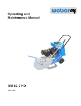
Operating and
Maintenance Manual
SM 57-2
0401303

2

3
Table of contents
Introduction 4
Safety guidelines 5
Graphic presentation 8
Device description 9
Technical data 10
Activities prior to starting work 12
Starting 13
Cutting 14
Taking out of operation 15
Maintenance overview 16
Maintenance work 17
Operating uids and ll levels 19
Troubleshooting 19
Storage 20

4
Introduction
This operating and maintenance manual is designed to facilitate familiarization with your joint
cutter, and enable you to maintain it and use it for its proper purpose.
When complying with the instructions in the operating and maintenance manual you help to
avoid hazards, reduce repair and downtime costs, and increase the reliability and service life of
your joint cutter.
This operating and maintenance manual must always be available where the joint cutter is used.
If necessary you can obtain additional information from your authorized WEBER dealer, or you
can obtain information from one of the contact addresses on the last page.
The valid conformity declaration is enclosed with every machine delivery.
You can obtain information on the assembled Honda petrol engine and nd a spare-part list for it at
www.honda-engines-eu.com.

5
Safety guidelines
General
All safety instructions must be read and complied with, non-compliance results in
- Danger to life and limb of the user
- Impairments to the machine or other property.
In addition to the operating manual, the accident-prevention regulations in the country where the
appliance is used must be complied with.
Intended use
The joint cutter should only be used if it is in a technically faultless condition, for its proper purpose,
in a safety-conscious and hazard-conscious manner, and in compliance with the instructions in the
operating manual. Malfunctions that impair safety must be eliminated without delay.
The joint cutter type SM 57-2 is only intended for cutting:
- bituminous material (road surfaces); and
- concrete
Any other use of the joint cutter is considered to be improper use for which the owner shall be
exclusively responsible. All liability is rejected if damage occurs due to non-compliance with this
provision. This risk is borne solely by the user.
Operation
Joint cutters must only be operated by suitable personnel of at least 18 years of age. Operators
must be instructed by the owner or by the owner’s personnel in how to guide the joint cutter.
The machine operator must comply with trac regulations. If instructions that aect safety are given
by third persons, then the operator must be authorized to reject these instructions.
Protective equipment
Easily foreseeable misuse
Any use for which the machine is not intended.
Unauthorized persons are forbidden from being in the area of the joint cutter during the cutting
process.
Protective equipment includes:
Hearing protection
Hard hat
Safety shoes
This machine is capable of exceeding the permissible sound level of 80 dB(A). The owner might also
face additional dangers when using the machine. Precautionary action must, therefore, be taken.
Protective gloves

6
Maintenance and repair work
Only use original Weber spare parts for maintenance or repair work to ensure reliable and safe
operation.
For repair, maintenance, or inspection work the engine of the joint cutter must be prevented from
being started unintentionally.
All pressurized lines, particularly hydraulic lines and lines of the injection system of the drive motor
must be depressurized before performing maintenance or repair tasks.
For maintenance and repair tasks the joint cutter must be placed on a level and stable surface and
must be secured from rolling o or tipping over.
Heavy components and assemblies must be secured to and lifted by hoisting machines that can
bear their weight when they are replaced. Ensure that no hazard is caused by raising components or
assemblies.
Do not position yourself or work under suspended loads.
Operation under dicult conditions
Never inhale the exhaust gas; it contains carbon monoxide, a colorless and odorless gas that
is extremely hazardous, which, if inhaled even briey, can cause unconsciousness and death.
Therefore, never operate the engines in enclosed areas or in areas that are poorly ventilated
(tunnels, caves, etc.). Exercise particular caution when operating the engine in the vicinity of
people and livestock.
Hydraulic hose lines must be checked at regular intervals in accordance with standard engineering
practice, or they must be replaced at appropriate intervals, even if no signs of safety-relevant defects
are present.
Adjusting tasks, maintenance tasks, and inspection tasks must be carried out on schedule as
specied in this operating and maintenance manual. These activities should only be executed by
trained personnel.
Operation
Prior to starting work the owner of the joint cutter must be familiar with the working environment.
The working environment includes obstacles in the work and trac area, the bearing capacity of the
ground, as well as the necessary safeguarding of the construction site in the area adjacent to public
trac; and it also includes compliance with trac regulations.
The joint cutter should only be operated when all the protective xtures are mounted. The protective
xtures must all be in functional condition.
At least once per shift the joint cutter must be checked for defects that can be detected from the
outside. If defects are found then operation of the joint cutter must be stopped immediately and the
responsible person must be informed. Prior to restarting, joint cutter malfunctions that have occurred
must be corrected.
If lubricating oils and fuel come into contact with skin, they can cause skin cancer. Upon contact
with the skin, clean aected skin with suitable cleaning agent without delay.

7
Inspection
Joint cutters must be inspected in accordance with the corresponding conditions of use and operation
as needed; however, an inspection to ensure they are operationally safe must be performed by an
expert at least once a year. The results of the inspection must be recorded in writing and must be
stored at least until the next inspection.
Cleaning work
Prior to cleaning the joint cutter with a high-pressure cleaner, protect all accessible energized
switches, cable connections, etc. against water penetration by masking them o.
Cleaning tasks should only be executed in areas that are suitable and have been approved for this
purpose (oil separator amongst others).
Disposal
All operating uids and auxiliary materials must be disposed of in an environmentally-compatible
manner in accordance with country-specic regulations.
Important information for operating and maintenance personnel is marked by pictograms.
Warning against irritants or materials hazardous to health
Warning against a hazardous place
Warning against a suspended load
Wear ear protection
General regulation
Environmental protection
Hard hat
Safety shoes
Protective gloves

8
Graphic presentation
Overall view of the SM 57-2
1 Hand guidance rod
2 Water tank
3 Fuel tank
4 Engine
5 Scale for cutting depth
6 Manual guidance rod height adjustment
7 Cutting disk protection
8 Cutting disk
9 Lock lever depth adjustment
10 Hearing protection (sticker)
11 guide display
6

9
Device description
The joint cutter of type SM 57-2 is used for cutting work on roads and buildings.
Drive
The joint cutter is propelled by an air-cooled Honda gasoline engine.
Force is transferred to the cutting shaft mechanically via a V-belt.
Operation
Start the Honda gasoline engine with the attached reversing starter. The engine speed is set directly
on the engine. The cutting depth is pre-set using the scale at the cutting depth adjustment. By
actuating the pedal the cutting disk is lowered to the cutting depth set.
The water supplied from the water tank mixes with the dust caused by cutting.
The manual guidance rod is used to steer the joint cutter.

10
Technical data
SM 57-2
Weight
Operating weight CECE in kg 70
Dimensions
Overall length (in mm) 820
Overall width (in mm) 500
Height with manual guidance rod (in mm) 950
Cutting disk diameter (max. mm) 350
Disk bore (mm) 25,4
Drive
Engine manufacturer Honda
Type GX 270
Performance at operating speed in accordance with
ISO 3046-1 (kW) 5,1
Combustion process 4-stroke gasoline
Operating speed (1/min) 3600
Cutting disk
Disk speed (rotations per minute) 3150
Cutting speed (m/s) 57,7
Cutting depth (mm) 120
SM 57-2
Noise emissions in accordance with 2000/14/EC
Sound pressure level LPA
ascertained in accordance with EN 500, in dB (A) 95
Sound pressure level LWA
ascertained in accordance with EN ISO 3744 and EN
500, in dB (A) 108
Vibration values
Root-mean-square acceleration value for hand-arm
vibration ascertained in accordance with EN 500 in m/
s²
10,2
The compliance with the vibration values in
accordance with Directive 2006/42/EC has to
be ensured by the operator.

11
1 Description 2 Type
.................................................... ...................................................
3 Serial number 4 Year of manufacture
.................................................... ....................................................
5 Weight 6 Rated power kW
2
1
3 4
56

12
Max.
Min.
1
Transport
Attach the round sling (1) to the handrail rod as shown. Lift
the machine onto the means of transport selected.
Only use lifting machines with a minimum bearing ca-
pacity of 100 kg.
Open and remove tank cap (1), check level, ll up to lower
edge of the ller neck.
The correct oil level is between the min. and max. marks.
Check the engine oil level
Pull the oil dipstick (1) out of the crankcase.
Check the fuel level
Insert the oil dip stick in the oil ller neck, however do
not screw it in.
Check water level
Open and remove tank cap (1), check level, if required ll up
to lower edge of the ller neck.
Activities prior to starting work
When transporting the joint cutter on a vehicle, secure
it with suitable restraints.
For work at the fuel system, have a suitable re-extin-
guishing agent at the ready.
Fire, naked light, and smoking is forbidden!
1
1
1
Do not step under suspended loads.

13
Bring the gas lever (1) into full-throttle position.
Slide the choke lever (2) to the left (close).
Open the fuel cock (3).
Starting
Turn the short-circuit button to the „ON position.
Set cutting depth with the tommy screw (1) at the adjusting
spindle (2).
The cutting depth is only permitted to be set when the
engine is not running.
Setting the height of the manual guidance rod
Unscrew adjusting screw (1), pull up manual guidance rod
until it is at the required working height.
Secure manual guidance rod with adjusting screw (1).
Setting the cutting depth
Mounting the cutting disk
Comply with the direction of rotation of the diamond disk
(arrow marking).
The holding ange must be completely free of rust, sawing
sludge, and the like. Clean before changing blade.
Ensure that the support surface of the ange does not
have any notches or other damage because they would
cause the blade to wobble upon mounting.
Remounting the diamond disk occurs in the reverse order
to dismounting.
After mounting the diamond disk, tighten fastening screw
with a powerful jerk.
1
1
2
1
2
3
3
Release fastening screw (1) with a jerk and screw out.
Remove clamping ange (2) and cutting disk (3) from
the locating pin and take out from the bottom.

14
After the engine has warmed up, slide the choke lever to
the right (open).
Slowly tighten the handle (1) of the reversing starter (2) until
resistance is noticeable.
Allow the handle (1) to glide back into the initial position, and
then forcefully and completely pull it through with both hands.
1
2
Cutting
Once the drive motor is running at the operating speed,
actuate the foot pedal for the height adjustment and lower
joint cutter to the preset cutting depth.
Open the stop cock (1) at the water sprinkling system.
Enough water should always be supplied for cutting. The
water is only supplied to bind with the dust.
Align the pointer (1) to the marked cut line.
Risk of getting cut on the rotating cutting disk.
1
1

15
Shutting down
Bring the gas lever (1) into idle position.
Close the fuel cock.
Turn the short-circuit button to the „0“ - OFF position.
Close the water cock.
During breaks — even if they are short — the machine
must be shut down.
Parked devices that represent an obstacle must be
safeguarded against conspicuously.
Completely empty the water tank if there might be a frost.

16
Maintenance overview
Maintenance interval Maintenance point Maintenance activity
After the rst 25 operating
hours Engine
-Changing engine oil
-Adjust valve play
-Re-tighten all accessible threaded
connections
Every 8 operating hours/
daily Engine
-Clean air lter insert, check for
damage, replace if necessary
-Check the engine oil level
Every 50 operating hours/
every 6 months
Engine -Changing engine oil
-Check spark plug
Cutting system - Check tension of V-belt
Every 150 operating hours/
every year
Engine
-Adjust valve play
-Replace spark plug
Cutting system -Lubricate the cutting shaft
The regulations of the engine manufacturer must be complied with in addition to the above
maintenance overview!
Work must be carried out using regulation tools, and the operating and maintenance manual
must be complied with for all work.
All maintenance work: select collection vessels large enough to prevent oil from spilling onto the
ground. Dispose of waste oil in an environmentally friendly manner (regulation on waste oils).
Dispose of oils, greases, cloths soaked in oil, and replaced parts with oil on them in an envi-
ronmentally friendly manner.
If lubricating oils and fuel come into contact with skin, they can cause skin cancer. Upon contact
with the skin, clean aected skin with suitable cleaning agent without delay.
If accessible during maintenance, check the condition and stability of all screws.

17
Changing engine oil
Remove the oil dip stick (1).
Remove the oil drain screw (2) and drain oil.
After emptying completely, put in the locking screw (1). Fill
with oil in accordance with specications.
Clean/change air lter cartridge
Remove the air lter cover (1).
Remove the air lter insert (1) from the air lter enclosure
Clean air lter insert as specied by the engine manufacturer
if there is damage or if it is extremely dirty.
Maintenance work
Only drain engine oil when at operating temperature.
When working in the area of the engine compartment
there is a danger of getting burnt!
Danger of scalding due to hot oil.
Dispose of oils, greases, cloths soaked in oil, and
replaced parts with oil on them in an environmentally
friendly manner.
1
1
2
1

18
Check V-belt
Remove the V-belt guard (1) and remove the cutting disk
protection (2).
Check the V-belts’ (1) condition (cracks, damaged anks,
wear).
If there is excessive wear - replace the V-belt as
specied in the repair manual.
1
2
1

19
Operating uids and ll levels
Troubleshooting
Assembly Operating material Quantity
Summer Winter SM 57-2
Quality
Engine
Engine oil SAE 10 W 40 1.1 l
(-10 ~ + 50 °C)
API - CD CE
of SHPD
or CCMC - D2 - D3 - PD1
Fuel tank
Petrol Unleaded petrol 6.0 l
Water tank 8.0 l
Lubricating points High-pressure grease
(saponied with lithium) As necessary
in accordance with IDN 51825 - KPF2
Fault Possible cause Remedy
Joint cutter will
not start Operating error Execute start process as
prescribed
Lack of fuel Check the fuel level
Fuel lter fouled Clean fuel lter
Air lter fouled Clean/change air lter
cartridge

20
Action to be take before long-term storage (longer than a month)
If the machine is to be stored for longer than six months, then contact the Weber service organi-
zation to discuss additional measures.
Entire joint cutter
-Clean thoroughly
-Check watertight
-If there are leaks, correct defect
Fuel tank
-
Empty fuel and ll with clean fuel
up to the lower edge of ller neck
Engine
-Check oil level, if necessary ll to
upper oil-level mark
-Check air lter, clean, replace if
necessary
-Check fuel lter, change if
necessary
All bare parts/accelerator/accelerator
control cable/fastening bolts - Oil/grease
/


