Page is loading ...

User Manual
V1.8 2022 Copyright Safewaze
2 PERSON TEMPORARY
KERNMANTLE ROPE HORIZONTAL LIFELINE
Compliant with
OSHA 1926.501, 1910.140, 1910.66
220-00005

User Manual
V1.8 2022 Copyright Safewaze Page 1
This product is part of a complete fall protection system. User’s must utilize, and
connect to a Safewaze Horizontal Lifeline (HLL) system with ANSI Z359 compliant
restraint or Personal Fall Arrest Systems (PFAS). This product is not designed, nor
should be used as a component for a Positioning, Suspension, or Rescue System. A
PFAS is typically composed of a Full Body Harness, Anchorage, and a Connecting
Device. Connecting Devices used with Safewaze HLL’s are Energy Absorbing
Lanyards (EAL’s) or a Self Retracting Lifeline (SRL). The connection point to the FBH
for use of a Safewaze HLL is the Dorsal D-ring.
WARNING
These instructions must be provided to any person utilizing this equipment. The
worker must read and understand the manufacturer’s instructions for this, and all
other components of the complete Fall Protection System. These instructions must
be followed for the proper use, maintenance, and inspection of this equipment. These
instructions must be kept and made available to worker’s at all times. Any alteration,
misuse, or use of this equipment outside the scope of the manufacturer’s instructions,
may result in serious injury or death.
A comprehensive Fall Protection Plan must be kept on le and available to all
employees at all times. The employer and user’s of this equipment must be properly
trained in the installation, use, inspection, and maintenance of this equipment.
The maximum weight capacity of this equipment is 310 lbs. per user, up to a maximum
of two users (including tools and equipment) as specied by ANSI. The weight
capacity of this equipment for a single user is 420 lbs. (including tools and equipment).
Consult your doctor if there is reason to doubt your tness to safely absorb the shock
from a fall arrest. Age and tness seriously aect a worker’s ability to withstand falls.
Pregnant women or minors must not use this equipment. Failure to heed this warning
may result in serious injury or death.
User’s of this equipment must read and understand this manual in it’s entirety prior to
use.
Contact Safewaze if you have questions, regarding compatibility of this equipment,
that are not covered in this manual. Do not alter or misuse this equipment. Some
subsystem components could aect the performance and the operation of this
equipment. Do not anchor this product to moving machinery, or hazards that have
chemical, electrical or gaseous characteristics. Failure to comply with this warning
could result in serious injury or death.

User Manual
V1.8 2022 Copyright Safewaze Page 2
Table of Contents
1 INTRODUCTION & SCOPE OF USE............... 3
2 APPLICABLE SAFETY STANDARDS .............. 3
3 WORKER CLASSIFICATIONS ......................... 3
4 PRODUCT SPECIFIC APPLICATIONS ............ 4
5 LIMITATIONS .................................................... 4
6 COMPATIBILITY OF CONNECTIONS ............. 5
7 MAKING CONNECTIONS ...............................6-7
8 COMPONENTS AND SPECIFICATIONS ......... 8
9 INSTALLATION AND USE ..............................9-13
10 FALL CLEARANCE CHARTS ........................14-16
11 INSPECTION AND MAINTENANCE ............... 17
12 LABELS ........................................................... 18
13 INSPECTION LOG .......................................... 18

User Manual
V1.8 2022 Copyright Safewaze Page 3
2.0 Applicable Safety Standards
3.0 Worker Classifications
Understand the denitions of those who work in proximity of or may be
exposed to fall hazards.
Qualied Person: A person with an accredited degree or certication, and with exten-
sive experience or sucient professional standing, who is considered procient in plan-
ning and reviewing the conformity of fall protection and rescue systems.
Competent Person: A highly trained and experienced person who is assigned by the
employer to be responsible for all elements of a fall safety program, including, but not
limited to, its regulation, management, and application. A person who is procient in
identifying existing and predictable hazards, and who has the authority to stop work in
order to eliminate hazards.
Authorized Person: A person who is assigned by their employer to work around or be
subject to potential or existing fall hazards.
It is the responsibility of a Qualied or Competent person to supervise the job
site and ensure safety regulations are complied with.
1.0 Introduction & Scope of Use
Thank you for purchasing a Safewaze Kernmantle Rope Horizontal Lifeline. This
manual must be read and understood in its entirety, and used as part of an employee
training program as required by OSHA or any applicable state agency.
This manual and any other instructional material must be available to the user of the
equipment. The user must understand how to safely and eectively use a Horizontal
Lifeline, and all fall protection equipment used in conjunction with such.
The Safewaze Kernmantle Rope Horizontal Lifeline has been designed for your safety.
These Horizontal Lifeline systems are designed to oer users a exible anchorage
between two structures. The lines can also be used to provide a temporary barrier
system.
OSHA REGULATIONS
OSHA 1926.502 Fall Protection Systems Criteria and Practices
OSHA 1910.140 Personal Fall Protection Systems
OSHA 1910.66 Personal Fall Arrest Systems

User Manual
V1.8 2022 Copyright Safewaze
Personal Fall Arrest: Safewaze Kernmantle Rope Horizontal Lifelines can be used as
part of a complete Personal Fall Arrest System (PFAS) for a maximum of 2 users. The
structure utilized for attachment must be capable of withstanding a load of 5,000 lbs in
all directions permitted by the system. The maximum allowable free fall is 6 ft.
4.0 Product Specific Applications
Page 4
Swing Falls: Prior to installation or use, make considerations for eliminating or
minimizing all swing fall hazards. Swing falls occur when the anchor is not directly
above the location where a fall occurs. Always work as close to in line with the anchor
point as possible. Swing falls signicantly increase the likelihood of serious injury or
death in the event of a fall (See Figure 2).
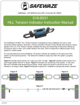
Fall Clearance Diagram
***Diagram shown is an EXAMPLE how
to calculate clear fall requirements.
For all applications: Worker Weight Max Capacity for a Single
User (including all clothing, tools, and equipment) is 420 lbs.
Capacity range for 2 Users is (130-310 lbs) for each User
(including all clothing, tools , and equipment)
FIGURE 1 - FALL CLEARANCE CALCULATION DIAGRAM
Fall Clearance: There must be sucient clearance below the anchorage connector
to arrest a fall before the user strikes the next lower level, or an obstruction. When
calculating fall clearance, account for a MINIMUM 2’ safety factor, deceleration
distance, user height, length of Lanyard/SRL, and all other applicable factors
(See Figure 1).
5.0 Limitations
A
FALL-ARREST
A
FALL-ARREST
A
G
B
C
D
E
F
ADeployed Integral Energy Absorber
BDynamic Lifeline Sag
CDeployed Energy Absorbing Lanyard
DHarness Stretch
EHeight Of Worker
FSafety Factor
GTotal Required Fall Clearance

User Manual
V1.8 2022 Copyright Safewaze
Connectors are compatible with connecting elements when they have been designed
to work together in such a way that their sizes and shapes do not cause their
gate mechanisms to inadvertently open regardless of how they become oriented.
Connectors (hooks, carabiners, and D-rings) must be capable of supporting at least
5,000 lbs. (22.2 kN). Connectors must be compatible with the anchorage or other
system components (See Figure 4). Do not use equipment that is not compatible.
Non-compatible connectors may unintentionally disengage (See Figure 3). Connectors
must be compatible in size, shape, and strength. Self-locking snap hooks and
carabiners are required by ANSI Z359 and OSHA guidelines. Contact Safewaze
if you have any questions about compatibility.
FIGURE 3 - UNINTENTIONAL DISENGAGEMENT
NOTE: SOME SPECIALITY CONNECTORS HAVE ADDITIONAL REQUIREMENTS.
CONTACT Safewaze WITH QUESTIONS.
FIGURE 2 - SWING FALL
Using a connector that is undersized or irregular in shape (1) to connect a snap hook
or carabiner could allow the connector to force open the gate of the snap hook or
carabiner. When force is applied, the gate of the hook or carabiner presses against
the non-compliant part (2) and forces open the gate (3). This allows the snap hook or
carabiner to disengage (4) from the connection point.
Page 5
6.0 Compatibility Of Connections
A
FALL-ARREST
3 - Gate opens
2 - Gate presses
against
non-complaint
part
4 - Parts disengage.1 - Non-compliant part

User Manual
V1.8 2022 Copyright Safewaze Page 6
7.0 Making Connections
Snap hooks and carabiners used with this equipment must be double locking and/
or twist lock. Ensure all connections are compatible in size, shape and strength. Do
not use equipment that is not compatible. Ensure all connectors are fully closed and
locked.
Safewaze connectors (snap hooks and carabiners) are designed to be used only
as specied in each product’s user’s instructions. See gure 4 for examples of
inappropriate connections. Do not connect snap hooks and carabiners:
• To a D-ring to which another connector is attached.
• In a manner that would result in a load on the gate (with the exception of tie back
hooks).
NOTE: Large throat snap hooks must not be connected to standard size D-rings or
similar objects which will result in a load on the gate if the hook or D-ring twists or
rotates, unless the snap hook complies with ANSI Z359.1-2007 or ANSI Z359.12 and is
equipped with a 3,600 lb (16 kN) gate. Check the marking on your snap hook to verify
that it is appropriate for your application.
• In a false engagement, where features that protrude from the snap hook or
carabiner catch on the anchor, and without visual conrmation seems to be fully
engaged to the anchor point.
• To each other.
• By wrapping the web lifeline around an anchor and securing to lifeline except as
allowed for Tie Back models.
• To any object which is shaped or sized in a way that the snap hook or carabiner will
not close and lock, or that roll-out could occur.
• In a manner that does not allow the connector to align properly while under load.
FIGURE 4 - INAPPROPRIATE CONNECTIONS
• NOTE: Large snap hooks must not be connected to objects which will result in a
load on the gate if the hook twists or rotates, unless the snap hook complies with
ANSI Z359.1-2007 or ANSI Z359.12 and is equipped with a 3,600 lb (16 kN) gate.
Check the marking on your snap hook to verify its compatibility.

User Manual
V1.8 2022 Copyright Safewaze Page 7
7.1 Connections
Number of Users:
Maximum two users at one time with a capacity up to 310 lbs. per worker including
tools and equipment.
Maximum one user at one time with a capacity up to 420 lbs. per worker including tools
and equipment.
Full Body Harnesses
Only Full Body Harnesses may be used with a Safewaze Kernmantle Rope Horizontal
Lifeline.
Use of Energy Absorbing Lanyards (EALs)
Fall Clearance Requirements when utilizing a 6’ Energy Absorbing Lanyard with the
HLL system are indicated in the fall clearance table in Section 10, page 14 of this
manual. The fall clearance distances indicated are the total required from the properly
installed HLL system to the next lower level or obstruction. The user should ensure
that the distance between the installed lifeline and the next lower level is at least equal
to, or greater than the values given in Section 10, page 14 of this manual prior to use of
the HLL system. Failure to calculate proper fall clearances prior to use of the system
could result in serious injury or death.
Note: Never use combinations of components or subsystems that may aect, or
interfere with the safe function of each other.
Use of Self-Retracting Lifelines (SRLs)
Fall Clearance Requirements when utilizing an SRL with the HLL system in an
overhead installation are indicated in the fall clearance table in Section 10.1, page 15
of this manual. When using Personal SRL’s with the HLL system, where the
installation could possibly be below dorsal D-ring Height, refer to the fall clearance
table in Section 10.2, page 16 of this manual. The user must ensure that the
Personal SRL being utilized is not connected to the HLL at a distance below the dorsal
D-ring, which exceeds the maximum allowed as specied by the SRL manufacturer.
When calculating fall clearance distances, the user must add the total deection of
the HLL system during a fall event, to the total deceleration distance of the SRL being
used. The combination of the system deection, and the deceleration distance of the
SRL, when added to the Harness Stretch of the full body harness, worker’s height, and
Safety Factor equals the minimum required fall clearance. Failure to calculate proper
fall clearances prior to use of the system could result in serious injury or death.

User Manual
V1.8 2022 Copyright Safewaze Page 8
8.0 Components and Specifications
Part
Number
Length in
Feet
019-8000 30 ft.
019-8001 60 ft.
019-8002 80 ft.
019-8003 100 ft
Part
Number
Length in
Feet
019-8004 30 ft.
019-8005 60 ft.
019-8006 80 ft.
019-8007 100 ft
Part
Number
Length in
Feet
019-8008 30 ft.
019-8009 60 ft.
019-8010 80 ft.
019-8011 100 ft
FIGURE 5 - HLL KIT PART NUMBERS AND CONFIGURATIONS
Conguration 1 Conguration 2 Conguration 3
Safewaze Kernmantle Rope Horizontal Lifelines are oered in three dierent
congurations. Four lengths are oered in each conguration. The tables above
indicate the part numbers and system lengths oered in each conguration.
Conguration 1 is a complete Kernmantle Rope Horizontal Lifeline system but does
not include anchorage connectors. Conguration 2 is a complete HLL system, and
includes two Safewaze FS810-6 Cross Arm Straps for anchorage connection
(See Figure 6). Conguration 3 is a complete HLL system, and includes two Safewaze
018-4000 Chain Anchors for anchorage connection (See Figure 7).

User Manual
V1.8 2022 Copyright Safewaze Page 9
The entire Safewaze Kernmantle Rope Horizontal Lifeline system, and its subsystems,
must be inspected prior to each use for wear, damage, and other deterioration. All
snaphooks and carabiners must be able to self-close and lock. Check the operation
of self retracting lifelines by pulling smoothly on the lifeline, then pull sharply on the
lifeline to engage the locking mechanism. All webbing and rope must be inspected
for tears, cuts, fraying, abrasion, unsplicing, discoloration, or other signs of wear and
damage. Sewn terminations should be secure, complete, and not visibly damaged. All
rope splices should be secure. System must be properly tensioned. No load indicators
shall be deployed. Damaged and other deteriorated and defective components must
be immediately removed from service, in accordance with the requirements of OSHA
29 CFR 1910.66 and 1926.502.
019718
Typical Installation
Max. 100 Ft Span Length
In -Line Shock Absorber
Cross-Arm Strap
Attachment O-Ring for User (Lanyard)
Anchorage
Carabiner
Rope Tensioner
Rope
FIGURE 6 - CROSS ARM STRAP INSTALLATION EXAMPLE
9.0 Installation and Use
Before Each Use
Users of personal fall arrest systems must have a rescue plan in place, if the user
cannot rescue themselves, as well as the means to carry out the rescue.
The user must read and understand these User Instructions, as well as the User
Instructions for every component/subsystem of the personal fall arrest system.
Cross Arm Strap System Installation
Step 1. Install Anchorage Connector
Wrap the Cross Arm Strap around the anchorage and pass the small D-ring end
through the large D-ring end. Wrap as many times as necessary to achieve desired
length, ensuring strap is wrapped at least twice around the end anchorage. A
minimum of two wraps around the end anchorage helps prevent sliding of the anchor
straps during use. Only connect to the small D-ring of the Cross Arm Strap.
Other approved anchorage connectors may be used in place of the supplied Cross Arm
Strap. See anchorage connector user instructions for proper installation.

User Manual
V1.8 2022 Copyright Safewaze
Step 2. Connect Thimble End of Rope
Connect the Thimble End of the rope lifeline to the small D-ring of the Cross Arm Strap
using the supplied carabiner.
Step 3. Connect In-Line Energy Absorber
Attach the In-Line Energy Absorber (Energy Absorber is pre-attached to Rope Tensioner)
to the remaining end anchorage connector via the other supplied carabiner. Be sure to
connect to the small D-ring of the Cross Arm Strap
Step 4. Tension the System
Place the locking lever in the closed position so that it is engaged (See Figure 9A).
Remove the slack from the system by pulling the pre-installed rope through the
tensioner by hand until the slack has been removed from the system. Use a 1-1/4”
wrench or metal bar (See Figure 9D) to turn ratchet in the direction of the arrow until
wheel slips or no longer rotates. Final tension on the system should be approximately
200-250 lbs. Do not over tension the system or alter the tensioner to achieve greater
tension (See Figure 9E).
Step 5. Connect to System
Once properly tensioned, connect a PFAS system only to the connection O-rings
preinstalled on the lifeline.
Page 10
FIGURE 7 - CHAIN ANCHOR INSTALLATION EXAMPLE
019719
Typical Installation
Max. 100 Ft Span Length
In -Line Shock Absorber
018-4000 Chain Anchor
Attachment O-Ring for User (Lanyard)
Anchorage
Carabiner
Rope Tensioner
Rope
Chain Anchor System Installation
Step 1. Install Anchorage Connector
Under guidance of a Competent or Qualied Person, a suitable anchor point must be
chosen that meets the strength requirement, minimizes free fall, and reduces swing
fall hazards. Do not work above the anchorage point.The 018-4000 Chain Anchor can
be mounted at the peak of a roof structure with one mounting plate on each side of
the peak, or mounted at on the roof perpendicular to the peak. In either instance, the
Chain Anchor must be mounted to the roof structure through the sheathing and into a
joist via the supplied (6) 5/16” x 3” lag bolts, or with (12) customer supplied 16D Nails.
All fasteners must be fully embedded into sheathing and joist (See Figure 8). The
018-4000 Chain Anchor can be removed and re-used unless the Chain Anchor is

User Manual
V1.8 2022 Copyright Safewaze Page 11
damaged or has experienced Fall Arrest Forces. If either of these conditions exist,
the Chain Anchor must IMMEDIATELY be removed from service and destroyed.
Other approved anchorage connectors, which meet the 5,000 lbs strength requirement,
may be used in place of the supplied 018-4000 Chain Anchors. See anchorage
connector user instructions for proper installation.
Step 2. Connect Thimble End of Rope
Connect the Thimble End of the rope lifeline to the small O-ring of the Chain Anchor us-
ing the supplied carabiner.
Step 3. Connect In-Line Energy Absorber
Attach the In-Line Energy Absorber (Energy Absorber is pre-attached to Rope Tensioner)
to the remaining end anchorage connector via the other supplied carabiner. Be sure to
connect to the small D-ring of the Cross Arm Strap
Step 4. Tension the System
Place the locking lever in the closed position so that it is engaged (See Figure 9A).
Remove the slack from the system by pulling the pre-installed rope through the
tensioner by hand until the slack has been removed from the system. Use a 1-1/4”
wrench or metal bar (See Figure 9D) to turn ratchet in the direction of the arrow until
wheel slips or no longer rotates. Final tension on the system should be approximately
200-250 lbs. Do not over tension the system or alter the tensioner to achieve greater
tension (See Figure 9E).
Step 5. Connect to System
Once properly tensioned, connect a PFAS system only to the connection O-rings
preinstalled on the lifeline.
FIGURE 8 - CHAIN ANCHOR INSTALLATION
SHEATHING
LAG BOLT
LAG BOLT
TRUSS

User Manual
V1.8 2022 Copyright Safewaze Page 12
FIGURE 9 - ROPE TENSIONER OPERATION
Tensioner with Locking Lever Closed Tensioner with Locking Lever Open
Use a wrench or
cylindrical bar to turn
tensioning nut.
Turn Bar/Wrench to put more tension
on the rope.
Tension rope until wheel slips or no
longer rotates
Specications:
-Plated Steel
-Designed to be used with the Safewaze Kernmantle Rope Horizontal Lifeline System
-Weight: 3.6 lbs
-Minimum Break Strength of 16mm Kernmantle Rope 9,807 lbs.
Meets all OSHA requirements
Tensioning Nut
A B
C D E

User Manual
V1.8 2022 Copyright Safewaze Page 13
FIGURE 11 - COMPONENTS
Max. 100 Ft Span Length
A
G
CD
E
F
B
FIGURE 10 - RELEASING LIFELINE TENSION
Once work operations are complete, work requires movement of HLL system to
another location, or the system needs to be uninstalled, the lifeline tension will
need to be released. To release the tension:
Step 1. Lift the locking lever to a position where a bar or wrench can be inserted
between the locking lever and the body of the tensioner.
Step 2. Using the bar or wrench, pry the locking lever open to release the tension on
the lifeline.
Step 3. Loosen the tensioning nut with the bar or wrench by turning the tensioning nut
counter clockwise until loose.
Step 4. The rope can be pulled through the tensioner by hand if necessary, by holding
the locking lever in the disengaged position and pulling the rope through the tensioner.
Tensioning Nut
Wrench or Bar Locking Lever
The Safewaze Kernmantle Horizontal Lifeline is designed as a temporary reusable
anchorage subsystem for attachment of up to two Personal Fall Arrest systems.
The Kernmantle Horizontal Lifeline subsystem is comprised of 32 strand, 12,000 lbs.
tensile strength 11/16” (17mm) diameter nylon Kernmantle rope with a stitched
thimble connection eye on one end and a rope tensioning device on the other. The
system also contains an in-line energy absorber and two self-closing, self-locking,
ANSI Z359.12 compliant end attachment carabiners. One carabiner is attached to the
thimble eye, and one is attached to the rope tensioning device. The rope tensioning
device is a plated steel tensioner through which the kernmantle rope is threaded and
then stitch terminated to prevent removal of the rope from the tensioner.
A
B
C
D
E
F
G
Carabiner
O-Rings
Rope
Rope Tensioner
In Line Shock Absorber
Cross Arm Strap
Anchorage

User Manual
V1.8 2022 Copyright Safewaze
6 ft. Energy Absorbing Lanyard Fall
Clearance Chart
(1 User)
420 lbs. Max Capacity
6 ft. Energy Absorbing Lanyard
Fall Clearance Chart
(2 Users)
310 lbs. Max Capacity per User
Page 14
10.0 Fall Clearance Charts
A
FALL-ARREST
0-30
(0-9.14)
31-40
(9.44-12.20)
41-50
(12.50-15.24)
51-60
(15.54-18.28)
61-70
(18.60-21.33)
71-80
(21.64-24.38)
81-90
(24.68-27.43)
91-100
(27.73-30.48)
17
(5.18)
18.5
(5.63)
20.0
(6.09)
21.5
(6.55)
24.0
(7.31)
25.5
(7.77)
27.0
(8.22)
29.0
(8.83)
18.0
(5.48)
19.5
(5.94)
21.0
(6.40)
22.5
(6.85)
25.0
(7.62)
26.5
(8.07)
28.0
(8.53)
30.0
(9.14)
19.0
(5.79)
20.5
(6.24)
22.0
(6.70)
23.5
(7.16)
26.0
(7.92)
27.5
(8.38)
29.0
(8.83)
31.0
(9.44)
20.0
(6.09)
21.5
(6.55)
23.0
(7.01)
24.5
(7.46)
27.0
(8.22)
28.5
(8.68)
30.0
(9.14)
32.0
(9.75)
21.0
(6.40)
22.5
(6.85)
24.0
(7.31)
25.5
(7.77)
28.0
(8.53)
29.5
(8.99)
31.0
(9.44)
33.0
(10.05)
22.0
(6.70)
23.5
(7.16)
25.0
(7.62)
26.5
(8.07)
29.0
(8.83)
30.5
(9.29)
32.0
(9.75)
34.0
(10.36)
23.0
(7.01)
24.5
(7.46)
26
(7.92)
27.5
(8.38)
30.0
(9.14)
31.5
(9.60)
33.0
(10.05)
35.0
(10.66)
0 1 2 3 4 5 6
Freefall Distance in Feet
Span Length in Feet (m)
0-30
(0-9.14)
31-40
(9.44-12.20)
41-50
(12.50-15.24)
51-60
(15.54-18.28)
61-70
(18.60-21.33)
71-80
(21.64-24.38)
81-90
(24.68-27.43)
91-100
(27.73-30.48)
20.0
(6.09)
21.5
(6.55)
24.0
(7.31)
25.5
(7.77)
32.5
(9.90)
32.5
(9.90)
34.5
(10.51)
34.5
(10.51)
34.5
(10.51)
21.0
(6.40)
22.5
(6.85)
25.0
(7.62)
26.5
(8.07)
28.0
(8.53)
35.5
(10.82)
35.5
(10.82)
35.5
(10.82)
22.0
(6.70)
23.5
(7.16)
26.0
(7.92)
27.5
(8.38)
29.0
(8.83)
36.5
(11.12)
36.5
(11.12)
36.5
(11.12)
23.0
(7.01)
24.5
(7.46)
27.0
(8.22)
28.5
(8.68)
33.5
(10.21)
33.5
(10.21)
37.5
(11.43)
37.5
(11.43)
24.0
(7.31)
25.5
(7.77)
28.0
(8.53)
29.5
(8.99)
31.0
(9.44)
38.5
(11.73)
38.5
(11.73)
25.0
(7.62)
26.5
(8.07)
29.0
(8.83)
30.5
(9.29)
30.5
(9.29)
32.0
(9.75)
39.5
(12.03)
26
(7.92)
27.5
(8.38)
30.0
(9.14)
30.0
(9.14)
31.5
(9.60)
31.5
(9.60)
34.0
(10.36)
33.0
(10.05)
40.5
(12.34)
0 1 2 3 4 5 6
Freefall Distance in Feet
Span Length in Feet (m)

User Manual
V1.8 2022 Copyright Safewaze Page 15
Span Length In
Feet
(m)
Fall Clearance with
SafeWaze SRL in
Feet
(m)
Fall Clearance with
SafeWaze SRL in
Feet
(m)
Safewaze Required Fall Clearance for Up to 2 Users
Maximum Span 100 ft.
0-30
(0-9.14)
31-40
(9.44-12.20)
41-50
(12.50-15.24)
51-60
(15.54-18.28)
61-70
(18.60-21.33)
71-80
(21.64-24.38)
81-90
(24.68-27.43)
91-100
(27.73-30.48)
ONE USER TWO USERS
14.0
(4.26)
15.5
(4.72)
16.5
(5.02)
18.5
(5.63)
19.5
(5.94)
21.0
(6.40)
22.0
(6.70)
23.5
(7.16)
17.0
(5.18)
18.0
(4.48)
19.0
(5.79)
20.5
(6.24)
22.0
(6.70)
23.0
(7.01)
24.0
(7.31)
25.5
(7.77)
A
FALL-ARREST
WWW.SAFEWAZE.COM
SELF RETRACTING LANYARD
SELF RETRACTING LANYARD
ANSI Z359.14 & ANSI A10.32
OSHA 1910.66 & OSHA 1926.502
Fall Arrest Systems • Confined Space • Engineering • Rescue Systems
6’
6’
Fall Clearance Chart
Class A SRL
Fall Clearance Chart
Class B SRL
Span Length In
Feet
(m)
Fall Clearance with
SafeWaze SRL in
Feet
(m)
Fall Clearance with
SafeWaze SRL in
Feet
(m)
Safewaze Required Fall Clearance for Up to 2 Users
Maximum Span 100 ft.
0-30
(0-9.14)
31-40
(9.44-12.20)
41-50
(12.50-15.24)
51-60
(15.54-18.28)
61-70
(18.60-21.33)
71-80
(21.64-24.38)
81-90
(24.68-27.43)
91-100
(27.73-30.48)
ONE USER TWO USERS
16.5
(5.02)
18.0
(5.48)
19.0
(5.79)
21.0
(6.40)
22.0
(6.70)
23.5
(7.16)
24.5
(7.46)
26.0
(7.92)
19.5
(5.94)
20.5
(6.24)
21.5
(6.55)
23.0
(7.01)
24.5
(7.46)
25.5
(7.77)
26.5
(8.07)
28.0
(8.53)
10.1 Fall Clearance Charts
**THESE CLEARANCE CHARTS REQUIRE THAT THE SRL IS OVER THE HEAD OF THE WORKER WHEN
ATTACHED TO THE HORIZONTAL LIFELINE
Overhead SRL Usage
Fall Clearance Chart
(1 To 2 Users)

User Manual
V1.8 2022 Copyright Safewaze Page 16
10.2 Fall Clearance Charts
A
FALL-ARREST
WWW.SAFEWAZE.COM
SELF RETRACTING LANYARD
SELF RETRACTING LANYARD
ANSI Z359.14 & ANSI A10.32
OSHA 1910.66 & OSHA 1926.502
Fall Arrest Systems • Confined Space • Engineering • Rescue Systems
6’
6’
0-30
(0-9.14)
31-40
(9.44-12.20)
41-50
(12.50-15.24)
51-60
(15.54-18.28)
61-70
(18.60-21.33)
71-80
(21.64-24.38)
81-90
(24.68-27.43)
91-100
(27.73-30.48)
17
(5.18)
18.5
(5.63)
20.0
(6.09)
21.5
(6.55)
24.0
(7.31)
25.5
(7.77)
27.0
(8.22)
29.0
(8.83)
18.0
(5.48)
19.5
(5.94)
21.0
(6.40)
22.5
(6.85)
25.0
(7.62)
26.5
(8.07)
28.0
(8.53)
30.0
(9.14)
19.0
(5.79)
20.5
(6.24)
22.0
(6.70)
23.5
(7.16)
26.0
(7.92)
27.5
(8.38)
29.0
(8.83)
31.0
(9.44)
20.0
(6.09)
21.5
(6.55)
23.0
(7.01)
24.5
(7.46)
27.0
(8.22)
28.5
(8.68)
30.0
(9.14)
32.0
(9.75)
21.0
(6.40)
22.5
(6.85)
24.0
(7.31)
25.5
(7.77)
28.0
(8.53)
29.5
(8.99)
31.0
(9.44)
33.0
(10.05)
22.0
(6.70)
23.5
(7.16)
25.0
(7.62)
26.5
(8.07)
29.0
(8.83)
30.5
(9.29)
32.0
(9.75)
34.0
(10.36)
0 1 2 3 4 5
Freefall Distance in Feet
Span Length in Feet (m)
Personal SRL Usage
At or Below Dorsal D-ring Height
Fall Clearance Chart
(2 Users)

User Manual
V1.8 2022 Copyright Safewaze Page 17
Maintenance
Any Safewaze Kernmantle Rope Horizontal Lifeline components requiring
maintenance must be tagged “unusable” and removed from service.
Cleaning maintenance may be performed by the user.
Repairs to the product may only be made by the manufacturer or entities authorized in
writing by the manufacturer.
THIS SYSTEM MUST BE INSPECTED BY A TRAINED COMPETENT INDIVIDUAL OR Safewaze!
NEVER ATTEMPT TO SERVICE THIS UNIT OR TAMPER WITH ITS FUNCTION IN ANY WAY!
Storage
When not installed, the Safewaze Horizontal Lifeline should be stored in a cool, dry
place out of direct sunlight. Do not store in areas where damage from environmental
factors such as heat, light, excessive moisture, oil, chemicals and their vapors, or other
degrading elements may be present. Do not store damaged equipment or equipment
in need of maintenance in the same area as product approved for use. Equipment that
has been stored for an extended period must be inspected as described in these User
Instructions prior to use.
11.0 Inspection and Maintenance
Inspection
Inspect the device for corrosion and/or damage.
Check the Housing Plates for signs of distortion.
Inspect both the webbing of Cross Arm Straps (if being used) and Rope for cuts,
abrasions and contamination.
Check carabiners for proper operation, signs of corrosion, distortion or damage.
Frequency
All components of the Safewaze Kernmantle Rope Horizontal Lifeline must be
inspected prior to each use, and annually by a “competent person” (other than the
user), as dened by OSHA.
Criteria
If inspection reveals any defect, inadequate maintenance, or unsafe condition, remove
from service until a “qualied person” as dened by OSHA 1926.32(m) can determine
the need for authorized repair or disposal.

User Manual
V1.8 2022 Copyright Safewaze
13.0 Inspection Log
Page 18
DATE CONDITION OF SYSTEM INSPECTED BY:
12.0 Labels
WARNING
Manufacturer’s instructions supplied with this product at time of shipment must be
read and understood prior to use. Ensure Horizontal Lifeline is installed at an
elevations which will limit Free Falls to a maximum of 6 feet when using Energy
Absorbing Lanyards, and installed overhead when using Self Retracting Lifelines.
This equipment must be installed under the supervision of a Qualified Person.
Inspect all connections prior to use and verify connecting components are installed
correctly. Failure to make secure connections could result in serious injury or death.
Not flame or heat resistant. Avoid contact with sharp and abrasive edges. Caution
should be taken using this equipment near Hazardous Thermal, Electrical, or
Chemical Sources. Equipment exposed to fall arrest forces should be immediately
removed from service. Alteration or misuse of this product, or failure to follow
instructions could lead to serious injury or death. DO NOT REMOVE THIS LABEL.
019702

User Manual
V1.8 2022 Copyright Safewaze
WARRANTY
Safewaze
225 Wilshire Ave SW
Concord, NC 28025
PHONE: 1-800-230-0319
FAX: 1-704-262-9051
EMAIL: [email protected]
Web: Safewaze.com
Page 19
/