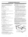
Bauknecht LI3VQA Owner's manual
- Category
- Cooker hoods
- Type
- Owner's manual

30" (76.2 CM) AND 36" (91.4 CM) RANGE HOOD
Installation Instructions and Use & Care Guide
HOTTE D’ASPIRATION DE
30" (76,2 CM) ET 36" (91,4 CM)
Instructions d’installation et Guide d’utilisation et d’entretien
Table of Contents/Table des matières.............................................................................2
IMPORTANT: READ AND SAVE THESE INSTRUCTIONS.
FOR RESIDENTIAL USE ONLY.
IMPORTANT : LIRE ET CONSERVER CES INSTRUCTIONS.
POUR UTILISATION RÉSIDENTIELLE UNIQUEMENT.
LI3VQB/W10274302C

2
TABLE OF CONTENTS
RANGE HOOD SAFETY .................................................................2
INSTALLATION REQUIREMENTS................................................3
Tools and Parts ............................................................................3
Location Requirements................................................................4
Venting Requirements..................................................................5
Electrical Requirements ...............................................................6
INSTALLATION INSTRUCTIONS..................................................7
Prepare Location..........................................................................7
Install Range Hood.......................................................................9
Complete Installation .................................................................10
RANGE HOOD USE......................................................................10
Range Hood Controls ................................................................11
RANGE HOOD CARE...................................................................11
Cleaning......................................................................................11
WIRING DIAGRAM ......................................................................12
ASSISTANCE OR SERVICE.........................................................13
In the U.S.A. ...............................................................................13
In Canada ...................................................................................13
Accessories................................................................................13
WARRANTY ..................................................................................14
TABLE DES MATIÈRES
SÉCURITÉ DE LA HOTTE DE CUISINIÈRE ...............................15
EXIGENCES D'INSTALLATION...................................................17
Outils et pièces...........................................................................17
Exigences d'emplacement.........................................................17
Exigences concernant l'évacuation ...........................................18
Spécifications électriques ..........................................................20
INSTRUCTIONS D'INSTALLATION.............................................21
Préparation de l'emplacement...................................................21
Installation de la hotte ................................................................22
Achever l’installation ..................................................................24
UTILISATION DE LA HOTTE .......................................................24
Commandes de la hotte de cuisinière .......................................24
ENTRETIEN DE LA HOTTE..........................................................25
Nettoyage ...................................................................................25
SCHÉMA DE CÂBLAGE...............................................................26
ASSISTANCE OU SERVICE.........................................................27
Au Canada..................................................................................27
Accessoires ................................................................................27
GARANTIE.....................................................................................27
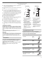
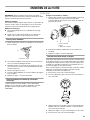
RANGE HOOD SAFETY
You can be killed or seriously injured if you don't immediately
You
can be killed or seriously injured if you don't
follow
All safety messages will tell you what the potential hazard is, tell you how to reduce the chance of injury, and tell you what can
happen if the instructions are not followed.
Your safety and the safety of others are very important.
We have provided many important safety messages in this manual and on your appliance. Always read and obey all safety
messages.
This is the safety alert symbol.
This symbol alerts you to potential hazards that can kill or hurt you and others.
All safety messages will follow the safety alert symbol and either the word “DANGER” or “WARNING.”
These words mean:
follow instructions.
instructions.
DANGER
WARNING

3
INSTALLATION REQUIREMENTS
Tools and Parts
Gather the required tools and parts before starting installation.
Read and follow the instructions provided with any tools listed
here.
Tools needed
■ Drill
■ 1¹⁄₄" (3.0 cm) drill bit
■ ¹⁄₈" (3.0 mm) drill bit for pilot holes
■ Pencil
■ Wire stripper or utility knife
■ Tape measure or ruler
■ Caulking gun and weatherproof caulking compound
■ Flat-blade screwdriver
■ Phillips screwdriver
For vented installations, you also need:
■ Saber or keyhole saw
■ Vent clamps
■ Metal snips
■ Compass or 8" (20.3 cm) circle template
Parts supplied
Remove parts from package. Check that all parts are included.
■ 2 - Metal filters
■ 6 - 4.5 x 13 mm mounting screws
■ 3 - 4 x 8 mm damper screws
■ 3¹⁄₄" x 10" (8.3 x 25.4 cm) damper/vent connector
IMPORTANT SAFETY INSTRUCTIONS
READ AND SAVE THESE INSTRUCTIONS
WARNING: TO REDUCE THE RISK OF FIRE, ELECTRIC
SHOCK, OR INJURY TO PERSONS, OBSERVE THE
FOLLOWING:
■ Use this unit only in the manner intended by the
manufacturer. If you have questions, contact the
manufacturer.
■ Before servicing or cleaning the unit, switch power off at
service panel and lock the service disconnecting means to
prevent power from being switched on accidentally. When
the service disconnecting means cannot be locked,
securely fasten a prominent warning device, such as a tag,
to the service panel.
■ Installation work and electrical wiring must be done by
qualified person(s) in accordance with all applicable codes
and standards, including fire-rated construction.
■ Do not operate any fan with a damaged cord or plug.
Discard fan or return to an authorized service facility for
examination and/or repair.
■ Sufficient air is needed for proper combustion and
exhausting of gases through the flue (chimney) of fuel
burning equipment to prevent backdrafting. Follow the
heating equipment manufacturer's guideline and safety
standards such as those published by the National Fire
Protection Association (NFPA), the American Society for
Heating, Refrigeration and Air Conditioning Engineers
(ASHRAE), and the local code authorities.
■ When cutting or drilling into wall or ceiling; do not damage
electrical wiring and other utilities.
■ Ducted fans must always be vented outdoors.
CAUTION: For general ventilating use only. Do not use
to exhaust hazardous or explosive materials and vapors.
CAUTION: To reduce risk of fire and to properly exhaust
air, be sure to duct air outside - do not vent exhaust air into
spaces within walls or ceilings, attics or into crawl spaces,
or garages.
WARNING: TO REDUCE THE RISK OF FIRE, USE ONLY
METAL DUCTWORK.
WARNING: TO REDUCE THE RISK OF A RANGE TOP
GREASE FIRE:
■ Never leave surface units unattended at high settings.
Boilovers cause smoking and greasy spillovers that may
ignite. Heat oils slowly on low or medium settings.
■ Always turn hood ON when cooking at high heat or when
flambeing food (i.e. Crepes Suzette, Cherries Jubilee,
Peppercorn Beef Flambé).
■ Clean ventilating fans frequently. Grease should not be
allowed to accumulate on fan or filter.
■ Use proper pan size. Always use cookware appropriate for
the size of the surface element.
WARNING: TO REDUCE THE RISK OF INJURY TO
PERSONS IN THE EVENT OF A RANGE TOP GREASE
FIRE, OBSERVE THE FOLLOWING:
a
■ SMOTHER FLAMES with a close fitting lid, cookie sheet, or
metal tray, then turn off the burner. BE CAREFUL TO
PREVENT BURNS. If the flames do not go out
immediately, EVACUATE AND CALL THE FIRE
DEPARTMENT.
■ NEVER PICK UP A FLAMING PAN - you may be burned.
■ DO NOT USE WATER, including wet dishcloths or towels -
a violent steam explosion will result.
■ Use an extinguisher ONLY if:
– You know you have a class ABC extinguisher, and you
already know how to operate it.
– The fire is small and contained in the area where it
started.
– The fire department is being called.
– You can fight the fire with your back to an exit.
a
Based on "Kitchen Fire Safety Tips" published by NFPA.
■ WARNING: To reduce the risk of fire or electrical shock,
do not use this fan with any solid-state speed control
device.

4
■ 4 - 5 x 45 mm screws
■ 4 - 8 x 40 mm wall anchors
■ Recirculating kit
■ Charcoal filters for non-vented (recirculating) installations.
See the “Assistance or Service” section to order replacement
filters.
Parts needed
For vented installations:
■ 3¹⁄₄" x 10" (8.3 x 25.4 cm) or 6" (15.2 cm) or larger round metal
venting
■ 6" (15.2 cm) or larger round damper, if using 6" (15.2 cm) or
larger round vent system
■ 3¹⁄₄" x 10" (8.3 x 25.4 cm) to 6" (15.2 cm) or larger diameter
transition piece if using 6" (15.2 cm) or larger diameter round
vent system.
For cabinets with recessed bottoms:
■ Two 2" (5.1 cm) wide filler strips. Length and thickness
determined by recess dimensions.
■ Four flat head wood screws or machine screws with washers
and nuts (to attach filler strips).
Location Requirements
IMPORTANT: Observe all governing codes and ordinances.
■ It is the installer’s responsibility to comply with installation
clearances specified on the model/serial rating plate. The
model/serial rating plate is located inside the range hood on
the left wall.
■ Range hood location should be away from strong draft areas,
such as windows, doors and strong heating vents.
■ Cabinet opening dimensions that are shown must be used.
Given dimensions provide minimum clearance. Consult the
cooktop/range manufacturer installation instructions before
making any cutouts.
■ Grounded electrical outlet is required. See “Electrical
Requirements” section.
■ The hood is factory-set for vented installations. For non-
vented (recirculating) installations, the Recirculation Kit is
included. See the “Assistance or Service” section to order
Replacement Charcoal Filters Part Number W10272068.
■ All openings in ceiling and wall where range hood will be
installed must be sealed.
For Mobile Home Installations
The installation of this range hood must conform to the
Manufactured Home Construction Safety Standards, Title 24
CFR, Part 328 (formerly the Federal Standard for Mobile Home
Construction and Safety, title 24, HUD, Part 280) or when such
standard is not applicable, the standard for Manufactured Home
Installation 1982 (Manufactured Home Sites, Communities and
Setups) ANSI A225.1/NFPA 501A*, or latest edition, or with local
codes.
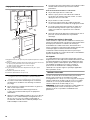
Product Dimensions
Installation Clearances
A. 18" (45.7 cm) min. clearance - upper cabinet to countertop
B. 24" (61.0 cm) min. for electric cooking surfaces
27" (68.6 cm) min. for gas cooking surfaces
30" (76.2 cm) suggested max. - bottom of range hood to
cooking surface
C. 30" (76.2 cm) or 36" (91.4 cm) min. cabinet opening width
D. 13" (33.0 cm) cabinet depth
E. 36" (91.4 cm) base cabinet height
29 ⁷⁄₈" (75.9 cm) - 30" (76.2 cm) model
35 ⁷⁄₈" (91.1 cm) - 36" (91.4 cm) model
1³⁄₁₆"
(3.0 cm)
2"
(5.1 cm)
12"
(30.5 cm)
7¹⁄₄"
(18.4 cm)
9"
(22.9 cm)
⁵⁄₈"
(1.6 cm)
⁵⁄₈"
(1.6 cm)
19
³⁄₄
"
(50.2 cm)
3" (7.6 cm) -
30" (76.2 cm) model
5 ³⁄₄" (14.6 cm) -
36" (91.4 cm) model
A
B
C
D
E

5
Venting Requirements
(Vented Models Only)
■ Vent system must terminate to the outdoors, except for non-
vented (recirculating) installations.
■ Do not terminate the vent system in an attic or other enclosed
area.
■ Do not use a 4" (10.2 cm) laundry-type wall cap.
■ Use a 6" (15.2 cm) or larger round metal vent or a 3¹⁄₄" x 10"
(8.3 x 25.4 cm) rectangular metal vent. Rigid metal vent is
recommended. Plastic or metal foil vent is not recommended.
■ The length of vent system and number of elbows should be
kept to a minimum to provide efficient performance.
For the most efficient and quiet operation:
■ Use no more than three 90° elbows.
■ Make sure there is a minimum of 24" (61 cm) of straight vent
between the elbows if more than 1 elbow is used.
■ Do not install 2 elbows together.
■ Use clamps to seal all joints in the vent system.
■ The vent system must have a damper. If roof or wall cap has a
damper, do not use damper supplied with the range hood.
■ Use caulking to seal exterior wall or roof opening around the
cap.
Cold Weather Installations
An additional back draft damper should be installed to minimize
backward cold air flow and a thermal break should be installed to
minimize conduction of outside temperatures as part of the vent
system. The damper should be on the cold air side of the thermal
break.
The break should be as close as possible to where the vent
system enters the heated portion of the house.
Makeup Air
Local building codes may require the use of make up air systems
when using ventilation systems greater than specified CFM of air
movement. The specified CFM varies from locale to locale.
Consult your HVAC professional for specific requirements in your
area.
Venting Methods
Vent system can terminate either through the roof or wall. Use
3¹⁄₄" x 10" (8.3 x 25.4 cm) with a maximum vent length of
35 ft (10.7 m) or 6" (15.2 cm) or larger round vent with a maximum
length of 50 ft (15.2 m) for vent system.
NOTE: Flexible vent is not recommended. Flexible vent creates
back pressure and air turbulence that gently reduces
performance.
Calculating Vent System Length
To calculate the length of the system you need, add the
equivalent feet (meters) for each vent piece used in the system.
6" (15.2 cm) or Larger Round Vent System
Roof Venting Wall Venting
A. 6" (15.2 cm) or larger round
vent or a 3¹⁄₄" x 10" (8.3 x
25.4 cm) rectangular vent
through roof
B. Round vent: use 6" (15.2 cm)
or larger round damper
(purchased separately)
C. Round vent: use 3¹⁄₄" x 10"
(8.3 x 25.4 cm) to 6" (15.2 cm)
or larger diameter transition
piece (purchased separately)
D. 24" (61.0 cm) - 30" (76.2 cm)
above electric cooking
surface
27" (68.6 cm) - 30" (76.2 cm)
above gas cooking surface
E. Roof cap
A. 6" (15.2 cm) or larger round
vent or a 3¹⁄₄" x 10" (8.3 x
25.4 cm) rectangular vent
through the wall
B. Round vent: use 3¹⁄₄" x 10" (8.3
x 25.4 cm) to 6" (15.2 cm) or
larger diameter transition piece
(purchased separately)
C. 3¹⁄₄" x 10" (8.3 x 25.4 cm)
through the wall
D. 24" (61.0 cm) - 30" (76.2 cm)
above electric cooking surface
27" (68.6 cm) - 30" (76.2 cm)
above gas cooking surface
E. Wall cap
Vent Piece Round
45° elbow 2.5 ft
(0.8 m)
90° elbow 5.0 ft
(1.5 m)
6" (15.2 cm) or larger
wall cap
0.0 ft
(0.0 m)
3¹⁄₄" x 10" (8.3 cm x 25.4 cm)
to 6" (15.2 cm) or larger
4.5 ft
(1.4 m)
3¹⁄₄" x 10" (8.3 cm x 25.4 cm)
to 6" (15.2 cm) or larger
90° elbow
5.0 ft
(1.5 m)
A
B
D
C
E
A
B
C
D
E

6
Example vent system
3¹⁄₄" x 10" (8.3 cm x 25.4 cm) Vent System
Example vent system
Electrical Requirements
IMPORTANT: The range hood must be electrically grounded in
accordance with local codes and ordinances, or in the absence
of local codes, with the National Electrical Code, ANSI/NFPA 70
(latest edition) or Canadian Electrical Code, CSA C22.1
No. 0-M91 (latest edition).
If codes permit and a separate ground wire is used, it is
recommended that a qualified electrical installer determine that
the ground path is adequate.
A copy of the above code standards can be obtained from:
National Fire Protection Association
One Batterymarch Park
Quincy, MA 02269
CSA International
8501 East Pleasant Valley Road
Cleveland, Ohio 44131-5575
■ A 120 volt, 60 Hz, AC only, 15- or 20-amp, fused electrical
circuit is required. A time-delay fuse or circuit breaker is also
recommended. It is recommended that a separate circuit
serving only this range hood be provided.
■ This range hood is equipped with a power supply cord having
a 3 prong grounding plug.
■ To minimize possible shock hazard, the cord must be
plugged into a mating, 3 prong, grounding-type outlet,
grounded in accordance with local codes and ordinances. If a
mating outlet is not available, it is the personal responsibility
and obligation of the customer to have the properly grounded
outlet installed by a qualified electrician.
Maximum Recommended Length = 50 ft (15.2 m)
1 - 90° elbow = 5.0 ft (1.5 m)
1 - wall cap = 0.0 ft (0.0 m)
8 ft (2.4 m) straight = 8.0 ft (2.4 m)
Length of 7" (17.8 cm) system = 13.0 ft (3.9 m)
Vent Piece
3¹⁄₄" x 10" (8.3 cm x 25.4 cm)
90° elbow
5.0 ft
(1.5 m)
3¹⁄₄" x 10" (8.3 cm x 25.4 cm)
flat elbow
12.0 ft
(3.7 m)
3¹⁄₄" x 10" (8.3 cm x 25.4 cm)
wall cap
0.0 ft
(0.0 m)
Maximum Recommended Length = 35 ft (10.7 m)
1 - 90° elbow = 5.0 ft (1.5 m)
8 ft (2.4 m) straight = 8.0 ft (2.4 m)
1 - wall cap = 0.0 ft (0.0 m)
Length of 3¹⁄₄" x 10" (8.3 cm x 25.4 cm)
system
= 13.0 ft (3.9 m)
Wall cap
90˚ elbow
2 ft (0.6 m)
6 ft (1.8 m)
Wall cap
3
¹⁄₄" x 10"
(8.3 x 25.4 cm)
elbow
2 ft
(0.6 m)
6 ft (1.8 m)
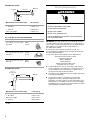
Electrical Shock Hazard
Plug into a grounded 3 prong outlet.
Do not remove ground prong.
Do not use an adapter.
Do not use an extension cord.
Failure to follow these instructions can result in death,
fire, or electrical shock.
WARNING

7
■ The grounded 3 prong outlet is to be located inside the
cabinet above the range hood at a maximum distance of
33⁷⁄₁₆" (85.0 cm) from where the power cord exits the hood.
See illustration.
INSTALLATION INSTRUCTIONS
Prepare Location
NOTE: For vented installations, it is recommended that the vent
system be installed before hood is installed.
Before making cutouts, make sure there is proper clearance
within the ceiling or wall for exhaust vent.
1. For vented installations, determine which venting method to
use: roof or wall.
2. Select a flat surface for assembling the range hood. Place
covering over that surface.
3. Using 2 or more people, lift the range hood and set it upside
down onto covered surface.
4. If cabinet has recessed bottom, add wood filler strips on each
side. Install screws to attach filler strips in locations shown.
Determine Wiring Hole Location
Cut only one 1¹⁄₄" (3.2 cm) diameter wiring access hole. See
Step 2 for wiring hole location instructions.
1. Determine and clearly mark a vertical centerline on the wall
and cabinet in the area the vent opening will be made.
2. To wire through top:
Mark a line distance “A” from the left of the centerline on the
underside of the cabinet. Mark the point on this line that is
2" (5.0 cm) from back wall. Drill a 1¼" (3.0 cm) diameter hole
through the cabinet at this point.
33⁷⁄₁₆" (85 cm)
GROUNDING INSTRUCTIONS
SAVE THESE INSTRUCTIONS
■
For a grounded, cord-connected range hood:
This range hood must be grounded. In the event of an
electrical short circuit, grounding reduces the risk of electric
shock by providing an escape wire for the electric current.
This range hood is equipped with a cord having a grounding
wire with a grounding plug. The plug must be plugged into
an outlet that is properly installed and grounded.
WARNING:
Improper grounding can result in a risk of
electric shock.
Consult a qualified electrician if the grounding instructions
are not completely understood, or if doubt exists as to
whether the range hood is properly grounded.
Do not use an extension cord. If the power supply cord is too
short, have a qualified electrician install an outlet near the
range hood.
WARNING
Excessive Weight Hazard
Use two or more people to move and install
range hood.
Failure to do so can result in back or other injury.
Cabinet
bottom
Wall
3" (7.6 cm)
Wood filler strips
(recessed cabinet
bottoms only)
3" (7.6 cm)
A. Centerline
A. 12" (30.5 cm) for 30" (76.2 cm) models
12¼" (31.1 cm) for 36" (91.4 cm) models
A
Centerline
2" (5.1 cm)
from wall,
not cabinet
frame
A

8
Style 1 - Cut Openings for 3¼" x 10" (8.3 cm x 25.4 cm)
Rectangular Vent System
Roof Venting
To make a 4¼" x 10½" (10.8 cm x 26.7 cm) rectangular cutout
on the underside of cabinet top and bottom:
1. Mark lines ½" (1.2 cm) and 4¾" (12.1 cm) from the back wall
on the centerline of the underside of cabinet.
2. Mark lines 5¼" (13.3 cm) to the right and left of the centerline
on the underside of cabinet.
3. Use saber or keyhole saw to cut a rectangular opening for
vent.
4. Repeat steps 1-3 for the underside of the top of the cabinet.
Wall Venting
To make a 3½" x 10½" (8.9 cm x 26.7 cm) rectangle in the
wall:
1. Make 2 lines by measuring ³⁄₈" (9.5 mm) and 3⁷⁄₈" (9.8 cm)
down from underside of cabinet and mark on the centerline
on the back wall.
2. Mark lines 5¼" (13.3 cm) to the right and left of the centerline
on the wall.
3. Use saber or keyhole saw to cut a rectangular opening in the
wall for the vent.
Style 2 - Cut Openings for 3¼" x 10" (8.3 x 25.4 cm)
Rectangular Vent to Round Vent Transition
Roof Venting
To make a 4¼" x 10½" (10.8 cm x 26.7 cm) rectangular cutout
on the underside of cabinet bottom:
1. Mark lines ½" (1.2 cm) and 4¾" (12.1 cm) from the back wall
on the centerline of the underside of cabinet.
2. Mark lines 5¼" (13.3 cm) to the right and left of the centerline
on the underside of cabinet.
3. Use saber or keyhole saw to cut a rectangular opening for
vent.
To make a circular vent opening on the underside of the
cabinet top:
1. Mark a centerline on the underside of the top of cabinet.
2. Mark a line 5" (12.7 cm) from the back wall on the underside
of the top of cabinet.
3. Use a compass or a circle template to draw a circle with a
diameter that is ¼" (0.64 cm) larger than the vent.
4. Use saber or keyhole saw to cut the circular vent opening.
Install Vent System
1. Install vent through the vent opening in upper cabinet or wall.
Complete venting system according to the selected venting
method. See “Venting Requirements” section.
2. Use caulking to seal exterior wall or roof opening around the
cap.
5¹/₄"
(13.3 cm)
5¹/₄"
(13.3 cm)
*4³⁄₄"
(12.1 cm)
*From wall, not cabinet frame
Cabinet cutouts
*¹⁄₂" (1.2 cm)
³⁄₈"
3 ⁷⁄₈"
Cabinet
front
5
¹⁄₄"
(0.9 cm)
(9.8 cm)
(13.3 cm)
Centerline
5¹/₄"
(13.3 cm)
5¹/₄"
(13.3 cm)
*4³⁄₄"
(12.1 cm)
*From wall, not cabinet frame
*¹⁄₂" (1.2 cm)
Circular vent opening
Cabinet
cutouts
*From wall, not
cabinet frame
*5"
(12.7 cm)

9
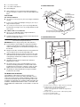
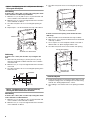
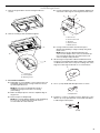
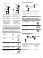
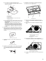
Install Range Hood
1. Remove the grease filters. See the “Range Hood Care”
section.
2. Remove mounting screws and lateral supports.
3. For vented installations:
■ Depending on your installation, remove either top or rear
rectangular vent knockout. If using round vent, remove
top rectangular knockout.
NOTE: Do not remove rectangular knockouts if
installation of range hood is to be non-venting
(recirculating).
■ Make sure damper pivot is nearest to top/back edge of
range hood.
■ Remove tape from damper flap.
NOTE: The exhaust adaptor/damper can be installed up
to 1" (2.5 cm) on either side of the hood center to
accommodate off-center ductwork.
■ If using rectangular vent, attach rectangular damper/vent
connectors to the range hood using sheet metal screws.
■ If using round vent, attach vent transition piece
(purchased separately) to range hood top using sheet
metal screws.
NOTE: If the wall cap is directly behind the vent
connector, the dampers in the connector and wall cap
must not interfere with each other. Remove the vent
connector damper if they interfere.
4. Lift the range hood up under cabinet and determine final
location by centering beneath cabinet. Mark on the underside
of cabinet the location of the 4 keyhole mounting slots on the
range hood. Set range hood aside on a covered surface.
5. Use ¹⁄₈" (3 mm) drill bit and drill 4 pilot holes as shown.
6. Install the 4 - #10 x ⁵⁄₈" mounting screws in pilot holes. Leave
about ¹⁄₄" (6.4 cm) space between screw heads and cabinet
to slide range hood into place.
A. Lateral supports
B. Mounting screws
A
A
B
A. Vertical vent
B. Sheet metal screws
C. Hinge pin
D. Vent knockouts
E. Horizontal vent
A. Keyhole slot
A. Drill pilot hole
A
B
C
D
C
B
E
A
A
¹⁄₄"
(6.4 mm)

10
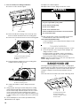
7. For non-vented (recirculating) installations:
■ Remove screws and rear support.
■ Remove the blower mounting screws. Push up on the
blower to detach the blower from the mounting plate.
■ Remove the vent knockout from the front mounting plate.
■ Rotate the blower and attach to front mounting plate.
Install the blower mounting screws.
■ Install charcoal filters. See the “Range Hood Care”
section.
8. Using 2 people, lift range hood into final position, feeding
electrical wire through wiring opening. Position the range
hood so that the large end of the keyhole slots are over the
screws. Then push the hood toward the wall so that the
screws are in the neck of the slots. Tighten mounting screws
to cabinet, making sure mounting screws are in narrow neck
of slots.
9. Check that damper, if used, rotates up and down freely.
10. Reinstall the rear support.
11. Replace the 2 lateral supports.
12. Replace filters. See the “Range Hood Care” section.
13. Plug 3-prong power cord into a grounded 3-prong outlet
located inside the cabinet above the range hood.
14. For Vented Installations Only:
Connect ventwork to hood. Seal joints with clamps to make
secure and airtight.
Complete Installation
1. Replace grease filters. See the “Range Hood Care” section.
2. Check the operation of the range hood fan and light. See
“Range Hood Use” section.
If range hood does not operate, check to see whether a
circuit breaker has tripped or a household fuse has blown.
Disconnect power and check wiring connections.
NOTE: To get the most efficient use from your new range hood,
read the “Range Hood Use” section.
RANGE HOOD USE
The range hood is designed to remove smoke, cooking vapors
and odors from the cooktop area. For best results, start the hood
before cooking and allow it to operate several minutes after the
cooking is complete to clear all smoke and odors from the
kitchen.
The hood controls are located on the center of the range hood.
A. Rear support
A. Front mounting plate knockout
B. Blower mounting screws
C. Blower
A. Front mounting plate
B. Blower mounting screws
A
A
B
C
A
B
A. Halogen lamp housings
B. Grease filter handle
C. Blower and light controls
D. Grease filter
Electrical Shock Hazard
Plug into a grounded 3 prong outlet.
Do not remove ground prong.
Do not use an adapter.
Do not use an extension cord.
Failure to follow these instructions can result in death,
fire, or electrical shock.
WARNING
A
B
C
D

11
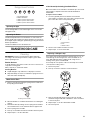
Range Hood Controls
Operating the light
The On/Off light button controls both lights. Press once for On
and again for Off.
Operating the blower
The Blower Speed buttons turn the blower on and control the
blower speed and sound level for quiet operation. The speed can
be changed anytime during fan operation by pressing the desired
blower speed button.
The Blower Off button turns the blower Off.
RANGE HOOD CARE
Cleaning
IMPORTANT: Clean the hood and grease filters frequently
according to the following instructions. Replace grease filters
before operating hood.
Exterior Surfaces:
To avoid damage to the exterior surface, do not use steel wool or
soap-filled scouring pads.
Always wipe dry to avoid water marks.
Cleaning Method:
■ Liquid detergent soap and water, or all-purpose cleanser
■ Wipe with damp soft cloth or nonabrasive sponge, then rinse
with clean water and wipe dry.
Metal Grease Filter:
1. Remove each filter by pulling the spring release handle and
then pulling down the filter.
2. Wash metal filters as needed in dishwasher or hot detergent
solution.
3. Reinstall the filter by making sure the spring release handles
are toward the front. Insert aluminum filter into upper track.
4. Push in spring release handle.
5. Push up on metal filter and release handle to latch into place.
6. Repeat steps 1-5 for the other filter.
Non-Vented (recirculating) Installation Filters:
The charcoal filter is not washable. It should last up to six months
with normal use. Replace with Charcoal Filter Kit Number
W10272068.
To replace charcoal filter:
1. Cover the grill that protects the blower motor with the
charcoal filter so that the slots on the filter correspond to the
pins on the sides of the motor protection grill.
2. Turn the charcoal filter clockwise to lock it.
3. Repeat steps 1-2 on the other filter.
Replacing a Halogen Lamp
Turn off the range hood and allow the halogen lamp to cool. To
avoid damage or decreasing the life of the new bulb, do not
touch bulb with bare fingers. Replace bulb, using tissue or
wearing cotton gloves to handle bulb.
If new lamps do not operate, make sure the lamps are inserted
correctly before calling service.
1. Disconnect power.
2. Push up on the lens and turn it counterclockwise.
3. Remove the bulb and replace it with a 120-volt, 50-watt
maximum halogen bulb with a GU10 base. Turn it clockwise
to lock it into place.
4. Repeat steps 2-3 for the other bulb if needed.
5. Reconnect power.
A. On/Off light button
B. Blower Off button
C. Blower speed minimum button
D. Blower speed medium button
E. Blower speed maximum button
A. Spring release handle
A
B
C
D
E
A
A. Charcoal filter
B. Pins
C. Blower motor
A
B
C

12
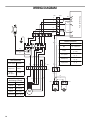
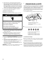
WIRING DIAGRAM
M
1
23
4
5
6
7
8
9
W
R
BK
GY
BR
Y
Power cord
BK
R
W
Y
BR
1
23
4
5
6
7
8
9
1
23
4
5
6
2
1
RED
W
BK
BU
Y/G
Y
CON 1
CON 2
CON 5
CO
N 8
CON 6
CO
N 7
R
BU
GY
CON 9
CON 10
Y/G
Y/G
Y/G
W
BK
W
BK
GY
GY
Push button board
Switch operation
Position
Connection
Off
No connection
Lamps
Low speed
Med speed
High speed
GY/Y
(L - LA)
GY/W
(L - 1)
GY/R
(L - 2)
GY/BK
(L - 3)
BU
Y
BU
Y
W
BK
BK
W
BU
Y
BU
BU
Capacitor
Varisitor
W
R
BK
GY
BU
Motor
characteristics
Power supply
Frequency
Power
absorption
120 VAC
60 Hz
240 W
Motor
resistance (Ohms)
BU-R
BU-GY
BU-BK
BU-W
Room
temperature
37.7
30.3
28.8 (max)
45.1 (min)
73.4˚F (23˚C)
CON3
CON 4

13
ASSISTANCE OR SERVICE
When calling for assistance or service, please know the purchase
date and the complete model and serial number of your
appliance. This information will help us to better respond to your
request.
If you need replacement parts
If you need to order replacement parts, we recommend that you
use only factory specified parts. Factory specified parts will fit
right and work right because they are made with the same
precision used to build every new appliance. To locate factory
specified replacement parts in your area, call us or your nearest
designated service center.
In the U.S.A.
Call the Whirlpool Customer eXperience Center
toll free: 1-800-253-1301.
Our consultants provide assistance with:
■ Features and specifications on our full line of appliances.
■ Installation information.
■ Use and maintenance procedures.
■ Accessory and repair parts sales.
■ Specialized customer assistance (Spanish speaking, hearing
impaired, limited vision, etc.).
■ Referrals to local dealers, repair parts distributors and service
companies. Whirlpool designated service technicians are
trained to fulfill the product warranty and provide after-
warranty service, anywhere in the United States.
To locate the Whirlpool designated service company in your
area, you can also look in your telephone directory Yellow
Pages.
For further assistance
If you need further assistance, you can write to Whirlpool
Corporation with any questions or concerns at:
Whirlpool Brand Home Appliances
Customer eXperience Center
553 Benson Road
Benton Harbor, MI 49022-2692
Please include a daytime phone number in your correspondence.
In Canada
Call the Whirlpool Canada LP Customer eXperience Centre toll
free: 1-800-807-6777.
Our consultants provide assistance with:
■ Features and specifications on our full line of appliances.
■ Use and maintenance procedures.
■ Accessory and repair parts sales.
■ Referrals to local dealers, repair parts distributors, and
service companies. Whirlpool Canada LP designated service
technicians are trained to fulfill the product warranty and
provide after-warranty service, anywhere in Canada.
For further assistance
If you need further assistance, you can write to Whirlpool
Canada LP with any questions or concerns at:
Customer eXperience Centre
Whirlpool Canada LP
200 - 6750 Century Ave.
Mississauga, Ontario L5N 0B7
Please include a daytime phone number in your correspondence.
Accessories
Replacement Charcoal Filter Kit (2 Pack of Filters)
(for non-vented installations only)
Order Part Number W10272068

14
WHIRLPOOL CORPORATION MAJOR APPLIANCE WARRANTY
LIMITED WARRANTY
For one year from the date of purchase, when this major appliance is operated and maintained according to instructions attached to or
furnished with the product, Whirlpool Corporation or Whirlpool Canada LP (hereafter “Whirlpool”) will pay for Factory Specified Parts
and repair labor to correct defects in materials or workmanship. Service must be provided by a Whirlpool designated service company.
This limited warranty is valid only in the United States or Canada and applies only when the major appliance is used in the country in
which it was purchased. Outside the 50 United States and Canada, this limited warranty does not apply. Proof of original purchase date
is required to obtain service under this limited warranty.
ITEMS EXCLUDED FROM WARRANTY
This limited warranty does not cover:
1. Service calls to correct the installation of your major appliance, to instruct you on how to use your major appliance, to replace or
repair house fuses, or to correct house wiring or plumbing.
2. Service calls to repair or replace appliance light bulbs, air filters or water filters. Consumable parts are excluded from warranty
coverage.
3. Repairs when your major appliance is used for other than normal, single-family household use or when it is used in a manner that is
contrary to published user or operator instructions and/or installation instructions.
4. Damage resulting from accident, alteration, misuse, abuse, fire, flood, acts of God, improper installation, installation not in
accordance with electrical or plumbing codes, or use of consumables or cleaning products not approved by Whirlpool.
5. Cosmetic damage, including scratches, dents, chips or other damage to the finish of your major appliance, unless such damage
results from defects in materials or workmanship and is reported to Whirlpool within 30 days from the date of purchase.
6. Any food loss due to refrigerator or freezer product failures.
7. Costs associated with the removal from your home of your major appliance for repairs. This major appliance is designed to be
repaired in the home and only in-home service is covered by this warranty.
8. Repairs to parts or systems resulting from unauthorized modifications made to the appliance.
9. Expenses for travel and transportation for product service if your major appliance is located in a remote area where service by an
authorized Whirlpool servicer is not available.
10. The removal and reinstallation of your major appliance if it is installed in an inaccessible location or is not installed in accordance
with published installation instructions.
11. Major appliances with original model/serial numbers that have been removed, altered or cannot be easily determined. This warranty
is void if the factory applied serial number has been altered or removed from your major appliance.
The cost of repair or replacement under these excluded circumstances shall be borne by the customer.
DISCLAIMER OF IMPLIED WARRANTIES; LIMITATION OF REMEDIES
CUSTOMER'S SOLE AND EXCLUSIVE REMEDY UNDER THIS LIMITED WARRANTY SHALL BE PRODUCT REPAIR AS PROVIDED
HEREIN. IMPLIED WARRANTIES, INCLUDING WARRANTIES OF MERCHANTABILITY OR FITNESS FOR A PARTICULAR PURPOSE,
ARE LIMITED TO ONE YEAR OR THE SHORTEST PERIOD ALLOWED BY LAW. WHIRLPOOL SHALL NOT BE LIABLE FOR
INCIDENTAL OR CONSEQUENTIAL DAMAGES. SOME STATES AND PROVINCES DO NOT ALLOW THE EXCLUSION OR LIMITATION
OF INCIDENTAL OR CONSEQUENTIAL DAMAGES, OR LIMITATIONS ON THE DURATION OF IMPLIED WARRANTIES OF
MERCHANTABILITY OR FITNESS, SO THESE EXCLUSIONS OR LIMITATIONS MAY NOT APPLY TO YOU. THIS WARRANTY GIVES
YOU SPECIFIC LEGAL RIGHTS, AND YOU MAY ALSO HAVE OTHER RIGHTS WHICH VARY FROM STATE TO STATE OR PROVINCE
TO PROVINCE.
If outside the 50 United States and Canada, contact your authorized Whirlpool dealer to determine if another warranty applies.
If you need service, first see the “Troubleshooting” section of the Use & Care Guide. After checking “Troubleshooting,” you may find
additional help by checking the “Assistance or Service” section or by calling Whirlpool. In the U.S.A., call 1-800-253-1301. In Canada,
call 1-800-807-6777. 9/07
Keep this book and your sales slip together for future
reference. You must provide proof of purchase or installation
date for in-warranty service.
Write down the following information about your major appliance
to better help you obtain assistance or service if you ever need it.
You will need to know your complete model number and serial
number. You can find this information on the model and serial
number label located on the product.
Dealer name____________________________________________________
Address ________________________________________________________
Phone number__________________________________________________
Model number __________________________________________________
Serial number __________________________________________________
Purchase date __________________________________________________

15
SÉCURITÉ DE LA HOTTE DE CUISINIÈRE
Risque possible de décès ou de blessure grave si vous ne
suivez pas immédiatement les instructions.
Risque possible de décès ou de blessure grave si vous
ne suivez pas les instructions.
Tous les messages de sécurité vous diront quel est le danger potentiel et vous disent comment réduire le risque de blessure et
ce qui peut se produire en cas de non-respect des instructions.
Votre sécurité et celle des autres est très importante.
Nous donnons de nombreux messages de sécurité importants dans ce manuel et sur votre appareil ménager. Assurez-vous de
toujours lire tous les messages de sécurité et de vous y conformer.
AVERTISSEMENT
DANGER
Voici le symbole d’alerte de sécurité.
Ce symbole d’alerte de sécurité vous signale les dangers potentiels de décès et de blessures graves à vous
et à d’autres.
Tous les messages de sécurité suivront le symbole d’alerte de sécurité et le mot “DANGER” ou
“AVERTISSEMENT”. Ces mots signifient :

16
IMPORTANTES INSTRUCTIONS DE SÉCURITÉ
LIRE ET CONSERVER CES INSTRUCTIONS
AVERTISSEMENT : POUR RÉDUIRE LE RISQUE
D'INCENDIE, CHOC ÉLECTRIQUE OU DOMMAGES
CORPORELS, RESPECTER LES INSTRUCTIONS
SUIVANTES :
■ Utiliser cet appareil uniquement dans les applications
envisagées par le fabricant. Pour toute question, contacter
le fabricant.
■ Avant d'entreprendre un travail d'entretien ou de nettoyage,
interrompre l'alimentation de la hotte au niveau du tableau
de disjoncteurs, et verrouiller le tableau de disjoncteurs
pour empêcher tout rétablissement accidentel de
l'alimentation du circuit. Lorsqu'il n'est pas possible de
verrouiller le tableau de disjoncteurs, placer sur le tableau
de disjoncteurs une étiquette d'avertissement proéminente
interdisant le rétablissement de l'alimentation.
■ Tout travail d'installation ou câblage électrique doit être
réalisé par une personne qualifiée, dans le respect des
prescriptions de tous les codes et normes applicables, y
compris les codes du bâtiment et de protection contre les
incendies.
■ Ne pas faire fonctionner un ventilateur dont le cordon ou la
fiche est endommagé(e). Jeter le ventilateur ou le retourner
à un centre de service agréé pour examen et/ou réparation.
■ Une source d'air de débit suffisant est nécessaire pour le
fonctionnement correct de tout appareil à gaz (combustion
et évacuation des gaz à combustion par la cheminée), pour
qu'il n'y ait pas de reflux des gaz de combustion. Respecter
les directives du fabricant de l'équipement de chauffage et
les prescriptions des normes de sécurité - comme celles
publiées par la National Fire Protection Association (NFPA)
et l'American Society for Heating, Refrigeration and Air
Conditioning Engineers (ASHRAE), et les prescriptions des
autorités réglementaires locales.
■ Lors d'opérations de découpage et de perçage dans un mur
ou un plafond, veiller à ne pas endommager les câblages
électriques ou canalisations qui peuvent s'y trouver.
■ Les ventilateurs d'évacuation doivent toujours décharger
l'air à l'extérieur.
MISE EN GARDE : Cet appareil est conçu uniquement
pour la ventilation générale. Ne pas l'utiliser pour l'extraction
de matières ou vapeurs dangereuses ou explosives.
MISE EN GARDE : Pour minimiser le risque d'incendie
et évacuer adéquatement les gaz, veiller à acheminer l'air
aspiré par un conduit jusqu'à l'extérieur - ne pas décharger
l'air aspiré dans un espace vide du bâtiment comme une
cavité murale, un plafond, un grenier, un vide sanitaire ou
un garage.
AVERTISSEMENT : POUR RÉDUIRE LE RISQUE
D'INCENDIE, UTILISER UNIQUEMENT DES CONDUITS
MÉTALLIQUES.
AVERTISSEMENT : POUR MINIMISER LE RISQUE
D'UN FEU DE GRAISSE SUR LA CUISINIÈRE :
■ Ne jamais laisser un élément de surface fonctionner à
puissance de chauffage maximale sans surveillance. Un
renversement/débordement de matière graisseuse pourrait
provoquer une inflammation et la génération de fumée.
Utiliser une puissance de chauffage moyenne ou basse
pour le chauffage d'huile.
■ Veiller à toujours faire fonctionner le ventilateur de la hotte
lors de la cuisson avec une puissance de chauffage élevée
ou lors de la cuisson d'un mets à flamber (à savoir crêpes
Suzette, cerise jubilée, steak au poivre flambé).
■ Nettoyer fréquemment les ventilateurs d'extraction. Veiller à
ne pas laisser la graisse s'accumuler sur les surfaces du
ventilateur ou des filtres.
■ Utiliser toujours un ustensile de taille appropriée. Utiliser
toujours un ustensile adapté à la taille de l'élément
chauffant.
AVERTISSEMENT : POUR RÉDUIRE LE RISQUE DE
DOMMAGES CORPORELS APRÈS LE DÉCLENCHEMENT
D'UN FEU DE GRAISSE SUR LA CUISINIÈRE, APPLIQUER
LES RECOMMANDATIONS SUIVANTES :
a
■ Placer sur le récipient un couvercle bien ajusté, une tôle à
biscuits ou un plateau métallique POUR ÉTOUFFER LES
FLAMMES, puis éteindre le brûleur. VEILLER À ÉVITER
LES BRÛLURES. Si les flammes ne s'éteignent pas
immédiatement, ÉVACUER LA PIÈCE ET APPELER LES
POMPIERS.
■ NE JAMAIS PRENDRE EN MAIN UN RÉCIPIENT
ENFLAMMÉ - vous risquez de vous brûler.
■ NE PAS UTILISER D'EAU, ni un torchon humide - ceci
pourrait provoquer une explosion de vapeur brûlante.
■ Utiliser un extincteur SEULEMENT si :
– Il s'agit d'un extincteur de classe ABC, dont on connaît le
fonctionnement.
– Il s'agit d'un petit feu encore limité à l'endroit où il s'est
déclaré.
– Les pompiers ont été contactés.
– Il est possible de garder le dos orienté vers une sortie
pendant l'opération de lutte contre le feu.
a
Recommandations tirées des conseils de sécurité en cas
d'incendie de cuisine publiés par la NFPA.
■ AVERTISSEMENT : Pour réduire le risque d'incendie
ou de choc électrique, ne pas utiliser ce ventilateur avec un
quelconque dispositif de réglage de la vitesse à semi-
conducteurs.

17
EXIGENCES D'INSTALLATION
Outils et pièces
Rassembler les outils et composants nécessaires avant
d’entreprendre l’installation. Lire et observer les instructions
fournies avec chacun des outils de la liste ci-dessous.
Outils nécessaires
■ Perceuse
■ 1 foret de 1 ¹⁄₄" (3 cm)
■ Foret de ¹⁄₈" (3 mm) pour avant-trous
■ Crayon
■ Pince à dénuder ou couteau utilitaire
■ Mètre-ruban ou règle
■ Pistolet à calfeutrage et composé de calfeutrage résistant
aux intempéries
■ Tournevis à lame plate
■ Tournevis Phillips
Pour une installation avec décharge à l’extérieur, vous aurez
également besoin de :
■ Scie sauteuse ou scie à guichet
■ Brides de conduit
■ Cisaille de ferblantier
■ Compas ou gabarit de diamètre 8" (20,3 cm)
Pièces fournies
Retirer les pièces de l'emballage. Vérifier que toutes les pièces
sont présentes.
■ 2 - filtres métalliques
■ 6 - vis de montage de 4,5 x 13 mm
■ 3 - vis de clapet de 4 x 8 mm
■ Module clapet/connecteur de conduit de 3¼" x 10"
(8,3 x 25,4 cm)
■ 4 - vis de 5 x 45 mm
■ 4 - vis d’ancrage mural de 8 x 40 mm
■ Ensemble de recyclage
■ Filtres à charbon - Installation sans décharge à l’extérieur
(recyclage). Pour commander des filtres à charbon de
rechange, voir la section “Assistance ou service”.
Pièces nécessaires
Installations avec décharge à l'extérieur :
■ Conduit métallique rond de 3¹⁄₄" x 10" (8,3 x 25,4 cm) ou d'un
diamètre de 6" (15,2 cm) ou plus
■ Clapet anti-reflux de 6" (15,2 cm) ou plus de diamètre, pour
utilisation avec un circuit d'évacuation de 6" (15,2 cm) ou
plus de diamètre
■ Raccord de transition de 3¹⁄₄" x 10" (8,3 x 25,4 cm) sur
6" (15,2 cm) ou plus de diamètre pour utilisation avec circuit
d'évacuation d'un diamètre de 6" (15,2 cm) ou plus.
Pour placards avec cavité au fond :
■ Deux tringles d’appui de largeur 2" (5,1 cm). Longueur et
épaisseur selon les dimensions de l'encastrement.
■ Quatre vis à bois à tête plate ou vis à métaux avec rondelles
et écrous, pour la fixation des tringles d’appui.
Exigences d'emplacement
IMPORTANT : Observer les dispositions de tous les codes et
règlements en vigueur.
■ C'est à l'installateur qu'incombe la responsabilité de
respecter les distances de séparation exigées, spécifiées sur
la plaque signalétique de l'appareil. La plaque signalétique
est située à l'intérieur de la hotte, sur la paroi gauche.
■ Installer la hotte de cuisinière à distance de toute zone
exposée à des courants d'air, comme fenêtres, portes et
bouches de chauffage.
■ Respecter les dimensions indiquées pour les ouvertures à
découper dans les placards; ces dimensions tiennent compte
des valeurs minimales des dégagements de séparation.
Avant d'effectuer des découpages, consulter les instructions
d'installation fournies par le fabricant de la table de cuisson/
cuisinière.
■ On doit disposer d'une prise de courant électrique reliée à la
terre. Voir la section “Spécifications électriques”.
■ La hotte a été configurée à l'usine pour une installation avec
décharge à l'extérieur. Pour une installation sans décharge à
l'extérieur (recyclage), l'ensemble de recyclage est inclus.
Voir la section “Assistance ou service” pour commander un
filtre à charbon de rechange (pièce n° W10272068).
■ Assurer l'étanchéité au niveau de chaque ouverture
découpée dans le plafond ou le mur pour l'installation de la
hotte de cuisinière.
Installation dans une résidence mobile
L'installation de cette hotte de cuisinière doit satisfaire aux
exigences de la norme Manufactured Home Construction Safety
Standards, Titre 24 CFR, partie 328 (anciennement Federal
Standard for Mobile Home Construction and Safety, titre 24, HUD,
partie 280); lorsque cette norme n'est pas applicable, l'installation
doit satisfaire aux critères de la plus récente édition de la norme
Manufactured Home Installation 1982 (Manufactured Home Sites,
Communities and Setups) ANSI A225.1/NFPA 501A*, ou des
codes et règlements locaux.
Dimensions du produit
29 ⁷⁄₈" (75,9 cm) - Modèle 30" (76,2 cm)
35 ⁷⁄₈" (91,1 cm) - Modèle 36" (91,4 cm)
1³⁄₁₆"
(3,0 cm)
2"
(5,1 cm)
12"
(30,5 cm)
7¹⁄₄"
(18,4 cm)
9"
(22,9 cm)
⁵⁄₈"
(1,6 cm)
⁵⁄₈"
(1,6 cm)
19
³⁄₄
"
(50,2 cm)
3" (7,6 cm) -
Modèle 30" (76,2 cm)
5 ³⁄₄" (14,6 cm) -
Modèle 36" (91,4 cm)

18
Dégagements de séparation à respecter
Exigences concernant l'évacuation
(Uniquement pour modèles avec évacuation)
■ Le système d'évacuation doit décharger l'air à l'extérieur,
excepté pour les installations sans décharge à l'extérieur
(recyclage).
■ Ne pas terminer le conduit d'évacuation dans un grenier ou
dans un autre espace fermé.
■ Ne pas utiliser une bouche de décharge murale de
4" (10,2 cm) normalement utilisée pour un équipement
de buanderie.
■ Utiliser un conduit métallique rond de 6" (15,2 cm) ou plus de
diamètre, ou un conduit métallique rectangulaire de 3¼" x
10" (8,3 cm x 25,4 cm). Un conduit en métal rigide est
recommandé. L'utilisation d'un conduit de plastique ou en
feuille métallique est déconseillée.
■ La longueur du système d'évacuation et le nombre de coudes
doit être réduit au minimum pour fournir la meilleure
performance.
Pour un fonctionnement efficace et silencieux :
■ Ne pas utiliser plus de trois coudes à 90°.
■ Veiller à ce qu'il y ait une section droite de conduit de
24" (61,0 cm) au minimum entre deux coudes, si on doit
utiliser plus de un raccord coudé.
■ Ne pas installer 2 coudes ensemble.
■ Au niveau de chaque jointure du conduit de décharge,
assurer l'étanchéité avec les brides de serrage pour conduit.
■ Le système d'évacuation doit comporter un clapet. Si la
bouche de décharge murale ou par le toit comporte un
clapet, ne pas utiliser le clapet fourni avec la hotte de
cuisinière.
■ Autour de la bouche de décharge à l'extérieur par un mur ou
par le toit, assurer l'étanchéité avec un produit de
calfeutrage.
Installations pour régions à climat froid
On doit installer un clapet anti-reflux additionnel à l'arrière pour
minimiser le reflux d'air froid, et incorporer un élément d'isolation
thermique pour minimiser la conduction de chaleur par
l'intermédiaire du conduit d'évacuation, de l'intérieur de la
maison à l'extérieur. Le clapet anti-reflux doit être placé du côté
air froid par rapport à l'élément d'isolation thermique.
L'élément d'isolation thermique doit être aussi proche que
possible de l'endroit où le système d'évacuation s'introduit dans
la partie chauffée de la maison.
Air d'appoint
Le code du bâtiment local peut exiger l'emploi d'un système
d'appoint d'air lors de l'emploi d'un ventilateur d'extraction dont
la capacité d'aspiration est supérieure à un débit (pieds cubes
par minute) spécifié. Le débit spécifié, pieds cubes par minute,
est variable d'une juridiction à une autre. Consulter un
professionnel des installations de chauffage ventilation/
climatisation au sujet des exigences spécifiques applicables
dans la juridiction locale.
Méthodes d'évacuation
La sortie à l'extérieur du circuit d'évacuation peut se faire à
travers le toit ou à travers un mur. Utiliser un conduit
rectangulaire de 3¼" x 10" (8,3 cm x 25,4 cm) pour une longueur
effective maximale de circuit de 35 pi (10,7 cm) ou un conduit
rond de 6" (15,2 cm) ou plus de diamètre pour une longueur
effective maximale de circuit de 50 pi (15,2 m).
REMARQUE : On déconseille l'emploi d'un conduit flexible. Un
conduit flexible peut susciter une rétro-pression et des
turbulences de l'air, ce qui réduit considérablement la
performance.
A. Dégagement min. de 18" (45,7 cm) entre le placard supérieur et le plan
de travail
B. Distance maximale suggérée du bas de la hotte à la surface de cuisson
24" (61 cm) min. pour surfaces de cuisson électriques
27" (68,6 cm) min. pour surfaces de cuisson au gaz
30" (76,2 cm) max. suggéré
C. Largeur minimale de l'ouverture du placard de 30" (76,2 cm) ou
36" (91,4 cm)
D. Profondeur de placard 13" (33 cm)
E. Hauteur de placard du bas 36" (91,4 cm)
A
B
C
D
E

19
Calcul de la longueur effective du circuit d'évacuation
Pour calculer la longueur effective du circuit d'évacuation
nécessaire, additionner les longueurs équivalentes (pieds/mètres)
de tous les composants utilisés dans le système.
Système de décharge circulaire de 6" (15,2 cm) ou plus
Exemple de système de décharge
Système de décharge de 3¹⁄₄" x 10" (8,3 cm x 25,4 cm)
Exemple de système de décharge
Décharge à travers le toit Décharge à travers le mur
A. Conduit rond de diamètre
6" (15,2 cm) ou plus ou conduit
rectangulaire de 3¼" x 10"
(8,3 x 25,4 cm) à travers le toit
B. Conduit rond : utiliser un clapet
rond de 6" (15,2 cm) ou plus de
diamètre (achat séparé)
C. Conduit rond : Utiliser un
raccord de transition de 3¼" x
10" (8,3 x 25,4 cm) sur 6"
(15,2 cm) ou de plus grande
taille (achat séparé).
D. 24" (61 cm) - 30" (76,2 cm)
au-dessus de la surface de
cuisson électrique
27" (68,6 cm) - 30" (76,2 cm)
au-dessus de la surface de
cuisson au gaz
E. Bouche de décharge sur toit
A. Conduit de diamètre 6"
(15,2 cm) ou plus ou conduit
rectangulaire de 3¼" x 10" (8,3
x 25,4 cm) à travers le toit
B. Conduit rond : Utiliser un
raccord de transition de 3¼" x
10" (8,3 x 25,4 cm) sur 6"
(15,2 cm) ou de plus grande
taille
C. Sortie à travers le mur pour
conduit rectangulaire de 3¼" x
10" (8,3 x 25,4 cm)
D. 24" (61 cm) - 30" (76,2 cm)
au-dessus de la surface de
cuisson électrique
27" (68,6 cm) - 30" (76,2 cm)
au-dessus de la surface de
cuisson au gaz
E. Bouche de décharge murale
Composant Conduit rond
Coude à 45° 2,5 pi
(0,8 m)
Coude à 90° 5 pi
(1,5 m)
Bouche de décharge murale
de 6" (15,2 cm) ou plus
0 pi
(0 m)
3¹⁄₄" x 10" (8,3 cm x 25,4 cm)
sur 6" (15,2 cm) ou plus
4,5 pi
(1,4 m)
Coude à 90° de 3¹⁄₄" x 10"
(8,3 cm x 25,4 cm)
sur 6" (15,2 cm) ou plus
5 pi
(1,5 m)
A
B
D
C
E
A
B
C
D
E
Longueur maximale recommandée = 50 pi (15,2 m)
1 - coude à 90° = 5 pi (1,5 m)
1 - bouche de décharge murale = 0 pi (0 m)
section droite de 8 pi (2,4 m) = 8 pi (2,4 m)
Longueur du système de dia.
7" (17,8 cm)
= 13 pi (3,9 m)
Composant
Coude à 90° de 3¹⁄₄" x 10"
(8,3 cm x 25,4 cm)
5 pi (1,5 m)
Coude plat de 3¹⁄₄" x 10"
(8,3 cm x 25,4 cm)
12 pi
(3,7 m)
Bouche de décharge murale
de 3¹⁄₄" x 10" (8,3 cm x
25,4 cm)
0 pi
(0 m)
Longueur maximale recommandée = 35 pi (10,7 m)
1 - coude à 90° = 5 pi (1,5 m)
section droite de 8 pi (2,4 m) = 8 pi (2,4 m)
1 - bouche de décharge murale = 0 pi (0 m)
Longueur du système de 3¹⁄₄" x 10"
(8,3 cm x 25,4 cm)
= 13 pi (3,9 m)
Bouche de
décharge murale
coude à 90˚
2 pi (0,6 m)
6 pi (1,8 m)
Bouche de
décharge murale
Coude de 3 ¹⁄₄" x 10"
(8,3 x 25,4 cm)
2 pi (0,6 m)
6 pi (1,8 m)

20
Spécifications électriques
IMPORTANT : La hotte doit être correctement reliée à la terre en
conformité avec les codes et règlements locaux en vigueur, ou en
l'absence de tels codes, avec le National Electrical Code, ANSI/
NFPA 70 (dernière édition) ou le Code canadien des installations
électriques, CSA C22.1. No. 0-M91 (dernière édition).
Si les codes le permettent et si on utilise un conducteur distinct
de liaison à la terre, il est recommandé qu’un électricien qualifié
vérifie la qualité de la liaison à la terre.
Pour obtenir un exemplaire des normes des codes ci-dessus,
contacter :
National Fire Protection Association
One Batterymarch Park
Quincy, MA 02269
CSA International
8501 East Pleasant Valley Road
Cleveland, Ohio 44131-5575
■ Une alimentation de 120 volts, 60 Hz, CA seulement, de
15 ou 20 ampères, protégée par un fusible est requise. On
recommande également d’utiliser un fusible ou un disjoncteur
temporisé. Il est recommandé de raccorder la hotte sur un
circuit distinct exclusif à cet appareil.
■ Cette hotte est équipée d’un cordon d’alimentation électrique
de liaison à la terre à trois broches.
■ Pour minimiser les risques de choc électrique, on doit
brancher le cordon sur une prise de courant de configuration
correspondante, à 3 alvéoles, reliée à la terre et installée
conformément aux codes et règlements locaux. Si une prise
de courant de configuration correspondante n’est pas
disponible, le client a la responsabilité et l’obligation de faire
installer par un électricien qualifié une prise de courant
correctement reliée à la terre.
■ La prise à 3 broches reliée à la terre doit se trouver dans un
placard situé au-dessus de la hotte, à une distance maximale
de 33⁷⁄₁₆" (85,0 cm) à partir du point duquel le cordon
d'alimentation sort de la hotte. Voir l’illustration.
AVERTISSEMENT
Risque de choc électrique
Brancher sur une prise à 3 alvéoles reliée à la terre.
Ne pas enlever la broche de liaison à la terre.
Ne pas utiliser un adaptateur.
Ne pas utiliser un câble de rallonge.
Le non-respect de ces instructions peut causer
un décès, un incendie ou un choc électrique.
33⁷⁄₁₆" (85 cm)
INSTRUCTIONS DE MISE À LA TERRE
CONSERVEZ CES INSTRUCTIONS
■
Pour une hotte reliée à la terre et connectée par un
cordon :
Cette hotte doit être reliée à la terre. Au cas où un court-
circuit se produirait, la liaison à la terre réduit le risque de
choc électrique, en permettant au courant de s'échapper
directement vers la terre. La hotte est équipée d'un cordon
comportant un conducteur de liaison à la terre avec fiche de
liaison à la terre. La fiche doit être branchée dans une prise
correctement installée et reliée à la terre.
AVERTISSEMENT :
Une mise à la terre incorrecte
peut entraîner un risque de choc électrique.
Consulter un électricien qualifié si les instructions de mise à
la terre ne sont pas complètement comprises, ou si vous
avez des doutes quant à la qualité de la liaison à la terre de
la hotte.
Ne pas utiliser de câble de rallonge. Si le cordon
d'alimentation électrique est trop court, faire installer une
prise près de la hotte par un électricien qualifié.
Page is loading ...
Page is loading ...
Page is loading ...
Page is loading ...
Page is loading ...
Page is loading ...
Page is loading ...
Page is loading ...
-
 1
1
-
 2
2
-
 3
3
-
 4
4
-
 5
5
-
 6
6
-
 7
7
-
 8
8
-
 9
9
-
 10
10
-
 11
11
-
 12
12
-
 13
13
-
 14
14
-
 15
15
-
 16
16
-
 17
17
-
 18
18
-
 19
19
-
 20
20
-
 21
21
-
 22
22
-
 23
23
-
 24
24
-
 25
25
-
 26
26
-
 27
27
-
 28
28


Bauknecht LI3VQA Owner's manual
- Category
- Cooker hoods
- Type
- Owner's manual
Ask a question and I''ll find the answer in the document
Finding information in a document is now easier with AI
in other languages
Related papers
Other documents
-
Maytag UXT5536AA User manual
-
Maytag 99043751D User manual
-
-
Whirlpool GXU7130DXQ Owner's manual
-
-
-
-
-
Amana LI3Z3A User guide
-
Whirlpool WVU7130JS User manual