Peavey JSX 212 User manual
- Category
- Musical Instrument Amplifier
- Type
- User manual
This manual is also suitable for

JSX 212
For information on other great Peavey products, visit your local Peavey dealer or visit us online at www.peavey.com
™
Joe Satriani Signature All-Tube Amplifier
Page is loading ...

3
IMPORTANT SAFETY INSTRUCTIONS
WARNING: When using electrical products, basic cautions should always be followed, including the following:
1. Read these instructions.
2. Keep these instructions.
3. Heed all warnings.
4. Follow all instructions.
5. Do not use this apparatus near water.
6. Clean only with a dry cloth.
7. Do not block any of the ventilation openings. Install in accordance with manufacturer’s instructions.
8. Do not install near any heat sources such as radiators, heat registers, stoves or other apparatus (including amplifiers)
that produce heat.
9. Do not defeat the safety purpose of the polarized or grounding-type plug. A polarized plug has two blades with one
wider than the other. A grounding type plug has two blades and a third grounding plug. The wide blade or third prong is
provided for your safety. If the provided plug does not fit into your outlet, consult an electrician for replacement of the
obsolete outlet.
10. Protect the power cord from being walked on or pinched, particularly at plugs, convenience receptacles, and the point
they exit from the apparatus.
11. Only use attachments/accessories provided by the manufacturer.
12. Use only with a cart, stand, tripod, bracket, or table specified by the manufacturer, or sold with the apparatus. When a
cart is used, use caution when moving the cart/apparatus combination to avoid injury from tip-over.
13. Unplug this apparatus during lightning storms or when unused for long periods of time.
14. Refer all servicing to qualified service personnel. Servicing is required when the apparatus has been damaged in any
way, such as power-supply cord or plug is damaged, liquid has been spilled or objects have fallen into the apparatus,
the apparatus has been exposed to rain or moisture, does not operate normally, or has been dropped.
15. Never break off the ground pin. Write for our free booklet “Shock Hazard and Grounding.” Connect only to a power
supply of the type marked on the unit adjacent to the power supply cord.
16. If this product is to be mounted in an equipment rack, rear support should be provided.
17. Note for UK only: If the colors of the wires in the mains lead of this unit do not correspond with the terminals in your
plug‚ proceed as follows:
a) The wire that is colored green and yellow must be connected to the terminal that is marked by the letter E‚ the earth
symbol‚ colored green or colored green and yellow.
b) The wire that is colored blue must be connected to the terminal that is marked with the letter N or the color black.
c) The wire that is colored brown must be connected to the terminal that is marked with the letter L or the color red.
18. This electrical apparatus should not be exposed to dripping or splashing and care should be taken not to place objects
containing liquids, such as vases, upon the apparatus.
19. Exposure to extremely high noise levels may cause a permanent hearing loss. Individuals vary considerably in suscep-
tibility to noise-induced hearing loss, but nearly everyone will lose some hearing if exposed to sufficiently intense noise
for a sufficient time. The U.S. Government’s Occupational Safety and Health Administration (OSHA) has specified the
following permissible noise level exposures:
Duration Per Day In Hours Sound Level dBA, Slow Response
8 90
6 92
4 95
3 97
2 100
1 1⁄2 102
1 105
1⁄2 110
1⁄4 or less 115
According to OSHA, any exposure in excess of the above permissible limits could result in some hearing loss. Ear plugs or protectors to
the ear canals or over the ears must be worn when operating this amplification system in order to prevent a permanent hearing loss, if
exposure is in excess of the limits as set forth above. To ensure against potentially dangerous exposure to high sound pressure levels, it is
recommended that all persons exposed to equipment capable of producing high sound pressure levels such as this amplification system be
protected by hearing protectors while this unit is in operation.
SAVE THESE INSTRUCTIONS!
Page is loading ...
Page is loading ...
Page is loading ...

7
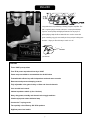
Congratulations on purchasing a Peavey JSX guitar amplifier. The
JSX is a guitar player’s dream come true—an amp that delivers
superior sound quality and high performance for any style of
guitar playing. Only the finest materials are used to create this
great-sounding, rugged, tour-worthy and very unique-looking tone
machine. I hope you like this amp as much as I do!
ENGLISH
Features
• Three 12AX7 preamp tubes
• Four EL34 power amp tubes driven by a 12AX7
• Power amp convertible to accommodate four 6L6GC tubes
• Footswitchable effects loop with independent send and return controls
• Resonance and presence damping controls
• Fully adjustable noise gate circuitry on Ultra and Crunch channels
• Line out with level control
• Cabinet impedance switch (4, 8 or 16 ohms)
• Heavy duty power, standby and channel select toggle switches
• Classic-style power status indicator lamp
• Accutronics™ spring reverb
• Two specially voiced Peavey JSX SP-8 speakers
• High/low power level switch
Joe Satriani
™

8
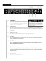
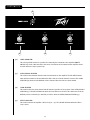
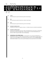
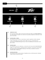
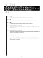
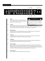
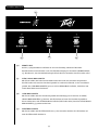
F R O N T PA N E L
(1) POWER SWITCH
This two-way toggle switch applies mains power to the
unit. The red POWER STATUS LAMP (3) will illuminate
when this switch is in the ON position.
(2) STANDBY SWITCH
This two-way toggle switch allows the amp to be placed in STANDBY mode. In the STANDBY position
the tubes stay hot but the amplifier is not operational. Switching to the ON position places the amp in
active mode.
(3) POWER STATUS LAMP
This indicator illuminates when mains power is being supplied to the amp.
(4) PRESENCE
This is used to fine-tune the high frequency range of the speaker enclosure by varying the damping
factor of the amplifier at high frequencies.
(5) RESONANCE
This is used to fine-tune the low frequency range of the speaker enclosure by varying the damping
factor of the amplifier at low frequencies.
(6) MASTER VOLUME
This control sets the overall volume level of the amp. Once the desired balance between the three
channels in the amplifier has been achieved, the entire output level of the unit can be increased or
decreased by rotating this control. Clockwise rotation increases the level; counterclockwise rotation
decreases the level.
(7) MASTER REVERB
This controls the overall reverb level.
1
6
7
5
4 3
2
WARNING
THE ON/OFF SWITCH IN THIS APPARATUS
DOES NOT BREAK BOTH SIDES OF THE MAINS.
HAZARDOUS ENERGY MAY BE
PRESENT INSIDE
THE ENCLOSURE WHEN THE POWER SWITCH IS
IN THE OFF POSITION.

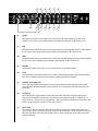
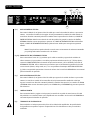
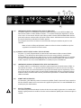
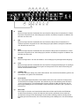
(8) TREBLE
On both the Ultra and Crunch channels, this control varies the high frequency response of the
amplifier. It is an active control (shelving type) and allows approximately 12 dB of boost or cut.
(9) MID
On both the Ultra and Crunch channels, this control varies the mid frequency response of the amplifier.
It is an active control (peak/notch type) and allows approximately 12 dB of boost or cut.
(10) BASS
On both the Ultra and Crunch channels, this control varies the low frequency response of the amplifier.
It is an active control (shelving type) and allows approximately 12 dB of boost or cut.
(11) VOLUME
On all three channels, this control sets the overall level of its respective channel.
(12) GAIN
On both the Ultra and Crunch channels, this controls the input volume level of the channel. Rotating
this control clockwise will increase the amount of preamp distortion and sustain.
(13) CHANNEL ACTIVATION LEDs
These indicators signify which channel is active. Ultra channel activation illuminates the red LED;
Crunch channel activation illuminates the yellow LED; and Clean channel activation illuminates the
green LED.
(14) FAT SWITCH
These two-position toggle switches on the Ultra and Crunch channels modify the low frequency
response of the amplifier and have the most noticeable effect when the guitar is "cleaned up," i.e.
when the guitar's volume control is turned down. This control affects the tightness of the attack; the
attack is sloppier when the switch is in the "FAT" position.
(15) NOISE GATE
This control is shared by the Ultra and Crunch channels and adjusts the effectiveness of the noise
gate circuitry. Noise is reduced more as the control is turned clockwise. Avoid using high settings of
the noise gate when using lower gain settings, since at these settings the decay of the note will be
adversely affected.
6
9
8
8
9
10
10
11
12
1112
13
14
14
15

10
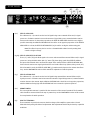
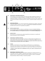
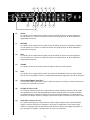
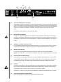
(16) TREBLE
This passive control regulates the high frequencies for the Clean channel.
(17) MID
This passive control regulates the mid frequencies for the Clean channel.
(18) BASS
This passive control regulates the low frequencies for the Clean channel.
(19) HIGH GAIN INPUT
Used for most electronic guitars. It is 6 dB louder than the Low Gain input.
(20) LOW GAIN INPUT
Provided for instruments that have extremely high outputs that tend to overdrive (distort) the High
Gain input. If both inputs are used simultaneously, the output levels are the same (both are Low Gain).
(21) CHANNEL SELECT SWITCH
This three-position toggle switch allows selection between the amplifier’s three channels. LED (13)
illumination indicates which channel is active. Channel switching can also be accomplished by
footswitch. See the FOOTSWITCH section of this manual for explanation of switch operation. The
CHANNEL SELECT SWITCH must be set in the Ultra position in order for the footswitch to operate
properly.
2120
171819
16

11
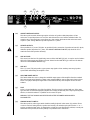
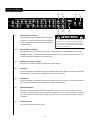
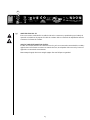
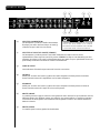
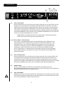
R E A R PA N E L
(22) EFFECTS SEND LEVEL
This calibrated (0 – 10) control sets the level of signal being sent to external effects and/or signal
processors. Clockwise rotation increases the amount of signal being sent; counterclockwise rotation
decreases the amount. For the quietest operation, the EFFECTS SEND LEVEL should be set as high as
possible. Generally, the SEND and RETURN levels should be set in opposite proportions. If the EFFECTS
SEND LEVEL is set low, the EFFECTS RETURN LEVEL (24) should be set high to achieve unity gain.
Note: The effects loop may also be used as a footswitchable volume boost by turning both
controls to higher settings.
(23/24) EFFECTS SEND/EFFECTS RETURN
These 1/4" mono (TS) jacks allow signal to be sent to and returned from external effects and/or signal
processors. Using shielded cables with 1/4" mono (TS) phone plugs, patch from EFFECTS SEND to
the input of the external device and from the output of the external device to EFFECTS RETURN. Only
devices that do not increase signal gain should be used in this effects loop (chorus, delay, reverb, etc.).
If the footswitch is used, the EFFECTS SELECTOR (39) switch must be depressed to activate the effects
loop. See the FOOTSWITCH section of this manual for explanation of switch operation.
(25) EFFECTS RETURN LEVEL
This calibrated (0 – 10) control sets the level of signal being returned from external effects and/or
signal processors. Clockwise rotation increases the amount of signal being returned; counterclockwise
rotation decreases the amount. Again, SEND and RETURN levels should be set in opposite proportions,
with the SEND level being high and the RETURN level low to ensure the quietest operation.
(26) REMOTE SWITCH
This seven-pin DIN connector is provided for the connection of the remote footswitch. The footswitch
cable should be connected before the amp is powered up. See the FOOTSWITCH section of this manual
for an explanation of switch operation.
(27) BIAS TEST TERMINALS
These terminals are provided to measure the bias voltage of the amplifier’s power tubes. A knob
behind the back panel grille allows for adjustment. Bias adjustment should only be done by a qualified
technician.
CAUTION
FUSE
FUS
E
26
22
23
24
25
27

12
(28) CABINET IMPEDANCE SWITCH
This three-position switch allows appropriate selection of speaker cabinet impedance. If two
enclosures of equal impedance are used, the switch should be set to half the individual value. For
example, two 16 ohm enclosures necessitate an 8 ohm setting, while two 8 ohm enclosures would
require a 4 ohm setting. Minimum speaker impedance is 4 ohms.
(29) SPEAKER OUTPUTS
These paralleled 1/4" mono (TS) jacks are provided for the connection of speaker enclosure(s). Again,
minimum speaker impedance is 4 ohms. The CABINET IMPEDANCE SWITCH (28) should be set to
match the load of the speaker cabinet(s).
(30) LINE OUT LEVEL
This control sets the level of signal being sent out of the LINE OUT (31) jack. It may be used to balance
the level of slave power amp/speaker systems driven from the LINE OUT (31) to the level of cabinets
driven from the SPEAKER OUTPUTS (29).
(31) LINE OUT
This 1/4" mono (TS) jack provides a post-power amp signal to drive another power amp/speaker
system while maintaining the amplifier’s tone.
(32) HIGH/LOW POWER SWITCH
This switch allows the user to change the available output power of the amplifier from the standard
full power output rating (HIGH) to a lower power output (LOW) for venues that require lower volume
levels or for players who prefer high levels of distortion from the power amplifier section at lower
volumes.
(33) FUSE
A fuse is located within the cap of the fuse holder. This fuse must be replaced with one of the same
type and value to avoid damaging the amplifier and voiding the warranty. If the amp repeatedly blows
the fuse, it should be taken to a qualified service center for repair.
WARNING: THE FUSE SHOULD ONLY BE REPLACED AFTER THE POWER CORD HAS BEEN
DISCONNECTED.
(34) GROUND POLARITY SWITCH
This three-position, rocker-type switch should normally be placed in the center (0) position. If hum
or noise is noticed coming from the speaker enclosure(s), the switch may be placed in the “+” or “-”
position to minimize hum/noise. If changing the polarity does not alleviate the problem, consult your
authorized Peavey dealer, the Peavey factory or a qualified service technician.
CAUTION
FUSE
FUS
E
33
28
29
30
31
32
34

13
(35) IEC MAINS CONNECTOR
This is a standard IEC power connector. An AC mains cord with the appropriate AC plug and ratings for
the intended operating voltage is included in the carton. The mains cord should be connected to the
amplifier before connecting to a suitable AC outlet.
U.S DOMESTIC AC MAINS CORD
The mains cord supplied with the unit is a heavy duty, three-conductor type with a conventional 120
VAC plug with ground pin. If the outlet used does not have a ground pin, a suitable grounding adapter
should be used and the third wire should be properly grounded.
Never break off the ground pin on any equipment. It is provided for your safety.
NOTE FOR UK ONLY:
If the colors of the wires in the mains lead of this unit do not correspond with the colored markings identifying
the terminals in your plug, proceed as follows: (1) The wire that is colored green and yellow must be connected
to the terminal that is marked by the letter E, the earth symbol or colored green or green and yellow; (2) The
wire that is colored blue must be connected to the terminal that is marked with the letter N or the color black;
(3) The wire that is colored brown must be connected to the terminal that is marked with the letter L or the
color red.
CAUTION
FUSE
FUS
E
35

14
F O OT S W I T C H
(36) CABLE CONNECTOR
This seven-pin DIN connector is provided for connecting the footswitch to the amplifier REMOTE
SWITCH (26) via the cable included in the carton. Connections at the switch and the amplifier should
be made before the amp is powered up.
(37) ULTRA/CRUNCH SELECTOR
This switch selects between the Ultra and Crunch channels on the amplifier. The LED will illuminate
when the Ultra channel is selected. When the LED is dark, the Crunch channel is selected. The CLEAN
SELECTOR (38) must be in the BYPASS mode to activate either the Ultra or Crunch channel.
(38) CLEAN SELECTOR
This switch selects the Clean channel and will activate regardless of the position of the ULTRA/CRUNCH
SELECTOR (37). The LED will illuminate when the Clean channel is selected. This switch must be in the
BYPASS position, indicated by a dark LED, in order to utilize the ULTRA/CRUNCH SELECTOR (37).
(39) EFFECTS SELECTOR
This switch activates the amplifier’s effects loop (22 – 25). The LED will illuminate when the effects
loop is active.
37
39
36
38
Page is loading ...

16
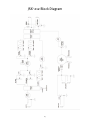
JSX 212
SPECIFICATIONS
Note: For proper ventilation‚
allow 24" clearance from
nearest combustible surface.
POWER AMPLIFIER SECTION:
Tubes:
Four EL34 tubes with 12AX7 driver
Rated Power & Load:
130 watts RMS into 16, 8 or 4 ohms
Power @ Clipping:
(typically @ 5% THD, 1 kHz, 120 VAC line)
130 watts RMS into 16, 8 or 4 ohms
Frequency Response:
+/-3 dB, 50 Hz to 20 kHz @ 90 watts RMS
into 8 ohms
Hum & Noise:
Greater than 76 dB below rated power
Power Consumption:
Domestic: 400 watts, 50/60 Hz, 120 V AC
Export: 400 watts, 60 Hz, 220-230/240 V AC
PREAMP SECTION:
Tubes:
Three 12AX7 tubes
The following specs are measured @ 1 kHz
with the controls preset as follows:
All EQ controls @ 5
Ultra & Crunch Volumes @ 10
Master Volume @ 5
Resonance and Presence controls @ 5
Effects Send @ 0
Effects Return @ 10
Nominal levels are with Gain @ 5
Minimum levels are with Gain @ 10
All levels increased by 6 dB if using
Low Gain input
Clean Channel:
Nominal Input Level: -10 dBV, 300 mV RMS
Minimum Input Level: -22 dBV, 80 mV RMS
Maximum Input Level: 0 dBV, 1 .0 mV RMS
Crunch Channel:
Nominal Input Level: -60 dBV, 1 mV RMS
Minimum Input Level: -90 dBV, 0.03 mV RMS
Ultra Channel:
Nominal Input Level: -70 dBV, 0.3 mV RMS
Minimum Input Level: -90 dBV, 0.03 mV RMS
Effects Send:
Load Impedance: 47 k ohms or greater
Minimum Output:
-10 dBV, 300 mV RMS
Maximum Output:
0 dBV, 1 V RMS
Effects Return:
Impedance: High Z, 80 k ohms
Minimum Input Sensitivity:
-10 dBV, 300 mV RMS
Maximum Input Sensitivity:
0 dBV, 1 V RMS
Line Output:
Load Impedance: 47 k ohms or greater
Adjustable Output:
+/- 20 dBV, 0.1V RMS-10 V RMS
Remote Footswitch:
Special three-button metal footswitch
with LED indicators and detachable cord
(supplied) selects between three channels
and bypasses effects loop
System Hum & Noise @ Nominal Level:
(Clean channel - 20 Hz to 20 kHz unweighted)
Greater than 74 dB below rated power
(Adjustable noise gate circuitry for Ultra & Crunch)
Equalization:
Custom bass, mid & treble passive-type EQ
on Clean channel
Separate active +/-12 dB bass, mid & treble
EQs on Ultra & Crunch channels
Fat switches on Ultra & Crunch modifies low
frequency response
Resonance and presence damping EQ
controls in power amp
Dimensions & Weight:
20.5" (521 mm) H x 26.5" (673 mm) W x
11" (279 mm) D
85.3 lbs. (38.7 kg)
™
Page is loading ...
Page is loading ...
Page is loading ...
Page is loading ...
Page is loading ...
Page is loading ...
Page is loading ...
Page is loading ...
Page is loading ...
Page is loading ...
Page is loading ...
Page is loading ...
Page is loading ...
Page is loading ...
Page is loading ...
Page is loading ...
Page is loading ...
Page is loading ...
Page is loading ...
Page is loading ...
Page is loading ...
Page is loading ...
Page is loading ...
Page is loading ...
Page is loading ...
Page is loading ...
Page is loading ...
Page is loading ...
Page is loading ...
Page is loading ...

47
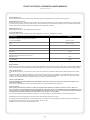
PEAVEY ELECTRONICS CORPORATION LIMITED WARRANTY
Effective Date: July 1, 1998
What This Warranty Covers
Your Peavey Warranty covers defects in material and workmanship in Peavey products purchased and serviced in the U.S.A. and Canada.
What This Warranty Does Not Cover
The Warranty does not cover: (1) damage caused by accident, misuse, abuse, improper installation or operation, rental, product modification or neglect; (2) dam-
age occurring during shipment; (3) damage caused by repair or service performed by persons not authorized by Peavey; (4) products on which the serial number
has been altered, defaced or removed; (5) products not purchased from an Authorized Peavey Dealer.
Who This Warranty Protects
This Warranty protects only the original retail purchaser of the product.
How Long This Warranty Lasts
The Warranty begins on the date of purchase by the original retail purchaser. The duration of the Warranty is as follows:
Product Category Duration
Guitars/Basses, Amplifiers, Pre-Amplifiers, Mixers, Electronic
Crossovers and Equalizers 2 years *(+ 3 years)
Drums 2 years *(+ 1 year)
Enclosures 3 years *(+ 2 years)
Digital Effect Devices and Keyboard and MIDI Controllers 1 year *(+ 1 year)
Microphones 2 years
Speaker Components (incl. speakers, baskets, drivers,
diaphragm replacement kits and passive crossovers)
and all Accessories 1 year
Tubes and Meters 90 days
[*Denotes additional warranty period applicable if optional Warranty Registration Card is completed and returned to Peavey by original retail purchaser within 90 days of purchase.]
What Peavey Will Do
We will repair or replace (at Peavey's discretion) products covered by warranty at no charge for labor or materials. If the product or component must be shipped to
Peavey for warranty service, the consumer must pay initial shipping charges. If the repairs are covered by warranty, Peavey will pay the return shipping charges.
How To Get Warranty Service
(1) Take the defective item and your sales receipt or other proof of date of purchase to your Authorized Peavey Dealer or Authorized Peavey Service Center.
OR
(2) Ship the defective item, prepaid, to Peavey Electronics Corporation, International Service Center, 412 Highway 11 & 80 East, Meridian, MS 39301 or Peavey
Canada Ltd., 95 Shields Court, Markham, Ontario, Canada L3R 9T5. Include a detailed description of the problem, together with a copy of your sales receipt or
other proof of date of purchase as evidence of warranty coverage. Also provide a complete return address.
Limitation of Implied Warranties
ANY IMPLIED WARRANTIES, INCLUDING WARRANTIES OF MERCHANTABILITY AND FITNESS FOR A PARTICULAR PURPOSE, ARE LIMITED IN DURATION TO THE
LENGTH OF THIS WARRANTY.
Some states do not allow limitations on how long an implied warranty lasts, so the above limitation may not apply to you.
Exclusions of Damages
PEAVEY'S LIABILITY FOR ANY DEFECTIVE PRODUCT IS LIMITED TO THE REPAIR OR REPLACEMENT OF THE PRODUCT, AT PEAVEY'S OPTION. IF WE ELECT TO
REPLACE THE PRODUCT, THE REPLACEMENT MAY BE A RECONDITIONED UNIT. PEAVEY SHALL NOT BE LIABLE FOR DAMAGES BASED ON INCONVENIENCE, LOSS OF
USE, LOST PROFITS, LOST SAVINGS, DAMAGE TO ANY OTHER EQUIPMENT OR OTHER ITEMS AT THE SITE OF USE, OR ANY OTHER DAMAGES WHETHER INCIDENTAL,
CONSEQUENTIAL OR OTHERWISE, EVEN IF PEAVEY HAS BEEN ADVISED OF THE POSSIBILITY OF SUCH DAMAGES.
Some states do not allow the exclusion or limitation of incidental or consequential damages, so the above limitation or exclusion may not apply to you.
This Warranty gives you specific legal rights, and you may also have other rights which vary from state to state.
If you have any questions about this warranty or service received or if you need assistance in locating an Authorized Service Center, please contact the Peavey
International Service Center at (601) 483-5365 / Peavey Canada Ltd. at (905) 475-2578.
Features and specifications subject to change without notice.

Features and specifications subject to change without notice.
Peavey Electronics Corporation • 711 A Street • Meridian • MS • 39301
(601) 483-5365 • FAX (601) 486-1278 • www.peavey.com
©2005
80304951
-
 1
1
-
 2
2
-
 3
3
-
 4
4
-
 5
5
-
 6
6
-
 7
7
-
 8
8
-
 9
9
-
 10
10
-
 11
11
-
 12
12
-
 13
13
-
 14
14
-
 15
15
-
 16
16
-
 17
17
-
 18
18
-
 19
19
-
 20
20
-
 21
21
-
 22
22
-
 23
23
-
 24
24
-
 25
25
-
 26
26
-
 27
27
-
 28
28
-
 29
29
-
 30
30
-
 31
31
-
 32
32
-
 33
33
-
 34
34
-
 35
35
-
 36
36
-
 37
37
-
 38
38
-
 39
39
-
 40
40
-
 41
41
-
 42
42
-
 43
43
-
 44
44
-
 45
45
-
 46
46
-
 47
47
-
 48
48


Peavey JSX 212 User manual
- Category
- Musical Instrument Amplifier
- Type
- User manual
- This manual is also suitable for
Ask a question and I''ll find the answer in the document
Finding information in a document is now easier with AI
in other languages
- français: Peavey JSX 212 Manuel utilisateur
- español: Peavey JSX 212 Manual de usuario
- Deutsch: Peavey JSX 212 Benutzerhandbuch
Related papers
-
Peavey JSX 212 User manual
-
-
-
Peavey Classic 30 User manual
-
-
 Peavy PV Series Power Amplifer Owner's manual
-
Peavey CS 4000 Owner's manual
-
 Peavy Classic 50 410 User manual
-
-


Other documents
-
Crest Audio CC 4000 User manual
-
 Architectural Acoustics IP-Six User manual
-
Crest Audio CPX 3800 User manual
-
Omnitronic COMBO-70 User manual
-
-
Omnitronic MPZ-180.6 User manual
-
-
Omnitronic DX-2222 User manual
-
 HH Electronics HPT-112 User manual
-
Omnitronic PAS-210 II User manual

