Page is loading ...

Questions?
Help is just a moment away!
Call: Generator Helpline
877-369-9400
Monday through Friday 8:00 AM to 5:00 PM Central Time
Generator Systems
Installation Manual
GEN12AD-V

Thank you for purchasing this quality-built Rheem / Ruud generator. We are pleased that you’ve placed your confidence in the
Rheem or Ruud brand. When operated and maintained according to the instructions in the operator’s manual, your generator
will provide many years of dependable service.
This manual contains safety information to make you aware of the hazards and risks associated with generator systems and
how to avoid them. This generator system is designed and intended only for use as an optional standby system that provides
an alternate source of electric power and to serve loads such as heating, refrigeration systems, and communication systems
that, when stopped during any power outage, could cause discomfort or inconvenience. Save these original instructions for
future reference.
This generator system requires professional installation before use. Your installer should follow the instructions completely
Where to Find Us
You never have to look far to find support and service for your generator. Consult your Yellow Pages. There are many
Rheem and Ruud authorized service dealers who provide quality service. You can also contact customer service by phone at
877-369-9400 between 8:00 AM and 5:00 PM CT.
For Future Reference
Please fill out the information below and keep with your receipt to assist in unit identification for future purchase issues.
Date of Purchase __________________________
Generator
Model Number __________________________
Model Revision __________________________
Serial Number __________________________
Engine
Model Number __________________________
Serial Number __________________________
© 2012. All rights reserved. No part of this material
may be reproduced or transmitted in any form by any means
without the express written permission of Rheem Manufacturing
Company.

3
Table of Contents
Important Safety Instructions........................4
Installation ....................................7
Equipment Description.........................................7
Home Owner Responsibilities ...................................7
Installing Dealer/Contractor Responsibilities ........................7
Cold Weather Kit .............................................7
Unpacking Precautions ........................................7
Delivery Inspection............................................7
Installation Checklist ..........................................8
Shipment Contents............................................8
Generator Placement ..........................................9
Other General Location Guidelines................................9
Placement of Standby Generator to REDUCE THE RISK OF FIRE .......12
Electrical and Fuel Inlet Locations ...............................15
Lifting the Generator .........................................15
Access Ports ...............................................16
The Gaseous Fuel System .....................................18
Fuel Consumption ...........................................19
Fuel Pressure ...............................................19
Power Loss ................................................19
Fuel Pipe Sizing .............................................19
Fuel Conversion .............................................19
System Connectors ..........................................20
Generator AC Connection System ...............................21
Grounding the Generator ......................................21
Utility Circuit Connection ......................................21
Transfer Switch Communication ................................22
Fault Detection System .......................................22
System Control Panel.........................................22
Concrete Slab (Optional) ......................................23
Gravel Base (Optional) ........................................23
Final Installation Considerations ................................23
Initial Start-up (No Load)......................................24
Engine Adjustment...........................................25
12000 Watt Schematic Diagram ................................26
12000 Watt Wiring Diagram ...................................27
Operation .................................... 28
Automatic Operation Sequence .................................28
Setting Exercise Timer ........................................28
Installation Inspection ........................................28

4
Save These Instructions
WARNING Running engine gives off carbon monoxide,
an odorless, colorless, poison gas.
Breathing carbon monoxide could result
in death, serious injury, headache, fatigue,
dizziness, vomiting, confusion, seizures, nausea
or fainting.
• Operate this product ONLY outdoors in an area that will
not accumulate deadly exhaust gas.
• Keep exhaust gas away from any windows, doors,
ventilation intakes, soffit vents, crawl spaces, open garage
doors or other openings that can allow exhaust gas
to enter inside or be drawn into a potentially occupied
building or structure.
• Carbon monoxide detector(s) MUST be installed and
maintained indoors according to the manufacturer’s
instructions/recommendations. Smoke alarms cannot
detect carbon monoxide gas.
WARNING Storage batteries give off explosive
hydrogen gas during recharging.
Slightest spark will ignite hydrogen
and cause explosion, resulting
in death, serious injury and/or
property damage.
Battery electrolyte fluid contains acid and is
extremely caustic.
Contact with battery contents could cause severe
chemical burns.
A battery presents a risk of electrical shock and high short
circuit current.
• DO NOT dispose of battery in a fire. Recycle battery.
• DO NOT allow any open flame, spark, heat, or lit cigarette
during and for several minutes after charging a battery.
• DO NOT open or mutilate the battery.
• Wear protective goggles, rubber apron, rubber boots and
rubber gloves.
• Remove watches, rings, or other metal objects.
• Use tools having insulated handles.
Important Safety Instructions
SAVE THESE INSTRUCTIONS - This manual contains
important instructions that should be followed during
installation and maintenance of the generator and batteries.
Safety Symbols and Meanings
The safety alert symbol indicates a potential personal
injury hazard. A signal word (DANGER, WARNING, or
CAUTION) is used with the alert symbol to designate a
degree or level of hazard seriousness. A safety symbol
may be used to represent the type of hazard. The signal
word NOTICE is used to address practices not related to
personal injury.
DANGER indicates a hazard which, if not avoided, will
result in death or serious injury.
WARNING indicates a hazard which, if not avoided, could
result in death or serious injury.
CAUTION indicates a hazard which, if not avoided, could
result in minor or moderate injury.
NOTICE addresses practices not related to personal injury.
The manufacturer cannot possibly anticipate every possible
circumstance that might involve a hazard. The warnings in
this manual, and the tags and decals affixed to the unit are,
therefore, not all-inclusive. If you use a procedure, work
method or operating technique that the manufacturer does
not specifically recommend, you must satisfy yourself that
it is safe for you and others. You must also make sure that
the procedure, work method or operating technique that you
choose does not render the generator system unsafe.
Explosion
Fire
Electrical Shock
Rotating Parts
Hot Surface
Toxic Fumes
Chemical BurnExplosive PressureAuto Start
Lift Hazard
Read Manual
WARNING The engine exhaust from this product
contains chemicals known to the State of California to
cause cancer, birth defects, or other reproductive harm.
WARNING Certain components in this product and
related accessories contain chemicals known to the State
of California to cause cancer, birth defects, or other
reproductive harm. Wash hands after handling.

5
WARNING Generator produces hazardous voltage.
Failure to properly ground generator could result
inelectrocution.
Failure to isolate generator from utility power could
result in death or serious injury to electric utility
workers due to backfeed of electrical energy.
• When using generator for backup power, notify
utility company.
• DO NOT touch bare wires or bare receptacles.
• DO NOT use generator with electrical cords which are
worn, frayed, bare or otherwise damaged.
• DO NOT handle generator or electrical cords while
standing in water, while barefoot, or while hands or
feet are wet.
• If you must work around a unit while it is operating,
stand on an insulated dry surface to reduce the risk of
a shock hazard.
• DO NOT allow unqualified persons or children to operate
or service generator.
• In case of an accident caused by electrical shock,
immediately shut down the source of electrical power and
contact the local authorities. Avoid direct contact with
the victim.
• Despite the safe design of the generator, operating this
equipment imprudently, neglecting its maintenance or
being careless could cause possible injury or death.
• Remain alert at all times while working on this equipment.
Never work on the equipment when you are physically
or mentally fatigued.
• Before performing any maintenance on the generator,
disconnect the battery cable indicated by a NEGATIVE,
NEG or (-) first. When finished, reconnect that cable last.
• After your system is installed, the generator may crank
and start without warning any time there is a power
failure. To prevent possible injury, always set the
generator’s system switch to OFF, remove the service
disconnect from the disconnect box AND remove the
15 Amp fuse BEFORE working on the equipment.
WARNING Propane and Natural Gas are extremely
flammable and explosive, which could cause
burns, fire or explosion resulting in death,
serious injury and/or property damage.
• Install the fuel supply system according to NFPA 37 and
other applicable fuel-gas codes.
• Before placing the generator into service, the fuel system
lines must be properly purged and leak tested.
• After the generator is installed, you should inspect the fuel
system periodically.
• NO leakage is permitted.
• DO NOT operate engine if smell of fuel is present or other
explosive conditions exist.
• DO NOT smoke around the generator. Wipe up any oil
spills immediately. Ensure that no combustible materials
are left in the generator compartment. Keep the area near
the generator clean and free of debris.
WARNING Hazardous Voltage - Contact with power
lines could cause electric shock or burns,
resulting in death or serious injury.
Lifting Hazard / Heavy Object - Could result
in serious injury.
• If lifting or hoisting equipment is used, DO NOT contact
any power lines.
• DO NOT lift or move generator without assistance.
• Use lifting pipes as described in Lifting the Generator.
• DO NOT lift unit by roof as damage to generator
will occur.

6
WARNING Starter and other rotating parts could
entangle hands, hair, clothing, or accessories
resulting in serious injury.
• NEVER operate generator without protective housings,
covers, or guards in place.
• DO NOT wear loose clothing, jewelry or anything that
could be caught in the starter or other rotating parts.
• Tie up long hair and remove jewelry.
• Before servicing, remove 15 Amp fuse from control panel
and disconnect Negative (NEG or -) battery cable.
CAUTION Installing the 15A fuse could cause the
engine to start at any time without warning
resulting in minor or moderate injury.
• Observe that the 15 Amp fuse has been removed from the
control panel for shipping.
• DO NOT install this fuse until all plumbing and wiring has
been completed and inspected.
CAUTION Excessively high operating speeds could
result in minor injury and/or equipment damage,
Excessively low speeds impose a heavy load on generator.
• DO NOT tamper with governed speed. Generator supplies
correct rated frequency and voltage when running at
governed speed.
• DO NOT modify generator in any way.
NOTICE Improper treatment of generator could damage it
and shorten its life.
• Use generator only for intended uses.
• If you have questions about intended use, contact your
authorized dealer.
• Operate generator only on level surfaces.
• Adequate, unobstructed flow of cooling and ventilating air
is critical to correct generator operation.
• The access panels/doors must be installed whenever the
unit is running.
• DO NOT expose generator to excessive moisture, dust,
dirt, or corrosive vapors.
• Remain alert at all times while working on this equipment.
Never work on the equipment when you are physically
or mentally fatigued.
• DO NOT start engine with air cleaner or air cleaner
cover removed.
• DO NOT insert any objects through cooling slots.
• DO NOT use the generator or any of its parts as a step.
Stepping on the unit could cause stress and break parts.
This may result in dangerous operating conditions from
leaking exhaust gases, fuel leakage, oil leakage, etc.
• If connected devices overheat, turn them off and
disconnect them from generator.
Shut off generator if
- electrical output is lost;
- equipment sparks, smokes, or emits flames;
- unit vibrates excessively;
- unit makes unusual noises.
WARNING
Exhaust heat/gases could ignite combustibles
or structures resulting in death, serious
injury and/or property damage. Contact with
muffler area could cause burns resulting in
serious injury.
• DO NOT touch hot parts and AVOID hot exhaust gases.
• Allow equipment to cool before touching.
• Exhaust outlet side of weatherproof enclosure must
have at least 5 ft. (1.5 m) minimum clearance from any
structure, shurbs, trees or any kind of vegetation.
• Standby generator weatherproof enclosure must be at
least 5 ft. (1.5 m) from windows, doors, any wall opening,
shrubs or vegetation over 12 inches (30.5 cm) in height.
• Standby generator weatherproof enclosure must have a
minimum of 5 ft. (1.5 m) overhead clearance from any
structure, overhang or trees.
• DO NOT place weatherproof enclosure under a deck or
other type of structure that may confine airflow.
• Use only flexible steel fuel line provided. Connect provided
fuel line to generator, DO NOT use with or substitute any
other flexible fuel line.
• Smoke detector(s) MUST be installed and maintained
indoors according to the manufacturer’s instructions/
recommendations. Carbon monoxide alarms cannot
detect smoke.
• Keep at least minimum distances shown in General
Location Guidelines to insure for proper generator cooling
and maintenance clearances.
• It is a violation of California Public Resource Code,
Section 4442, to use or operate the engine on any forest-
covered, brush-covered, or grass-covered land unless
the exhaust system is equipped with a spark arrester, as
defined in Section 4442, maintained in effective working
order. Other states or federal jurisdictions may have
similar laws.
Contact the original equipment manufacturer, retailer, or
dealer to obtain a spark arrester designed for the exhaust
system installed on this engine.
• Replacement parts must be the same and installed in the
same position as the original parts.

7
Installation
Equipment Description
This product is only for use as an optional generator system
which provides an alternate source of electric power and
to serve loads such as heating, refrigeration systems, and
communication systems that, when stopped during any
power outage, could cause discomfort or inconvenience.
NOTICE This product does NOT qualify for either an
emergency standby or legally required standby system as
defined by NFPA 70 (NEC).
• Emergencygeneratorsystemsareintendedto
automatically supply illumination, power, or both, to
designated areas and equipment in the event of failure
of the normal supply. Emergency systems may also
provide power for such functions as ventilation where
essential to maintain life, where current interruption
of the normal supply would produce serious life
safety or health hazards.
• LegallyRequiredstandbygeneratorsystemsare
intended to automatically supply power to selected
loads in the event of failure of the normal source
which could create hazards or hamper rescue or fire-
fighting operations.
Every effort has been made to ensure that information in this
manual is accurate and current. However, we reserve the
right to change, alter, or otherwise improve the product and
this document at any time without prior notice.
Only current licensed electrical and plumbing professionals
should attempt home generator system installations.
Installations must strictly comply with all applicable codes,
industry standards, laws and regulations.
Owner Responsibilities
• Readandfollowtheinstructionsgiveninthe
operator’smanual.
• Followaregularscheduleinmaintaining,caringfor
and using your generator, as specified in the operator’s
manual.
• Carbonmonoxidedetector(s)MUSTbeinstalledand
maintained indoors according to the manufacturer’s
instructions/recommendations. Smoke alarms cannot
detect carbon monoxide gas.
• Smokedetector(s)MUSTbeinstalledandmaintained
indoors according to the manufacturer’s instructions/
recommendations. Carbon monoxide alarms cannot
detect smoke.
If you have questions about intended use, ask your installer
or dealer or call 877-369-9400 between
8:00 AM and 5:00PM CT.
Installing Dealer/Contractor Responsibilities
• Readandobservethesafetyrules.
• InstallonlyanULapprovedtransferswitchthatis
compatible with the generator.
• Readandfollowtheinstructionsgiveninthis
installation and start-up manual.
• Installationmuststrictlycomplywithallapplicable
codes, industry standards, laws, and regulations.
• Allowsufficientroomonallsidesofthegeneratorfor
maintenance and servicing.
Cold Weather Kit
If operating the generator below 40°F (5°C), it is HIGHLY
RECOMMENDED that a Model 6030A Cold Weather Kit
(includes oil warmer and battery warmer) be installed. These
items are available at your local servicing dealer.
If you need more information on this matter, please call
(877) 369-9400, between 8:00 AM and 5:00 PM CT.
Unpacking Precautions
The unit is shipped bolted to its mounting pad, ready
for installation. Avoid damage from dropping, bumping,
collision, etc. Store and unpack carton with the proper side
up, as noted on the shipping carton.
Delivery Inspection
After removing the carton, carefully inspect the generator for
any damage that may have occurred during shipment.
If loss or damage is noted at time of delivery, have the
person(s) making delivery note all damage on the freight
bill and affix his signature under the consignor’s memo of
loss or damage. If loss or damage is noted after delivery,
separate the damaged materials and contact the carrier
for claim procedures. Parts damaged in shipping are
notwarranted.
40°F (5°C)

8
Shipment Contents
The generator is supplied with:
• Pre-attachedmountingpad
• Fully-servicedoil/lubricatingsystem
• Flexiblesteelfuelline
• Installationandstart-upmanual
• Operator’smanual
• Spareaccessdoorkeys
• Spare15AmpATO-typefuse
• Two-pinconnectorplug
• Ten-pinconnectorplug
• Liftingholdplugs(4)
• LPconversionjet
• Batterytie-downstrap
• RemoteLEDindicatorkit(LED/plate/screws)
Not Included:
• Carbonmonoxidedetector(s)
• Smokedetector(s)
• Startingbattery(seepage24)
• Connectingwireandconduit
• Fuelsupplyvalves/plumbing
• Crane,liftingstraps,chainsorcables
• Two48”lengthsof1”pipe(NOTconduit)
• Holepunchesfor16gasteel
• Torquescrewdriver,5to50inch-poundrange
• Voltage/frequencymeter

9
Installation Checklist
Carbon Monoxide (CO) Detector/Smoke Detector
Carbon Monoxide (CO) detector(s) installed and in
working order.
Smoke detector(s) installed and in working order.
Placement
Required permits have been obtained.
Generator placed in a Carbon Monoxide (CO) safe zone.
See Placement of Standby Generator to Reduce the Risk
of Carbon Monoxide Poisoning.
Generator placed in a fire safe zone. See Placement of
Standby Generator to Reduce the Risk of Fire.
Generator placed in a water damage safe zone. See Other
General Location Guidelines.
Generator placed in a utility safe zone. See Other General
Location Guidelines.
Generator placed in a debris free zone. See Other General
Location Guidelines.
Generator placed on flat ground with provisions for water
drainage.See Other General Location Guidelines.
Fuel
Generator is connected to fuel source with flexible fuel
line, has no fuel leaks and conforms to local codes. See
The Gaseous Fuel System.
Proper fuel pressure has been measured with all gas
appliances operating. See The Gaseous Fuel System.
Fuel system has been configured for the proper fuel
supply: Natural gas (NG) or liquefied petroleum ( LP). See
Fuel Conversion.
Fuel type: (circle one) NG LP
Fuelpipesizeused:(circleone)3/4”1”1-1/4”1-1/2”
See NFPA 54.
Fuel pressure at fuel inlet port with generator on and at
full load and all gas appliances turned on and operating
____________________.
Electrical
Generator neutral is connected to Automatic Transfer
Switch. See Generator AC Connection System.
Generator is grounded. See Grounding the Generator and
NFPA 70.
Generator is connected to the transfer switch with the
specified wiring. See Utility Circuit Connection and
Transfer Switch Communication.
Generator is connected to the transfer switch with the
specified wiring. #18AWG twisted pair wiring from the
generator control panel to the transfer switch is installed
in a separate conduit from high voltage wires unless
the insulation rating on all wiring is rated for 600V See
Transfer Switch Communication.
Dipswitches in most transfer switches must be set to
correspond to the wattage of the generator. See Transfer
Switch Operator/Installation Manual.
Operation
Cold weather kit is installed in temperatures below
40°F (5°C). See Cold Weather Kit.
Correct battery type is installed and fully charged. See
Final Installation Considerations.
Generator engine oil level is at full mark. See Final
Installation Considerations.
Circuit breaker is in the ON position.
Utility was shut off to test the operation of generator
and transfer switch. Note any fault codes and make
corrections as required.
AC Voltage Output___________________________.
Frequency Output___________________________.
Owner Information
Name: _______________________________________
Address: ______________________________________
_____________________________________________
Phone/e-mail: __________________________________
Unit Information
Generator Model: _______________________________
Generator Serial Number: ________________________
Installing Contractor Information
Name: _______________________________________
Address: ______________________________________
_____________________________________________
Phone/FAX: ___________________________________
Electrician: ___________________________________
Signature: ____________________________________
Plumber: _____________________________________
Signature: ____________________________________
Inspector Information
Name: _______________________________________
Address: ______________________________________
_____________________________________________
Title: _________________________________________
Inspection Date: ________________________________
This generator has been installed per the manufacturer’s
instructions:
Installing Contractor Signature: ____________________________
Date: _________________________________________________

10
PAGE LEFT INTENTIONALLY BLANK

11
Generator Placement
Before installing generator, consult with home owner and
convey the following requirements, which must be satisfied
before the installation is complete.
There are two equally important safety concerns in regards to
carbon monoxide poisoning and fire. There are also several
general location guidelines that must be met before the
installation in considered complete.
Exhaust Side of the Generator
A - Exhaust outlet side of weatherproof enclosure
B - Weatherproof enclosure opposite exhaust side
Other General Location Guidelines
• Placethestandbygeneratorinapreparedlocationthat
is flat and has provisions for water drainage.
• Installthestandbygeneratorinalocationwheresump
pump discharge, rain gutter downspouts, roof run-off,
landscape irrigation, or water sprinklers will not flood
the unit or spray the enclosure and enter any air inlet or
outlet openings.
• Installthestandbygeneratorwhereitwillnotaffector
obstruct and services including covered, concealed and
underground, such as telephone, electric, fuel (natural
gas/ LPG vapor), irrigation, air conditioning, cable,
septic, sewer, well and so forth.
• Installthestandbygeneratorwhereleaves,grass,
snow, etc. will not obstruct air inlet and outlet
openings. If prevailing winds will cause blowing or
drifting, you may need to construct a windbreak to
protect the unit.
National Fire Protection Association (NFPA)
Standard NFPA 37 Requirements and Testing
Requirements:
NFPA 37 2010, section 4. 1. 4, Engines Located Outdoors.
Engines, and their weatherproof housings if provided, that are
installed outdoors shall be located at least 1.5m (5 ft) from
openings in walls and at least 1.5 m (5 ft) from structures
having combustible walls. A minimum separation shall not be
required where either of the following conditions exist:
1. The adjacent wall of the structure has a fire resistance
rating of at least 1 hour.
2. The weatherproof enclosure is constructed
of noncombustible materials and it has been
demonstrated that a fire within the enclosure will not
ignite combustible materials outside the enclosure. *
* Annex A Explanatory Material
A.4.1.4 (2) Means of demonstrating compliance are by
means of full-scale fire tests or by calculation procedures,
such as those given in NFPA 555, Guide on Methods for
Evaluating Potential for Room Flashover.
To comply with condition 2 above the weatherproof enclosure
has been constructed completely of non-combustible
materials and full-scale fire tests have been conducted to
demonstrate that a fire within the enclosure will not ignite
combustible materials outside the enclosure.
WARNING Running engine gives off carbon monoxide,
an odorless, colorless, poison gas.
Breathing carbon monoxide could result in death
serious injury, headache, fatigue, dizziness,
vomiting, confusion, seizures, nausea or fainting.
• Operate this product ONLY outdoors in an area that wil
not accumulate deadly exhaust gas.
• Keep exhaust gas away from any windows, doors,
ventilation intakes, soffit vents, crawl spaces, open garage
doors or other openings that can allow exhaust gas
to enter inside or be drawn into a potentially occupied
building or structure.
• Carbon monoxide detector(s) MUST be installed and
maintained indoors according to the manufacturer’s
instructions/recommendations. Smoke alarms cannot
detect carbon monoxide gas.
B
A

12
All fossil fuel burning equipment, such as standby
generators, contains carbon monoxide (CO) gas in the
engine exhaust. CO gas is odorless, colorless and tasteless
and is unlikely to be noticed until a person is overcome.
CO gas can kill you so it is required that the following is
included as part of the installation:
• Installgeneratoroutdoorsinanareathatwillnot
accumulate deadly exhaust gas.
• DONOTinstallgeneratorwhereexhaustgascould
accumulate and enter inside or be drawn into a
potentially occupied building or structure.
• BylawitisrequiredinmanystatestohaveaCarbon
Monoxide (CO) detector in operating condition in
your home. Carbon monoxide detector(s) (A) MUST
be installed and maintained indoors according to the
manufacturer’s instructions / recommendations. A CO
monitor is an electric device that detects hazardous
levels of CO. When there is a buildup of CO, the
monitor will alert the occupants by flashing visual
indicator light and alarm. Smoke alarms cannot detect
CO gas.
• Yourneighbor(s)homemaybeexposedtotheengine
exhaust from your standby generator and must be
considered when installing your standby generator.
• Ensureexhaustgasiskeptawayfrom:
B - windows
C - doors
D - ventilation intakes
E - soffit vents
F - garage doors
G - crawl spaces or other openings that can allow
exhaust gas to enter inside or be drawn into a
potentially occupied building or structure.
Placement of Standby Generator to REDUCE THE RISK OF CARBON MONOXIDE POISONING
The arrows in the figure below point to POTENTIAL points of entry for Carbon Monoxide Gas.
A
F
C
D
B
E
G

13
• Directthestandbygeneratorexhaustawayfromor
parallel to the building or structure. DO NOT direct
the generator exhaust towards a potentially occupied
building, structure, windows, doors, ventilation intakes,
soffit vents, crawl spaces, open garage doors or other
openings where exhaust gas could accumulate and
enter inside or be drawn into potentially occupied
building or structure.
• DONOTplacestandbygeneratorinanyareawhere
leaves or debris normally accumulates. Position
standby generator in an area where winds will carry
the exhaust gas away from any potentially occupied
building or structure.
ENGINE
EXHAUST
STANDBY
GENERATOR

14
Placement of Standby Generator to REDUCE THE
RISK OF FIRE
The National Fire Protection Association (NFPA) standard
NFPA 37 establishes criteria for minimizing the hazard
of fire during the installation and operation of stationary
combustion engines. NFPA 37 limits the spacing of an
enclosed generator from openings in walls, structures, and
combustible materials outside the enclosure.
The placement requirements provided are based on
compliance to NFPA 37 2010 section 4.1.4.
Examples of standby generator locations to
reduce the risk of fire:
Legend for Generator Locations to reduce the risk of fire:
A - Standby weatherproof enclosure must be at least
5 ft. (1.5 m) from windows, doors, any wall opening,
shrubs, or vegetation over 12 inches (30.5 cm)
in height.
B - Exhaust oulet side of weatherproof enclosure must
have at least 5 ft. (1.5 m) minimum clearance from any
structure, overhang or trees.
C - Standby weatherproof enclosure must have a
minimum of 5 ft. (1.5 m) overhead clearance from any
structure, overhang, or trees.
D Standby Weatherproof enclosure must have a
minimum of 18 inches (45.7 cm) clearance from any
structures with or without a fire rating.
NOTICE DO NOT place weatherproof enclosure under a deck
or other type of coverend structure that may confine airflow.
Vertical Clearances
WARNING
Exhaust heat/gases could ignite combustibles
or structures resulting in death, serious injury and/
or property damage.
• Exhaust outlet side of weatherproof enclosure must
have at least 5 ft. (1.5 m) minimum clearance from any
structure, shrubs, trees or any kind of vegetation.
• Standby generator weatherproof enclosure must be at
least 5 ft. (1.5 m) from windows, doors, any wall opening,
shrubs or vegetation over 12 inches (30.5 cm) in height.
• Standby generator weatherproof enclosure must have a
minimum of 5 ft. (1.5 m) overhead clearance from any
structure, overhang or trees.
• DO NOT place weatherproof enclosure under a deck or
other type of structure that may confine airflow.
• Use only flexible steel fuel line provided. Connect provided
fuel line to generator, DO NOT use with or substitute any
other flexible fuel line.
• Smoke detector(s) MUST be installed and maintained
indoors according to the manufacturer’s instructions/
recommendations. Carbon monoxide alarms cannot
detect smoke.
• DO NOT place weatherproof enclosure in manner other
than shown in illustrations.
Standby
Exhaust
Direction
Center of Exhaust Panel
Structure
5 ft. (1.5 m)
C
B
5 ft. (1.5 m)

15
Single Structure Installations
Legend for Generator Locations to reduce the risk of fire:
A - Standby weatherproof enclosure must be at least
5 ft. (1.5 m) from windows, doors, any wall opening,
shrubs, or vegetation over 12 inches (30.5 cm)
in height.
B - Exhaust oulet side of weatherproof enclosure
must have at least 5 ft. (1.5 m) minimum clearance
from any structure, overhang or trees.
C - Standby weatherproof enclosure must have a
minimum of 5 ft. (1.5 m) overhead clearance from
any structure, overhang, or trees.
D Standby Weatherproof enclosure must have a
minimum of 18 inches (45.7 cm) clearance from any
structures with or without a fire rating.
NOTICE DO NOT place weatherproof enclosure under a
deck or other type of coverend structure that may
confine airflow.
Standby
Exhaust
Direction
5 ft. (1.5 m) min
5 ft. (1.5 m)
18 in. (45.7 cm) min
A
B
D
Standby
Exhaust
Direction
5 ft. (1.5 m)
5 ft. (1.5 m) min
A A
B
D
NOTICE The figures below show the minimum installation distances allowed to structures and items in the legend.

16
Two Structure Installations
Legend for Generator Locations to reduce the
risk of fire:
A - Standby weatherproof enclosure must
be at least 5 ft. (1.5 m) from windows,
doors, any wall opening, shrubs, or
vegetation over 12 inches (30.5 cm) in
height.
B - Exhaust oulet side of weatherproof
enclosure must have at least 5 ft. (1.5 m)
minimum clearance from any structure,
overhang or trees.
C - Standby weatherproof enclosure must
have a minimum of 5 ft. (1.5 m) overhead
clearance from any structure, overhang,
or trees.
D Standby Weatherproof enclosure
must have a minimum of 18 inches (45.7
cm) clearance from any structures with or
without a fire rating.
NOTICE DO NOT place weatherproof enclosure
under a deck or other type of coverend
structure that may confine airflow.
Standby
Standby
Exhaust
Direction
Exhaust
Direction
5 ft. (1.5 m) min
5 ft. (1.5 m)
5 ft. (1.5 m) min
5 ft. (1.5 m)
18 in. (45.7 cm) min
18 in. (45.7 cm) min
A
A
A
A
B
B
D
D
D
D
NOTICE The figures below show the minimum installation distances allowed to structures and items in the legend.

17
Electrical and Fuel Inlet Locations
The 3/4 inch N.P.T. fuel inlet connector (A) and electrical
inlet location (B) are shown below.
The home generator is shipped already attached to its
mounting pad. Unless mandated by local code, a concrete
slab is not required.
Lifting the Generator
The generator has a shipping weight of approximately 605
pounds (274 kg). Proper tools, equipment and qualified
personnel should be used in all phases of handling and
moving the generator.
Two48”lengthsof1”pipe(C), supplied by the installer, are
required to lift the generator manually. Insert pipes through
the lifting holes (D) located near the unit’s base.
Youmayalsolifttheunitusinga“hookandhoist”method
attached to the lifting pipes, provided that you use a spreader
bar to ensure that the chains or cables DO NOT touch the
generator’s roof.
After unit is in place, fill the lifting holes with the supplied
lifting hole plugs.
WARNING Hazardous Voltage - Contact with power
lines could cause electric shock or burns,
resulting in death or serious injury.
Lifting Hazard / Heavy Object - Could result
in serious injury.
• If lifting or hoisting equipment is used, DO NOT contact
any power lines.
• DO NOT lift or move generator without assistance.
• Use lifting pipes as described in Lifting the Generator.
• DO NOT lift unit by roof as damage to generator
will occur.
A
B
C
D

18
Access Ports
Each generator is shipped with a set of identical keys. These
keys fit the locks that secure the access ports.
To open access door:
1. Insert key into lock of access door and turn key one
quarter turn counterclockwise.
2. Remove key.
To close access door:
1. Close control panel door and insert key into lock and
turn key one quarter turn clockwise.
2. Remove key.
The generator is equipped with a removable roof and
removable side panels to permit simple servicing.
To remove roof and divider:
1. Open the control panel access door.
2. Set generator’s circuit breaker to OFF position.
3. Set control panel system switch to OFF.
4. Remove 15 Amp fuse from control panel.
5. Move roof latch (A) to the left until roof pops up slightly.
6. Lift roof off generator.
7. Rotate 4 knobs 1/4 turn and lift divider off.
8. Replace divider and roof in reverse order.
To remove side panels:
1. Open the control panel access door.
2. Set generator’s circuit breaker to OFF position.
3. Set control panel system switch to OFF.
4. Remove 15 Amp fuse from control panel.
5. Remove roof and divider.
6. Lift latches (B) up on both sides of panel to release.
7. Pull panel upward and out of grooves.
To remove exhaust panel:
1. Remove roof and divider.
2. Remove side panels.
3. Remove 6 screws (C) from exhaust panel.
WARNING Contact with muffler area could cause burns
resulting in serious injury.
• DO NOT touch hot parts and AVOID hot exhaust gases.
• Allow equipment to cool before touching.
B
C
C
C
C
C
A
C

19
4. Pull panel (A) up and out of base.
5. Remove two screws (B) and pull muffler cover off.
6. Replace muffler cover and exhaust panel in
reverse order.
To install side panels:
1. Place panel in grooves and slide down in place.
2. Push latches down on both sides of panel to lock
into place.
3. Replace divider and roof.
B
A

20
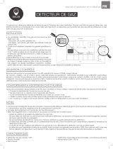
The Gaseous Fuel System
The information below is provided to assist gaseous fuel
system technicians in planning installations. In no way
should this information be interpreted to conflict with
applicable fuel gas codes. Consult with your local fuel
supplier or Fire Marshall if questions or problems arise.
TO THE INSTALLER: Consult with the generator owner(s)
and convey any technical considerations that might
affect their installation plans before applying these
general guidelines.
The following general rules apply to gaseous fuel
system piping:
• Thepipingshouldbeofamaterialthatconformsto
federal and local codes, rigidly mounted and protected
against vibration.
• Pipingshouldbeprotectedfromphysicaldamage
where it passes through flower beds, shrub beds, and
other cultivated areas where damage could occur.
• Installtheflexiblesteelfuelline(B) (supplied) between
the generator fuel inlet port (A) and rigid piping to
prevent thermal expansion or contraction from causing
excessive stress on the piping material.
• Aunion(C) or flanged connection shall be provided
downstream to permit removal of controls.
• Amanometerportshouldbeprovided(D). When
the initial test runs are completed, the manometer
is removed and the port is plugged. The manometer
port permits temporary installation of a manometer
to ensure that the engine receives the correct fuel
pressure to operate efficiently throughout its
operating range.
• Wheretheformationofhydratesoriceisknownto
occur, piping should be protected against freezing. The
termination of hard piping should include a sediment
trap (F) where condensate is not likely to freeze.
• Aminimumofoneaccessible,approvedmanualshutoff
valve (E) shall be installed in the fuel supply line within
6 ft. (180 cm) of the generator.
• Amanualfuelshut-offvalvelocatedintheinteriorof
the building.
• Wherelocalconditionsincludeearthquake,
tornado, unstable ground, or flood hazards, special
consideration shall be given to increase strength and
flexibility of piping supports and connections.
• Pipingmustbeifthecorrectsizetomaintainthe
required supply pressures and volume flow under
varying generator load conditions with all gas
appliances connected to the fuel system turned on
and operating.
• Useapipesealantorjointcompoundapprovedfor
use with NG/LPG on all threaded fittings to reduce the
possibility of leakage.
• Installedpipingmustbeproperlypurgedandleak
tested, in accordance with applicable codes
and standards.
WARNING Propane and Natural Gas are extremely
flammable and explosive, which could cause
burns, fire or explosion resulting in death,
serious injury and/or property damage.
• LP gas is heavier than air and will settle in low areas.
• Natural gas is lighter than air and will collect in high
areas.
• The slightest spark could ignite these fuels and cause an
explosion.
• DO NOT light a cigarette or smoke.
WARNING Propane and Natural Gas are extremely
flammable and explosive, which could cause
burns, fire or explosion resulting in death,
serious injury and/or property damage.
• Before placing the generator into service, the fuel system
lines must be properly purged and leak tested.
• No leakage is permitted.
B
A
C
D
F
E
/