3
■ Electrical supply junction box should be located 3"
(7.6 cm) maximum below the support surface when the oven
is installed in a wall cabinet. A 1" (2.5 cm) minimum diameter
hole should have been drilled in the left rear corner of the
support surface to pass the appliance cable through to the
junction box.
■ Oven support surface must be solid, level and flush with
bottom of cabinet cutout. Floor must be able to support a
total weight (microwave and built-in oven) of 208 lbs (95 kg)
for 27" (68.6 cm) models or 249 lbs (113 kg) for 30" (76.2 cm)
models.
IMPORTANT: To avoid damage to your cabinets, check
with your builder or cabinet supplier to make sure that the
materials used will not discolor, delaminate or sustain other
damage. This oven has been designed in accordance with
the requirements of UL and CSA International and complies
with the maximum allowable wood cabinet temperatures of
194°F (90°C).
Product Dimensions
27" and 30" (68.6 cm and 76.2 cm) Ovens
B
C
D
E
27" (68.6 cm) models
A. 42
9
/
16
" (108.0 cm) overall height
B. 25
7
/
16
" (64.6 cm) recessed width
C. 41" (104.1 cm) recessed height
D. 23
1
/
4
" (59.1 cm) max. recessed
depth
E. 27" (68.6 cm) overall width
F. 48" (121.9 cm) flexible conduit
length measured from the
conduit clamp located at the
rear of the oven. Do not remove
the conduit clamp.
30" (76.2 cm) models
A. 42
9
/
16
" (108.0 cm) overall height
B. 28
7
/
16
" (72.2 cm) recessed width
C. 41" (104.1 cm) recessed height
D. 23
1
/
4
" (59.1 cm) max. recessed
depth
E. 30" (76.2 cm) overall width
F. 48" (121.9 cm) flexible conduit
length measured from the
conduit clamp located at the rear
of the oven. Do not remove the
conduit clamp.
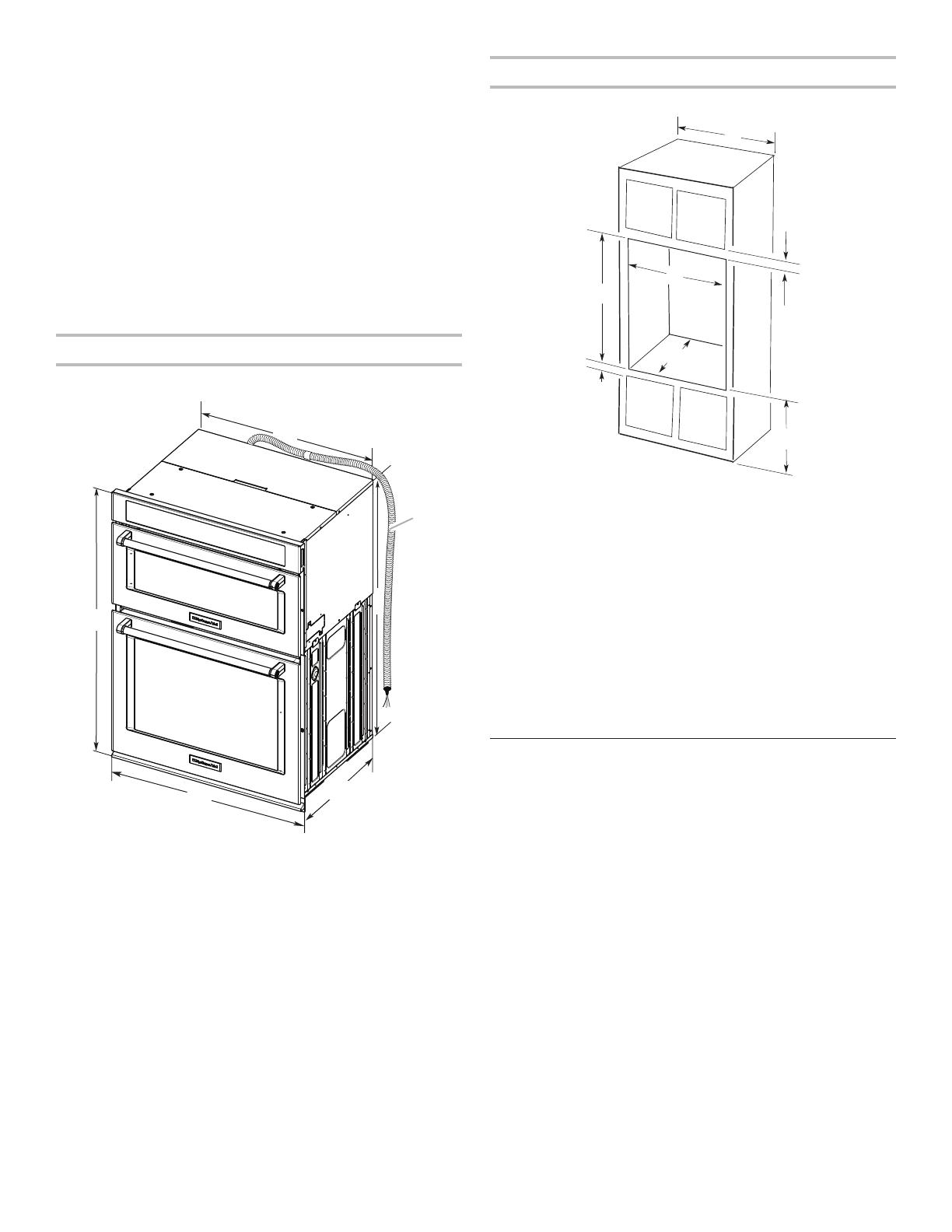
Cabinet Dimensions
27" and 30" (68.6 cm and 76.2 cm) Ovens
* NOTE: The cutout height can be between 41" and 41½"
(104.1 cm and 105.6 cm) for microwave/oven combination.
Electrical Requirements
If codes permit and a separate ground wire is used, it is
recommended that a qualified electrical installer determine
that the ground path and wire gauge are in accordance with
local codes.
Check with a qualified electrical installer if you are not sure the
oven is properly grounded.
This oven must be connected to a grounded metal, permanent
wiring system.
Be sure that the electrical connection and wire size are adequate
and in conformance with the National Electrical Code, ANSI/
NFPA 70-latest edition or CSA Standards C22.1-94, Canadian
Electrical Code, Part 1 and C22.2 No. O-M91-latest edition, and
all local codes and ordinances.
A copy of the above code standards can be obtained from:
National Fire Protection Association
1 Batterymarch Park
Quincy, MA 02169-7471
CSA International
8501 East Pleasant Valley Road
Cleveland, OH 44131-5575
F
E
A
D
G
B
C
27" (68.6 cm) models
A. 27" (68.6 cm) min. cabinet width
B. 1" (2.5 cm) top of cutout to
bottom of upper cabinet door
C. 19
1
/
4
" (48.9 cm) bottom of
cutout to floor is recommended.
4"-19
1
/
4
" (10.2 cm-48.9 cm)
bottom of cutout to floor is
acceptable.
D. 25
1
/
2
" (64.8 cm) cutout width
E. 1
1
/
2
" (3.8 cm) min. bottom of
cutout to top of cabinet door
F. 41
5
/
16
" (105 cm)* recommended
cutout height
G. 24" (60.7 cm) cutout depth
30" (76.2 cm) models
A. 30" (76.2 cm) min. cabinet width
B. 1" (2.5 cm) top of cutout to
bottom of upper cabinet door
C. 19
1
/
4
" (48.9 cm) bottom of
cutout to floor is recommended.
4"-19
1
/
4
" (10.2 cm-48.9 cm)
bottom of cutout to floor is
acceptable.
D. 28
1
/
2
" (72.4 cm) cutout width
E. 1
1
/
2
" (3.8 cm) min. bottom of
cutout to top of cabinet door
F. 41
5
/
16
" (105 cm)* recommended
cutout height
G. 24" (60.7 cm) cutout depth


