Delta T27859 Installation guide

Category
Sanitary ware
Type
Installation guide
MultiChoice
®
Valve Trim with Diverter
Installation Instructions
Owners Manual
T27859, T27867, T27897,
T27899, T27959, T27967,
T27997 & T27999
Series
Write purchased model number here.
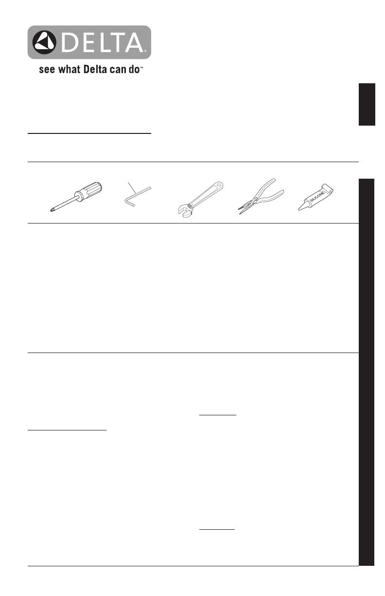
You May Need
THIS VALVE MEETS OR EXCEEDS THE
FOLLOWING STANDARDS: ASME A112.18.1/
CSA B125.1 and ASSE 1016 (Type -P- or -T-).
CAUTION:
This system/device must be set by the
installer to ensure safe, maximum temperature.
Any change in the setting may raise the discharge
temperature above the limit considered safe and
may lead to hot water burns.
NOTICE TO INSTALLER: CAUTION!–As the
installer of this valve, it is your responsibility
to properly INSTALL and ADJUST this valve
per the instructions given. This valve does
not automatically adjust for inlet temperature
changes, therefore, someone must make the
necessary Rotational Limit Stop adjustments
at the time of installation and further adjustments
may be necessary due to seasonal water
temperature change. YOU MUST inform the
owner/user of this requirement by following
the instructions.
If you or the owner/user are
unsure how to properly make these adjustments
please refer to page 6
and if still uncertain, call
us at
1-800-345-DELTA.
After installation and adjustment, you must afx
your name, company name and the date you
adjusted the Rotational Limit Stop to the caution
label provided and apply or attach the label to
the back side of the closest cabinet door and the
warning label to the water heater.
Leave this
Instruction Sheet for the owners/user’s
reference.
WARNING: This pressure balanced or
thermostatic bath valve is designed
to minimize the effects of outlet water
temperature changes due to inlet pressure
changes, commonly caused by dishwashers,
washing machines, toilets and the like. It may
not provide protection from hot water burns
when there is a failure of other temperature
controlling devices elsewhere in the
plumbing system, if the rotational limit stop
is not properly set or if the hot water
temperature is changed after the settings are
made or if the water inlet changes
due to seasonal changes.
WARNING: Do not install a shut-off device on
either outlet of this valve. When this type of
device shuts off the water ow, it can defeat
the ability of the valve to balance the hot and
cold water pressures.
92345 Rev. A1
92345
Table of Contents:
Warranties ...............................................................................  Page 2
Installation Instructions ...........................................................  Pages   3 - 7
Clean and care.........................................................................  Page 9
Maintenance ............................................................................ Page 9
Cartridge Summary Reference Sheet .....................................   Page 9
Classic Series Replacement Parts ..........................................   Page 10-12
For additional replacement parts, visit www.deltafaucet.com
03/06/2017
3/32"
92345 Rev. A
2
Parts and Finish
All parts (other than electronic parts and batteries) and finishes of this Delta
®
faucet are warranted to the original consumer purchaser to be free from
defects in material and workmanship for as long as the original consumer purchaser owns the home in which the faucet was first installed or, for com-
mercial users, for 5 years from the date of purchase.
Electronic Parts and Batteries (if applicable)
Electronic parts (other than batteries), if any, of this Delta
®
faucet are warranted to the original consumer purchaser to be free from defects in material
and workmanship for 5 years from the date of purchase or, for commercial users, for one year from the date of purchase. No warranty is provided on
batteries.
Delta Faucet Company will replace, FREE OF CHARGE, during the applicable warranty period, any part or finish that proves defective in material and/
or workmanship under normal installation, use and service. If repair or replacement is not practical, Delta Faucet Company may elect to refund the
purchase price in exchange for the return of the product. These are your exclusive remedies.
Delta Faucet Company recommends using a professional plumber for all installation and repair. We also recommend that you use only genuine Delta
®
replacement parts.
Delta Faucet Company shall not be liable for any damage to the faucet resulting from misuse, abuse, neglect or improper or incorrectly performed
installation, maintenance or repair, including failure to follow the applicable care and cleaning instructions.
Replacement parts may be obtained by calling the applicable number below or by writing to:
In the United States and Mexico: In Canada:
Delta Faucet Company Masco Canada Limited, Plumbing Group
Product Service Technical Service Centre
55 E. 111th Street 350 South Edgeware Road
Indianapolis, IN 46280 St. Thomas, Ontario, Canada N5P 4L1
1-877-345-DELTA (3358) 1-877-345-DELTA (3358)
Proof of purchase (original sales receipt) from the original purchaser must be made available to Delta Faucet Company for all warranty claims unless
the purchaser has registered the product with Brizo Kitchen & Bath Company. This warranty applies only to Delta
®
faucets manufactured after January
1, 1995 and installed in the United States of America, Canada and Mexico.
DELTA FAUCET COMPANY SHALL NOT BE LIABLE FOR ANY SPECIAL, INCIDENTAL OR CONSEQUENTIAL DAMAGES (INCLUDING LABOR
CHARGES) FOR BREACH OF ANY EXPRESS OR IMPLIED WARRANTY ON THE FAUCET. Some states/provinces do not allow the exclusion or lim-
itation of special, incidental or consequential damages, so these limitations and exclusions may not apply to you. This warranty gives you special legal
rights. You may also have other rights which vary from state/province to state/province.
This is Delta Faucet Company’s exclusive written warranty and the warranty is not transferable.
If you have any questions or concerns regarding our warranty, please view our Warranty FAQs at www.deltafaucet.com, email us at customerservice@
deltafaucet.com or call us at the applicable number above.
Lifetime Faucet and Finish Limited Warranty
© 2017 Masco Corporation of Indiana
92345 Rev. A
Installation
1
Cartridge Installation
A.
B.
Turn off water supplies.
Remove cover (1),
bonnet nuts (2) and test caps (3) from the
rough-in body (4).
Place a bucket or small container over the front
of the valve body and slowly open the water
supplies to ush any debris from the supply
lines before installing the cartridge. Turn the
water supplies back off.
I
nsert adapter assembly (1) into rough-in
body (2). Make sure the adapter assembly
is correctly positioned and is pressed all
the way down inside rough-in body.
Rotate cartridge (1) so the words “HOT SIDE”
(2) appear on the left. Insert cartridge assembly
into rough-in body. Make sure the key (3) on the
valve cartridge is fully engaged with the slot in
the brass body (4). Insert bonnet nut (5) over
the cartridge and thread onto the body. Hand
tighten securely, slide o-ring (6) over bonnet
and cartridge. A light coating of plumbers
grease applied to o-rings may aid in assembly.
For the exceptions of back to back or reverse
installations (hot on right and cold on left) only:
Rotate valve cartridge (1) so “HOT SIDE” (2)
appears on the right.
Apply silicone lube to the three o-rings shown
above to make the cartridge easier to install and
remove from the rough-in body.
Install the cartridge making sure that the keys
are fully engaged with the slot in the rough-in
body (see step C).
Slide o-ring (3) and bonnet nut (4) over the
cartridge and thread onto the rough-in body.
Hand tighten securely.
3
C.
Back to back Installation
Normal Installation
(changes not required)
Reverse
Installation
Cold
Hot
1
2
3
4
2
3
1
2
1
2
3
4
5
3
4
2
4
3
1
6
92345 Rev. A
Installation
2
Diverter Cartridge Installation
4
For Bonnet Installation
Slide bonnet nut (1) over diverter sleeve (2) and
thread into rough-in body.
Hand tighten securely.
B.
FOR DIVERTER CARTRIDGE INSTALLATION:
Apply silicone lube to the o-ring (2) to make
the diverter sleeve (3) easier to install diverter
cartridge.
A light coating of plumbers grease
applied to o-rings (4) may aid in assembly.
Install diverter cartridge (1) assuring that the
locating pin on the bottom of the cartridge
aligns with mating hole in rough-in body.
Slide diverter sleeve (3) over cartridge stem
aligning tabs on the diverter sleeve with slots
in rough-in body (5).
A.
3
1
5
2
1
2
5
4
92345 Rev. A
Installation
3
5
Trim Installation
Trim Sleeve Installation
Slide trim sleeve (1) over the bonnet (2), cartridge
and rough-in body.
Ensure sleeve is properly positioned over the front
of cartridge.
Escutcheon Installation
For nished wall thickness up to 1 1/8". Secure
the backplate (1) to the rough-in body (2) using 4
screws (3) provided.
Note: Be sure backplate is oriented front side
forward and markings are visible.
Slide escutcheon (4) over diverter cartridge, thread
trim nut (5) onto diverter sleeve (6).
Note: For thick wall installations, order
installation kit RP90543 to support nished wall
thickness up to 2 1/8"
.
On rough or uneven surfaces it is necessary to
apply caulk around the backplate (1) to supplement
the seal. Do not caulk the drip notch in the bottom
of the backplate (1). Do not caulk the escutcheon
(4).
1
2
A. B.
1
2
5
4
C.
1
Install volume control handle (1) with lever
pointing down, then turn to the on position.
DO NOT SECURE WITH SCREW.
3
3
6
Drip notch
92345 Rev. A
Installation
4
6
Installation and Adjustment of the Rotational Limit Stop
A.
B.
Place the rotational limit stop (1) in
volume
handle (2) and rotate to the mixed
position (if
required). DO NOT SECURE WITH
SCREW.
Turn on water supplies; let the
water
run until
both hot and cold water is as hot/
cold as
possible. Place thermometer in a plastic tumbler,
and hold the tumbler in the water stream.
Record the temperature reading.
If the water temperature is above 120°F, remove
and rotate the limit stop (1) clockwise one tooth
for every 4°F - 6°F (approximate) change in
temperature. If water temperature is cooler than
desired, rotate the limit stop counterclockwise.
IMPORTANT:
The rst position of the Rotational
Limit Stop (the Limiter) is the position that
restricts the rotation of the stem the most and is
at the maximum clockwise setting. According to
industry standards, the maximum allowable
temperature of the water exiting from the valve
is 120
o
F. This temperature may vary in your local
area. The Rotational Limit Stop may need to be
readjusted if the inlet water temperature changes.
For instance, during the winter, the cold water
temperature is colder than it is during the summer
which could result in varying outlet temperatures.
Typical temperature for a comfortable bath or
shower is between 90
o
–110
o
F.
5
Potential scald or thermal shock injury could result due to cross ow if outlet at the shower is
blocked or restricted (e.g., pause control on showerhead). Be sure to point showerhead away
from you when re-starting ow or install inlet check valves on both supply lines to prevent
possible injury.
C.
Hotter
Colder
Secure temperature control knob (1) with
screw (2). Snap on temperature control cover
(3) with side snaps onto knob (1).
1
1
1
2
3
2
92345 Rev. A7
6
Diverter handle Installation
Installation
B.
2
1
3
Diverter Handle Installation
Slide diverter handle (1) onto trim sleeve (2).
Using a allen wrench, insert set screw (3) into
handle (1). Applying pressure, insert set screw
cover (4) until properly seated.
4
92345 Rev. A
Clean and Care
Care should be given to the cleaning
of this product. Although its nish is
extremely durable, it can be damaged by
harsh abrasives or polish. To clean, simply
wipe gently with a damp cloth and blot dry
with a soft towel.
Maintenance
Faucet leaks from showerhead:
SHUT OFF WATER SUPPLIES.
Replace valve cartridge
RP46463 or RP32104
See Helpful Hints 1, 2, 3 & 4.
Helpful Hints:
1. Before removing valve cartridge assembly for any
maintenance, be sure to note the position of the
rotational limit stop on the cap. The valve cartridge
assembly must always be put back in the same
position. BE SAFE! After you have nished the
installation, turn on valve to make sure COLD
WATER FLOWS FIRST.
2. To remove valve cartridge from body, shut off
water supplies and remove handle and bonnet nut.
Do not pry the valve cartridge out of the body with
a screwdriver. Place handle on stem and rotate
counterclockwise approximately 1/4 turn after the
stop has been contacted. Lift valve cartridge out
of body.
Remove seats and springs and replace.
Place the largest diameter of the spring into the
seat pocket rst and then press the tapered end
of the seal over the spring. Reassemble valve
cartridge and replace in body following instructions
given in 1 above.
3. If the water in your area has lime, rust, sand
or other contaminants in it, your pressure
balance valve will require periodic inspection.
The frequency of the inspection will depend
on the amount of contaminants in the water. To
inspect valve cartridge remove it and follow the
steps in note 1 above. Turn the valve to the full
mix position and shake the cartridge vigorously.
If there is a rattling sound, the unit is functional
and can be reinstalled following instructions given
in note 1 above. If there is no rattle, replace the
housing assembly with the proper RP.
Cartridge Summary Reference Sheet
Order RP46463 to
Replace Cartridge.
Grey Upper Cap
V Notch
Adapter
Shorter Tab
T27
9
92345 Rev. A
Delta Faucet Company
Product Service
55 E. 111th Street
Indianapolis, IN 46280
1 / 1

Delta T27859 Installation guide

Category
Sanitary ware
Type
Installation guide

Ask a question and I''ll find the answer in the document

Finding information in a document is now easier with AI

Ask the document