KitchenAid KEHS01P Owner's manual

Category
Washer dryers
Type
Owner's manual
KitchenAid ®
FRONT-LOADING ELECTRIC DRYER
Use & Care Guide
For questions about features, operation/performance, parts accessories or service, call: 1-800-422-1230
In Canada, call for assistance 1-800-461-5681, for installation and service, call: 1-800-807-6777 or visit our website at...
www.kitchenaid.com or www.KitchenAid.ca
SECADORA ELI_CIRICA DE CARGA FRONTAL
Manual de Uso y Cuidado
Si tiene preguntas respecto a las caractertsticas, funcionamiento/rendimiento, partes, accesorios o servicio t6cnico, Ilame al: 1-800-422-1230
Para la instalaci6n y el servicio t6cnico Ilame al: 1-800-807-6777 o visite nuestro sitio web en... www.kitchenaid.com
S]_CHEUSE ]_LECIRIQUE )_ CHARGEMENT
)_ L'AVANT
Guide d'utilisation et d'entretien
Au Canada, pour assistance composez le 1-800-461-5681, pour installation ou service composez le 1-800-807-6777
ou visitez notre site web 6... www.KitchenAid.ca
Table of Contents/[ndice/Table des mati6res ............................................................... 2-3
Models/Modelos/Mod_les KEHS01 P, YKEHS01 P
8557328A
TABLEOF CONTENTS
DRYER SAFETY ...................................................... 4
INSTALLATION INSTRUCTIONS ................................... 5
Tools and Parts ............................................................................ 5
Options ............................................................. 5
Location Requirements ............................................................... 5
Electrical Requirements- U.S.A. Only........................................ 7
Electrical Requirements - Canada Only... ................................... 8
ElectricalConnection - U.S.A. Only............................................. 9
Venting Requirements ............................................. 13
PlanVent System .................................................. 14
InstallVent System ................................................. 15
Install Leveling Legs............................................... 15
Level Dryer ......................................................... 16
Connect Vent...................................................... 16
Reverse Door Swing .............................................. 16
Complete Installation ............................................. 17
DRYER USE ......................................................... 18
Starting Your Dryer................................................. 18
Stopping Your Dryer .............................................. 19
Pausing or Restarting............................................. lg
Control Locked. ................................................... 19
Loading............................................................. 19
Drying and Cycle Tips ............................................. 19
Status Lights .............................................................................. 20
Cycles ............................................................. 20
Additional Features ............................................... .21
Drying Rack ....................................................... .22
DRYER CARE ...................................................... 23
Cleaning the Dryer Location ..................................... .23
Cleaning the Lint Screen .......................................... 23
Cleaning the Dryer Interior ........................................ 23
Removing Accumulated Lint..................................... .23
Vacation and Moving Care......................................................... 23
Changing the Drum LighL......................................................... 24
TROUBLESHOOTING .............................................. 24
ASSISTANCE OR SERVICE ......................................................... 25
Inthe U.S.A. ....................................................... 25
In Canada ......................................................... .25
WARRAN'rY ......................................................... 26
INDICE
BEGURIDAD DE LA SECADORA .................................. 27
INSTRUCCIONEB DE INBTALACION ............................. 28
Herramientes y piezes ............................................ .28
Opciones .......................................................... .28
Requisitos de ubicacibn .......................................... .28
Requisitos el6ctricos - EE. UU. ................................... .30
Conexibn al6ctrica - Sblo en EE. UU. ........................... .32
Requisitos de ventilacibn ......................................... .36
Planificaci6n del alstema de ventilacibn ................................... .36
Instalaci6n del alstema de ventilaci6n ....................................... 38
Instalaci6n de les pates nivaladores......................................... .38
Nivelaci6n de laescadora ........................................ .39
Conexibn dal ducto de escape ................................... .39
Cbmo invertir el cierre de la puerta............................... .39
Complete la instalacibn........................................... .40
UBO DE LA BECADORA ............................................ 41
Puesta en marcha de la secadora ............................... _41
Detenci6n de la marcha de laescadora ................................... _42
Pausa o resnudaci6n de la marcha .............................. _42
Control bloquesdo ............................................... _42
Cbmo cargar ....................................................... A2
Sugerencies de ciclos ysecado .................................. _42
Luces de estado .................................................... 43
Ciclos. ........................................................................................ _43
Caracter[sticas adicionales ....................................... _44
Estante de secado. ................................................ _45
CUIDADO DE LA SECADORA ..................................... 46
Limpieza del lugardonde est& la escadora .............................. _46
Limpieza del filtro de palusa ...................................... _46
Limpieza del interiorde la escadora ............................. _47
Eliminacibn de pelues acumulada ............................... _47
Cuidado para lesvacaciones y la mudanza ............................. A7
Cembio de la luz dal tambor ..................................... _47
SOLUCION DE PROBLEMAB ...................................... 48
AYUDA O SERVlCIO TECNICO ................................................... 49
GARANT[A. .......................................................... 50
2
DRYER SAFETY
Your safety and the safety of others are very important.
We have provided many important safety messages in this manual and on your appliance. Always read and obey all safety
messages.
This is the safety alert symbol.
This symbol alerts you to potential hazards that can kill or hurt you and others.
All safety messages will follow the safety alert symbol and either the word "DANGER" or "WARNING."
These words mean:
You can be killed or serlousty Injured If you don't Immedlatel_
follow Instructions.
You can be killed or seriously Injured If you don't follow
Instructions.
All safety messages will tell you what the potential hazard is, tell you how to reduce the chance of injury, and tell you what can
happen if the instructions are notfollowed.
IMPORTANT SAFETY INSTRUCTIONS
WARNING: To reducethe riskoffire,electricshock,or injuryto personswhen usingthe dryer,follow basicprecautions,
including the following:
Read all instructions before using the dryer.
Do not place items exposed to cooking oils in your dryer.
Items contaminated with cooking oils may contribute to
a chemical reaction that could cause a load to catch fire.
Do not dry articles that have been previously cleaned in,
washed in, soaked in, or spotted with gasoline, dry-
cleaning solvents, other flammable, or explosive
substances as they give off vapors that could ignite or
explode.
Do not allow children to play on or in the dryer. Close
supervision of children is necessary when the dryer is
used near children.
Before the dryer is removed from service or discarded,
remove the door to the drying compartment.
Do not reach into the dryer ifthe drum ismoving.
Do not install or store the dryer where it will be exposed
to the weather.
Do not tamper with controls.
Do not repair or replace any part of the dryer or attempt
any servicing unless specifically recommended in this
Use and Care Guide or in published user-repair
instructions that you understand and have the skills to
carry out.
Do not use fabric eoftaners or products to eliminate static
unless recommended by the manufacturer of the fabric
softener or product.
Do not use heat to dry articles containing foam rubber or
similarly textured rubber-like materials.
Clean lint screen before or after each load.
Keep area around the exhaust opening and adjacent
surrounding areas free from the accumulation of lint, dust,
and dirt.
The interior of the dryer and exhaust vent should be
cleaned periodically by qualified service personnel.
See installation instructions for grounding requirements.
SAVE THESE INSTRUCTIONS
4
INSTALLATION INSTRUCTIONS
Tools and Parts
Gather the required tools and parts before starting installation.
Read and follow the safety instructions provided with any tools
listed here.
a
a
a
a
Flat-blade screwdriver
Adjustable wrench that
opens to 1" (2.5 cm) or
hex-head socket wrench
(for adjusting dryer feet)
Level
Wire stripper (direct wire
installations)
= #2 Phillips screwdriver
a Vent clamps
a Caulking gun and
compound (for installing
new exhaust vent)
a Tin snips (new vent
installations)
= 1A"nut driver
Op_on8
Pedestal
Are you placing the dryer on a pedestal? You may purchase a
pedestal separately for this dryer. This pedestal will add about
13" (33 cm) to the height of your unit for a total height of
approximately 51" (130 cm).
Parts supplied
Remove parts packages from dryer drum. Check that all parts are
included.
4 Levelinglegs
NOTE: Do not use leveling legs if installingthe dryer on a
pedestal.
Parts needed
Check local codes. Check existing electrical supply and venting.
See "Electrical Requirements" and "Venting Requirements"
before purchasing parts.
a For close-clearance installations between 31.5" (80.01 am)
and 37" (93.98 ca), see "Plan Vent System" section for
venting requirements.
I_ 37" _,-I
(93.98 cm)
Mobile home installations require metal exhaust system hardware
available for purchase from the dealer from whom you purchased
your dryer. Forfurther information, please referto the "Assistance
or Service" section of this manual.
Optional pedestal
To order, call the dealer from whom you purchased your dryer or
refer to the "Assistance or Service" section of this manual. Ask
for Part Number LAB270OPMT (Meteorite) or LAB2700MQO
(White).
Stack lot
Are you planning to stack your washer and dryer? To do so, you
will need to purchase a Stack Kit.
To order, call the dealer from whom you purchased your dryer or
refer to the "Assistance or Service" section of this manual. Ask
for Part Number 8541503.
Location Requirements
Explosion Hazard
Keep flammable materials and vapors, such as
gasoline, away from dryer,
Place dryer at least 18 Inches (46 cm) above the floor
for a garage Inafallatlon,
Fallura to do so can result In death, explosion, or firs,
You will need
m A location that allows for proper exhaust installation. See
"Venting Requirements."
m A separate 30 amp circuit.
m A grounded electrical outlet located within 2 ft (61 cm) of
either side of the dryer. Sea "Electrical Requirements."
= A sturdy floor to support the total dryer weight of
200 Ibs (90.7 kg). The combined weight of a companion
appliance should also be considered.
= A level floor with a maximum slope of 1" (2.5 cm) under entire
dryer. If slope is greater than 1" (2.5 cm), install Extended
Dryer Feet Kit, Part Number 279810. Clothes may not tumble
properly and automatic sensor cycles may not operate
correctly if dryer is not level.
= For a garage installation, you will need to place the dryer at
least 18" (46 cm) above the floor. If using a pedestal, you will
need an additional 6" (15.24 cm).
Do not operate your dryer at temperatures below 45°F (7°C). At
lower temperatures, the dryer might not shut off at the end of an
automatic cycle. This can result in longer drying times.
The dryer must not be installed or stored in an area where it will
be exposed to water and/or weather.
Check code requirements. Some codes limit, or do not permit,
installation ofthe dryer in garages, closets, mobile homes, or
sleeping quarters. Contact your local building inspector.
Installation clearances
a The location must be large enough to fully open the dryer
door.
a Additional spacing should be considered for ease of
installation and servicing.
a Additional clearances might be required for wall, door and
floor moldings.
a Additional spacing of 1" (2.5 ore) on all sides of the dryer is
recommended to reduce noise transfer.
a Companion appliance spacing should also be considered.
Dryer Dimensions
(130,81 cm)
(96.52 cm)
"31½"
(80 cm) 27"
.._-_ (68.6 cm)
* 4 "
Most installations require a minimum (14 cm) clearance
behind the dryer for the exhaust vent with elbow. See "Venting
Requirements."
Minimum installation spacing for custom undercounter
installation
The dimensions shown are for the minimum spacing allowed.
Custom undercounter installation - Dryer only
00ml I
3B" min.
(96.52 cm)
O" 27" O"
(Ocm)'-_(6B.8 cm)-_(O cm)
Minimum installation spacing for recessed or closet
installation, with or without a pedestal
a The dimensionsshownareforthe minimumspacingallowed,
a
For closet installation, with a door, minimum ventilation
openings in the top and bottom of the door are required.
Louvered doors with equivalent ventilation openings are
acceptable.
Closet installation - Dryer only
1o,,l_31½,,_1o"l
(0 cm) (B0 cm) (Ocm)
A
48 In.2
(310cm:Z)-
24 In.2
(155 cm:Z)-
B
3"
_(7.6 cm)
3"
_- (7.6 cm)
A. Side view - closet or confined area
B. Closet door with vents
Recessed or closet installation - Dryer on pedestal
o" -_ _-- 27" "--_ <-o" o,,II_- 31½"-_1o"I
(0 cm) (68.6 cm) (O cm) (Ocm) (90 cm) (0 cm)
A B
A. Recessed area
B. Side view - closet or confined area
6
Minimuminstallationspacingforcabinetinstallation
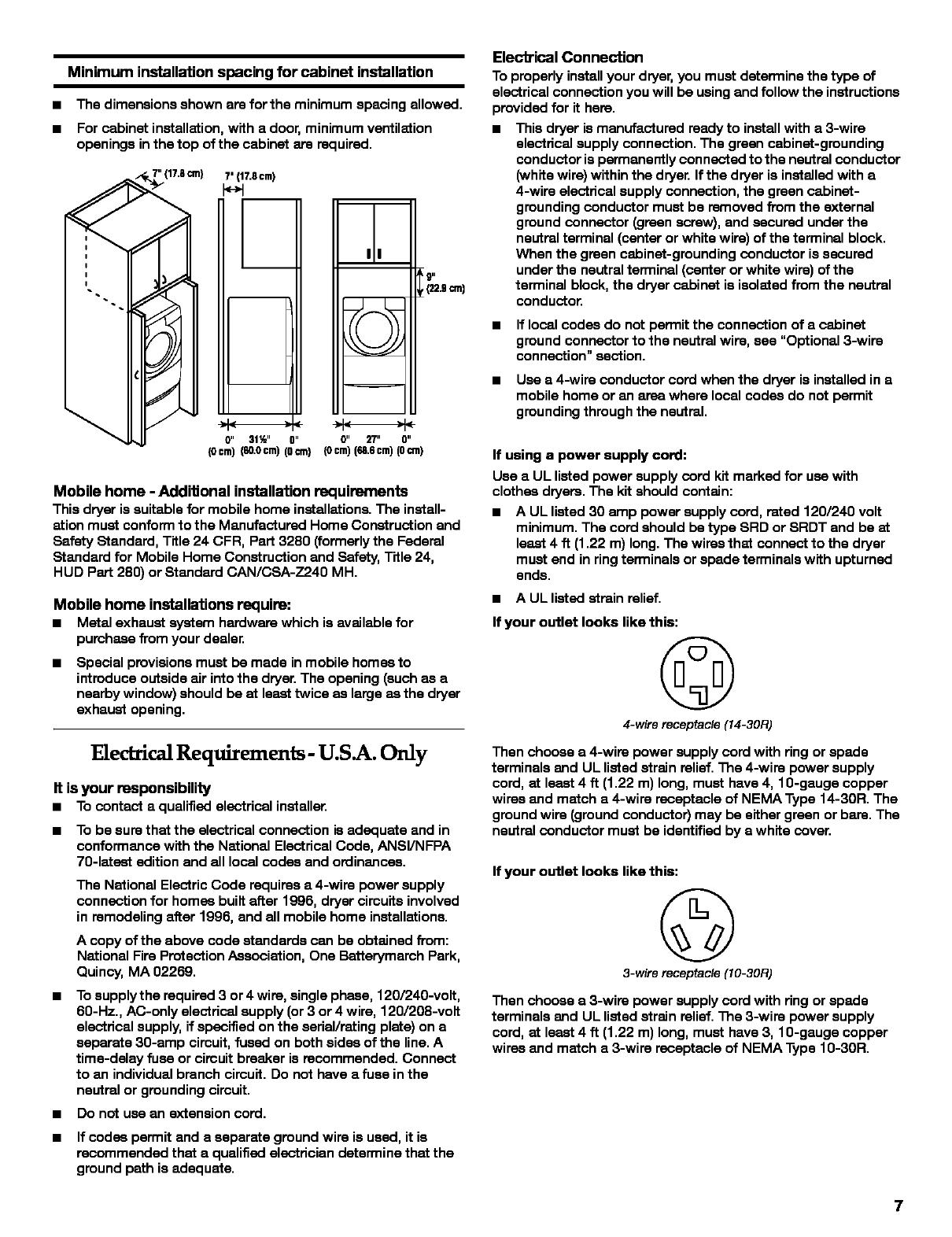
a The dimensions shown are for the minimum spacing allowed.
a For cabinet installation, with a door, minimum ventilation
openings in the top of the cabinet are required.
7' {17,8cm)
0" 31½" 0" 0" _" 0"
(0cm)(s0.0cm)(0cm) (0cm)(=.scm)(0cm)
9,,
,(22.gcm)
Mobile home -Additional installation requirements
This dryer issuitable for mobile home installations. The install-
ation must conform to the Manufactured Home Construction and
Safety Standard, Title 24 CFR, Part 3280 (formerly the Federal
Standard for Mobile Home Construction and Safety, Title 24,
HUD Part 280) or Standard CAN/CSA-Z240 MH.
Mobile home installations require:
m Metal exhaust system hardware which is available for
purchase from your dealer.
a
Special provisions must be made in mobile homes to
introduce outside air into the dryer. The opening (such as a
nearby window) should be at least twice as large as the dryer
exhaust opening.
ElectricalRequirements- U.S.A. Only
It isyour responsibility
m Tocontacta qualifiedelectricalinstaller,
m To be sure that the electrical connection isadequate and in
conformance with the National Electrical Code, ANSI/NFPA
70-1etast edition and all local codas and ordinances.
The National Electric Code requires a 4-wire power supply
connection for homes built after 1996, dryer circuits involved
in remodeling after 1996, and all mobile home installations.
A copy of the above code standards can be obtained from:
National Fire Protection Association, One Betterymarch Park,
Quincy, MA 02269.
m To supply the required 3 or 4 wire, single phase, 120/240-volt,
60-Hz., AC-only electrical supply (or 3 or 4 wire, 120/208-volt
electrical supply, if specified on the serial/rating plate) on a
separate 30-amp circuit, fused on both sides of the line. A
time-delay fuse or circuit breaker is recommended. Connect
to an individual branch circuit. Do not have a fuse in the
neutral or grounding circuit.
m Do net use an extension cord.
m If codas permit and a separate ground wire is used, it is
recommended that a qualified electrician determine that the
ground path is adequate.
Electrical Connection
To properly install your dryer, you must determine the type of
electrical connection you will be using and follow the instructions
provided for it here.
a This dryer is manufactured ready to install with a 3-wire
electrical supply connection. The green cabinet-grcunding
conductor ispermanently connected to the neutral conductor
(white wire) within the dryer. If the dryer is installed with a
4-wire electrical supply connection, the green cabinet-
grounding conductor must be removed from the external
ground connector (green screw), and secured under the
neutral terminal (center or white wire) of the terminal block.
When the green cabinet-grounding conductor is secured
under the neutral terminal (center or white wire) of the
terminal block, the dryer cabinet is isolated from the neutral
conductor.
m If local codas do not permit the connection of a cabinet
ground connector to the neutral wire, see "Optional 3-wire
connection" section.
m Use a 4-wire conductor cord when the dryer is installed in a
mobile home or an area where local codas do not permit
grounding through the neutral.
If using a power supply cord:
Use a UL listed power supply cord kit marked for use with
clothes dryers. The kit should contain:
a A UL listed 30 amp power supply cord, rated 120/240 volt
minimum. The cord should be type SRD or SRDT and be at
least 4 ft (1.22 m) long. The wires that connect to the dryer
must end in ring terminals or spade terminals with upturned
ends.
a A UL listed strain relief.
If your outlet looks like this:
©
4-wire receptacle(14-30R)
Then choose a 4-wire power supply cord with ring or spade
terminals and UL listed strain relief. The 4-wire power supply
cord, at least 4 ft (1.22 m) long, must have 4, 10-gauge copper
wires and match a 4-wire receptacle of NEMA Type 14-30R. The
ground wire (ground conductor) may be either green or bare. The
neutral conductor must be identified by a white cover.
If your outlet looks like this:
©
3-wire receptacle(10-30R)
Then choose a 3-wire power supply cord with ring or spade
terminals and UL listed strain relief. The 3-wire power supply
cord, at least 4 ft (1.22 m) long, must have 3, 10-gauge copper
wires and match a 3-wire receptacle of NEMA Type 10-30R.
7
If connecting by direct wire:
Power supply cable must match power supply (4-wire or 3-wire)
and be:
a Flexible armored cable or nonmetallic sheathed copper cable
(with ground wire), protected with flexible metallic conduit. All
current-carrying wires must be insulated.
= 10-gauge solid copper wire (do not use aluminum).
= At least 5 ft (1.52 m) long.
GROUNDING INSTRUCTIONS
= Fora grounded, cord-connected dryer:
This dryer must be grounded. In the event of malfunction or
breakdown, grounding will reduce the risk of electric shock
by providing a path of least resistance for electric current.
This dryer uses a cord having an equipment-grounding
conductor and a grounding plug. The plug must be plugged
intoan appropriate outlet that is properly installed and
grounded in accordance with all local codes and ordinances.
= Fora permanently connected dryer:
This dryer must be connected to a grounded metal,
permanent wiring system, or an equipment-greunding
conductor must be run with the circuit conductors and
connected to the equipment-grounding terminal or lead on
the dryer.
WARNING: Improper connection of the equipment-
grounding conductor can result in a risk of electric shock.
Check with a qualified electrician or service representative
or personnel if you are in doubt as to whether the dryer is
properly grounded. Do not modify the plug on the power
supply cord: if it will not fit the outlet, have a proper outlet
installed by a qualified electrician.
SAVE THESE INSTRUCTIONS
Electrical Requirements- Canada Only
Electrical Shock Hazard
Plug Into a grounded 4 prong outlet.
Failure to do so can result In death or electrical shock.
m TOsupply the required 4 wire, single phase, 115/230-volt,
6O-Hz., AC-only electrical supply on a separate 30-arnp
circuit, fused on both sides ofthe line. A time-delay fuse or
circuit breaker is recommended. Connect to an individual
branch circuit.
= This dryer is equipped with a CSA International Certified
Power Cord intended to be plugged into a standard 14-30R
wall receptacle. The cord is5 fc(1.52 m) in length. Be sure
wall receptacle is within reach of dryer's final location.
©
4-wire receptacle 14-30R
= Do nat use an extension cord.
If using a replacement power supply cord, it is recommended
that you use Power Supply Cord Replacement Part Number
9831317. Forfurther information, please reference the service
numbers located inthe "Assistance or Service" section on this
manual.
GROUNDING INSTRUCTIONS
= Fora grounded, cord-connected dryer:
This dryer must be grounded. In the event of malfunction or
breakdown, grounding will reduce the risk of electric shock
by providing a path of least resistance for electric current.
This dryer is equipped with a cord having an equipment-
grounding conductor and a grounding plug.The plug must
be plugged into an appropriate outlet that is properly
installed and grounded in accordance with all local codes
and ordinances.
WARNING: Improper connection of the equipment-
grounding conductor can result in a risk of electric shock.
Check with a qualified electrician or service representative
or personnel if you are in doubt as to whether the dryer is
properly grounded. Do not modify the plug provided with the
dryer: if itwill not fitthe outlet, have a proper outlet installed
by a qualified electrician.
SAVE THESE INSTRUCTIONS
It isyour responsibility
a Tocontacta qualifiedelectricalinstaller,
m To be sure that the electrical connection isadequate and in
conformance with the Canadian Electrical Code, C22.1-1atest
edition and all local codes. A copy ofthe above codes
standard may be obtained from: Canadian Standards
Association, 178 Rexdale Blvd., Toronto, ON Mgw 1R3
CANADA.
8
PowerSupplyCord
Electrical Connection- U.S.A. Only
Direct Wire
Fire Hazard
Use a new UL listed 30 amp power supply cord.
Use a UL listed strain relief.
Disconnect power before making electrical connections.
Connect neutral wire (white or center wire) to center
terminal (sliver).
Ground wire (green or bare wire) must be connected to
green ground connector.
Connect remaining 2 supply wires to remaining
2 terminals (gold).
Securely tighten all electrical connections.
Failure to do so can result In death, fire, or
electrical shock.
Fire Hazard
Use 10 gauge solid copper wire.
Use a UL listed strain relief.
Disconnect power before making electrical connections.
Connect neutral wire (white or center wire) to center
terminal (sliver).
Ground wire (green or bare wire) must be connected to
green ground connector.
Connect remaining 2 supply wires to remaining
2 terminals (gold).
Securely tighten all electrical connections.
Failure to do so can result In death, fire, or
electrical shock.
1. Disconnect power.
2. Remove the hold-down screw and terminal block cover.
D
A. Neutral grounding wire (green with yellow stdpes)
B. External ground conductor screw
C. Center, silver-colored terminal block scraw
D. Terminal block cover and hold-down screw
3.
4.
Assemble a ¾" (1.9 cm) UL listed strain relief (UL marking on
strain relief) into the hole below the terminal block opening.
Tighten strain relief screws just enough to hold the two clamp
sections together. Put power supply cord through the strain
relief. The strain relief should have a tight fit with the dryer
cabinet and be in a horizontal position.
Now complete installation following instructions for your type
of electrical connection:
4-wire (recommended)
3-wire (if4-wire is not available)
Electrical Connection Options
If your homo has: And you will be Go to Section
connecting to:
4-wire receptacle A UL listed,
(NEMA Type 14-30R) 120/240 volt
minimum,
30 amp, dryer
power supply
cord*
4-wire connection:
Power supply cord
4-wire direct A fused 4-wire connection:
disconnect or Direct Wire
circuit breaker
box*
B-wire receptacle A UL listed, B-wire connection:
(NEMA type 10-3OR) 120/240 volt Power supply cord
minimum,
30 amp, dryer
power supply
COrd*
B-wire direct A fused B-wire connection:
disconnect or Direct Wire
circuit breaker
box*
*If local codes do not permit the connection of a frame-grounding
conductor to the neutral wire, go to "Optional
B-wire Connection" section.
4-wire connection: Power supply cord
IMPORTANT: A 4-wire connection is required for mobile homes
and where local codes do not permit the use of B-wire
connections.
C D E G
A.4-wire receptacle(NEMAtype 14-30R)
B.4-prong plug
C.Ground prong
D.Neutralprong
E.Spade terminalswith upturnedends
K _" (1.9cm) ULlisted strainrelief
G.Ring terminals
1.
2.
Remove center terminal block screw.
Remove neutral grounding wire (green with yellow stripes)
from external ground conductor screw. Fasten itunder center,
silver-colored terminal block screw.
A
C
A. External ground conductor screw - Dotted line shows
position of NEUTRAL grounding wire before being
moved to center terminal block screw
B. Center silver-colored terminal block screw
C. Green/yallow wire of harness
3. Connect ground wire (green or bare) of power supply cord to
external ground conductor screw. Tighten screw.
4. Connect neutral wire (white or center wire) of power supply
cord under center screw of the terminal block.
B
C
A. External ground conductor screw
B. Ground wire (green or bare) wire of power supply cord
C. _" (1.9 cm) UL listed strain relief
D. Center silver-colored terminal block screw
E. Neutral grounding wire (green with yellow stripes)
K Neutral wire (white or center wire)
5. Connect the other wires to outer terminal block screws.
Tighten screws.
6. Tighten strain reliefecrews.
7. Insert tab ofterminal block cover into slot of dryer rear panel.
Secure cover with hold-down screw.
10
3. Connect ground wire (green or bare) of power supply cable to
4-wire connection: Direct wire external ground conductor screw. Tighten screw.
IMPORTANT: A 4-wire connection is required for mobile homes
and where local codes do not permit the use of 3-wire
connections.
Direct wire cable must have 5 ft (1.52 m) of extra length so dryer
can be moved if needed.
Strip 5" (12.7 on) of outer covering from end of cable, leaving
bare ground wire at 5" (12.7 cm). Cut 11,_'' (3.8 cro) from 3
remaining wires. Strip insulation back 1" (2.5 cm). Shape ends of
wires into a hook shape.
When connecting to the terminal block, place the hooked end of
the wire under the screw of the terminal block (hook facing right),
squeeze hooked end together and tighten screw. See example
below.
1,
2.
Remove center terminal block screw.
Remove neutral grounding wire (green with yellow stripes)
from external ground conductor screw. Fasten itunder center,
silver-colored terminal block screw.
A
\
C
B
C
F
A. External ground conductor screw
B. Green or bare copper wire of power supply cable
C. ¾" (1.9 cm) UL /isted straln relief
D. Center silver-colored terminal block screw
E. Neutral grounding wire (green with yellow stripes)
I_ Neutral wire (white or center wire)
4. Piece the hooked end of the neutral wire (white wire) of power
supply cable under the center screw of terminal block (hook
facing right). Squeeze hooked end together. Tighten screw.
5. Place the hooked ends of the other power supply cable wires
under the outer terminal block screws (hooks facing right).
Squeeze hooked ends together. Tighten screws.
II
6. Tighten strain relief screws.
7. Insert tab ofterminal block cover into slot of dryer rear panel.
Secure cover with hold-down screw.
A. External ground conductor screw - Dotted line shows
position of NEUTRAL grounding wire before being
moved to center terminal block screw
B. Center silver-colored terminal block screw
C. Green/yallow wire of harness
11
3-wire connection: Power supply cord 3-wire connection: Direct wire
Use where local codes permit connecting cabinet-ground
conductor to neutral wire.
C G F
1.
2.
A. 3-wire receptacle (NEMA type I0-30R)
B. 3-wire plug
C. Neutral prong
D. Spade terminals with up turned ends
E. _" (1.9 cm) UL listed strain relief
K Ring terminals
G. Neu_'al (white or center wire)
Loosen or remove center terminal block screw.
Connect neutral wire (white or center wire) of power supply
cord to the center, allver-colored terminal screw of the
terminal block. Tighten screw.
B
E
Use where local codes permit connecting cabinet-ground
conductor to neutral wire.
Direct wire cable must have 5 ft (1.52 m) of extra length so dryer
can be moved if needed.
Strip 3W' (8.9 cm) of outer covering from end of cable. Strip
insulation back 1" (2.5 cm). If using 3-wire cable with ground
wire, cut bare wire even with outer covering. Shape ends of wires
into a hook shape.
When connecting to the terminal block, place the hooked end of
the wire under the screw of the terminal block (hook facing right),
squeeze hooked end together and tighten screw. See example
below.
1.
2.
Loosen or remove center terminal block screw.
Place the hooked end ofthe neutral wire (white or center wire)
of power supply cable under the center screw ofterminal
block (hook facing right). Squeeze hooked end together.
Tighten screw.
A. External ground conductor screw
B. Neutral grounding wire (green with yellow stripes)
C. Center allver-colored terminal block screw
D. Neutral wire (white or center wire)
E. _" (1.9 crn) UL listed strain relief
3. Connect the other wires to outer terminal block screws.
Tighten screws.
4. Tighten strain relief screws.
5. Insert tab of terminal block cover into slot of dryer rear panel.
Secure cover with hold-down screw.
3.
B
-D
E
A. E_temal ground conductor screw
B. Neutral grounding wire (green with yellow stripes)
C. Center silver-colored terminal block screw
D. Neural wire (white or center wire)
E. ¾" (1.9 cm) UL listed strain relief
Place the hooked ends of the other power supply cable wires
under the outer terminal block screws (hooks facing right).
Squeeze hooked ends together. Tighten screws.
I !
4. Tighten strain relief screws.
5. Insert tab ofterminal block cover into slot of dryer rear panel.
Secure cover with hold-down screw.
12
Optional 3-wire connection Venting Requirements
Use for direct wire or power supply cord where local codes
do not permit connecting cabinot-ground conductor to
neutral wire.
1. Remove center terminal block screw.
2. Remove neutral grounding wire (green with yellow stripes)
from external ground conductor screw. Connect appliance
ground wire and the neutral wire (white or center wire) of
power supply cord/cable under center, silver-colorad terminal
block screw. Tighten screw.
3. Connect the other wires to outer terminal block screws.
Tighten screws.
I !
4. Tighten strain relief screws.
5. Insert tab of terminal block cover into slot of dryer rear panel.
Secure cover with hold-down screw.
6. Connect a separate copper ground wire from the external
ground conductor screw to an adequate ground.
A
D
Fire Hazard
Use a heavy metal vent.
Do not use a plaatlc vent.
Do not use a metal foil vent.
Failure to follow these Inatructlons can result In death
or fire.
WARNING: To reduce the risk of fire, this dryer MUST BE
EXHAUSTED OUTDOORS.
4" (10.2 cm) heavy metal exhaust vent and clamps must be used.
DURASAFE TM vent products are recommended.
DURASAFE TM vent products can be purchased from your dealer
or by calling Whirlpool Parts and Accessories. For more
information, see the "Assistance or Service" section ofthis
manual.
The dryer exhaust must not be connected into any gas vent,
chimney, wall, ceiling, or a concealed space of a building.
Do not use an exhaust hood with a magnetic latch.
Do not install flexible metal vent in enclosed walls, ceilings or
floors.
Use clamps to seal all joints. Exhaust vent must not be
connected or secured with screws or other fastening devices
which extend into the interior of the duct. Do not use duct
tape.
IMPORTANT: Observe all governing codes and ordinances.
.__---
A. External ground conductor screw
B. Neutral grounding wire (green with yellow stripes)
C. Neutral wire (white or center wire)
D. Grounding path determined by a qualified electrfcian
Improper venting can cause moisture and lint to collect
Indoors, which may result In:
Moisture damage to woodwork, furniture, paint,
wallpaper, carpets, etc.
Housecleaning problems and health problems.
Use a heavy metal vent. Do not use plastic or metal foil vent.
Rigid metal vent is recommended to prevent crushing and
kinking.
Flexible metal vent must be fully extended and supported when
the dryer isin its final position. Remove excess flexible metal vent
to avoid sagging and kinking that can result in reduced airflow
and poor performance.
An exhaust hood should cap the vent to prevent rodents and
insects from entering the home.
Exhaust hood must be at least 12" (30.5 cm) from the ground or
any object that is in the path ofthe exhaust (such as flowers,
rocks or bushes, etc.).
If using an existing vent system, clean lint from the entire length
of the system and make sure exhaust hood is not plugged with
lint. Replace any plastic or metal foil vent with rigid metal or
flexible metal vent.
13
Plan Vent System
Typical exhaust installations
Typical installations vent the dryer from the rear of the dryer.
Other installstions are possible.
A. Dryer
B. Elbow
C. Wall
D. Exhaust hood
A m
B
_H
E. Clamps
E Rigid metal or flexible metal vent
G. Vent length necessary to connect elbows
H. Exhaust outlet
Optional exhaust installations
This dryer can be converted to exhaust out the right side, left
side, orthrough the bottom. Contact your local dealer to have the
dryer converted.
Fire Hazard
Cover unused exhaust holes with one of the
following kits:
279818 (white)
280028 (meteorite)
Contact your local dealer.
Failure to follow these Inatructlons can result In death,
fire, electrical shock, or serious Injury.
Alternate installations for close clearances
Venting systems come in many varietiea. Select the type beat for
your installation. Two close-clearance installations are shown.
Refer to the manufacturer's instructions.
ii I i _1
", J
A B
A. Over the top installation (also available with one
offset elbow)
B. Periscope installation
NOTE: The following kits for close clearance alternate
installations are available for purchase. Please see the
"Assistance or Service" section ofthis manual to order.
a Overthetop Installation:
Part Number 4396028
a
Periscope Installation (For use with dryer vent to wall vent
mismatch):
Part Number 4396037 - 0" ((3cm) to 18" (45.72 on)
mismatch
Part Number 4396011 - 18" (45.72 on) to 29" (73.66 cm)
mismatch
Part Number 4396014 - 29" (73.66 on) to 50" (127 cm)
mismatch
Special provisions for mobile home installations
The exhaust vent must be securely fastened to a noncombustible
portion of the mobile home structure and must notterminate
beneath the mobile home. Terminate the exhaust vent outside.
A B C
A. Standard tear offset exhaust installation
B. Left or tight side exhaust installation
C. Bottom exhaust installation (Not an option with
pedestal installationsJ
Determine vent length
1. Select the route that will provide the straightest and most
direct path outdoors. Plan the installation to use the feweat
number of elbows and turns. When using elbows or making
turns, allow as much room as possible. Bend vent gradually
to avoid kinking. Avoid 90° turns when possible.
14
2.
Determine vent length.
The maximum length of the exhaust system depends upon:
The type of vent (rigid metal or flexible metal).
The number of elbows used.
Type of hood.
Recommended hood styles are shown here.
10.2 cm
(10.2 cm)
A. Louveredhoodstyle
B. Box hood style
The angled hood style (shown following) is acceptable.
4"
(10.2 cl
(8.4 cm)
See the exhaust vent length chart that matches your hood
type for the maximum vent lengths you can use.
Exhaust systems longer than specified will:
Shorten the life of the dryen
Reduce performance, resulting in longer drying times and
increased energy usage.
3. Determine the number of elbows you will need.
IMPORTANT: Do not use vent runs longer than those
specified in the Vent Length Chart.
The following chart helps you determine your maximum vent
length based on the number of 90 ° turns or elbows you will
need and the type of vent (rigid or flexible metal) and hood
that you will use.
Vent Length Chart
Number of Type of Box or Angled
90° turns vent Louvered hoods
or elbows hoods
O Rigid foetal 64 ft (20 m) 58 ft (17.7 m)
Flexible roetal 36 ft (11 m) 28 ft (8.5 m)
1 Rigid metal 54 ft (16.5 m) 48 ft (14.6 m)
Flexible metal 31 ft (9.4 m) 23 ft (7 m)
2 Rigid roetal 44 ft (13.4 m) 38 ft (11.6 m)
Flexible roetal 27 ft (8.2 m) 19 ft (5.8 m)
3 Rigid roetal 35 ft (10.7 m) 29 ft (8.8 m)
Flexible roetal 25 ft (7.6 m) 17 ft (5.2 m)
4 Rigid metal 27 ft (8.2 m) 21 ft (6.4 m)
Flexible roetal 23 ft (7 m) 15 ft (4.6 m)
NOTE: Side and bottom exhaust installations have a 90° turn
inside the dryer. To determine maximum exhaust length, add one
90° turn to the chart.
Install Vent System
1. Install exhaust hood. Use caulking compound to seal exterior
wall opening around exhaust hood.
2. Connect vent to exhaust hood. Vent must fit inside exhaust
hood. Secure vent to exhaust hood with 4" (10.2 cm) clamp.
3. Run vent to dryer location. Use the straightest path possible.
See "Determine vent length." Avoid 90° turns. Use clamps to
seal all joints. Do net use duct tape, screws or other fastening
devices that extend into the interiorof the vent to secure
vent.
Install Leveling Legs
1. To protect the floor, use a large flat piece of cardboard from
the dryer carton. Place cardboard under the entire back edge
of the dryer. See illustration.
2. Firmly gresp the body of the dryer (not the console panel).
Gently lay the dryer on the cardboard.
3. Examine the leveling legs. Find the diamond marking.
4. Screw the legs into the leg holes by hand. Use a wrench to
finish turning the legs untilthe diamond marking is no longer
visible.
S.
Place a carton corner post under each of the 2 dryer back
corners. Stand the dryer up. Slide the dryer on the corner
posts until it is close to its final location. Leave enough room
to connect the exhaust vent.
6. Once connection ismade and dryer is in final location,
remove corner posts and cardboard.
15
3. Lay the dryer door on a flat, protected surface with the inside
Level Dl"yel" door assembly facing up. Remove the last screw from Step 1.
Remove the 2 screws holding the handle to the door.
Check the levelness of the dryer. Check levelness first
side to side, then front to back.
Ifthe dryer is not level, prop upthe dryer using awood block.
Use a wrench to adjust the legs up or down and check again for
levelness.
NOTE: It might be necessary to levelthe dryer again after it has
been moved into its final position.
Connect Vent
1. Using a 4" (10.2 cm) clarop, connect vant to exhaust outlst in
dryer. If connecting to existing vent, make sure the vent is
clean. The dryer vent must fit over the dryer exhaust outlet
and inside the exhaust hood. Make sure the vent is secured
to exhaust hood with a 4" (10.2 cm) clamp.
2. Move dryer into final position. Do not crush or kink vent.
Make sure dryer is level.
3. (On gas models) Check to be sure there are no kinks in the
flexible gas line.
Reverse Door Swing
You can change your door swing from a right-side opening to a
left-side opening, if desired.
Remove the door
1. Open the dryer door. Remove the 4 screws that hold the door
hinge on the front panel of the dryer. Loosen, but do not
remove, the screw with the top keyhole opening last (second
from the top).
4,
5,
_®"
J
Remove the 6 screws to release the outer door assembly
from the inner door assembly (see illustration). It is important
that you remove onlythe 6 indicated screws.
Liftthe inner door assembly off ofthe outer door sseambly.
Unsnap the handle from the outer door assembly, move it to
the other side, and snap in. Set the outer door assembly
aside.
2,
A. Dryer
B. Do not remove
C. Dryer door
Lift and pull forward on the door so that the keyhole clears
the screw head. Remove the door.
Reverse the hinge and hinge bracket
1. Place the inner door, screw head side up, on the work
sur_ac8.
2. Remove the 4 screws that hold the hinge to the door.
16
3, Remove the 2 screws that hold the handle bracket to the
door.
4. Move hinge to the other side and reettach with the 4 screws
removed in Step 2.
5. Move handle bracket to the other side and resttach with the 2
screws removed in Step 3.
6. Set the inner door assembly aside.
Reinstalling the door
1. Check for fingerpitnts on the glass. Clean if necassary.
2. Place the inner door assembly into the outer door assembly.
Align the hinge in the opening on the side. To fit correctly, the
inside door assembly edge is completely inside the outside
door assembly edge.
3. Reassemble the inner and outer door assemblies with the
6 SCreWS.
4,
5.
Replace the 2 handle screws for the door handle ofthe door
assembly.
Use a small fiet-blade screwdriver to remove hole plugs inthe
door opening. Slide the head of the screwdriver under the
cap of each hole plug, being careful not to scratch the dryer
surface. Lift up. Remove the hole plugs in the door opening
and insert in the opposite side.
6,
Insert a screw in the second opening from the top of the
hinge opening and partially tighten. Hang the door by placing
the top hinge keyhole over the second screw head and
tighten the screw. By putting this screw in first, the door will
hang in place while you insert and tighten the remaining 4
SCreWS.
A. Dryer door
B. Dryer
C. Insert this screw first
7. Close the door and check that it latches securely.
Complete Installation
1. Check to be sure all parts are now installed. If there is an
extra part, go back through the steps to see which step was
skipped.
2. Check to be sure you have all of your tools.
3. Dispose of/recycle all packaging materials.
4. Check the dryer's final Iocetion. Be sure the vant is not
crushed or kinked.
5. Check to be sure the dryer is level. See "Level Dryer."
6. Plug into a grounded outlet. Turn power on.
7. Remove the blue protective film on the console and any tape
remaining on the dryer.
8. Read "Dryer Use."
9. Wipe the dryer drum interior thoroughly with a damp cleth to
remove any dust.
10. Set the dryer on a full heat cycle (net an air cycle) for
20 minutes and start the dryer.
If the dryer will not start, check the following:
Controls are set in a running or "On" position.
Start button has been pushed firmly.
Dryer is plugged into a grounded outlet.
Electrical supply is connected.
House fuse is intact and tight, or circuit breaker has not
tripped.
Dryer door is closed.
11. When the dryer has been running for 5 minutes, open the
dryer door and feel for heat.
If you do not feel heat, turn the dryer off and check the
following:
There may be 2 fuses or circuit breakers for the dryer. Check
to make sure both fuses are intact and tight, or that both
circuit breakers have not tripped. If there isstill no heat,
contact a qualified technician.
NOTE: You may notice a burning odor when the dryer isfirst
heated. This odor is common when the heating element is first
used. The odor will go away.
17
DRYER USE
--UAL E_Umated_me I High 1
rimed D_/ Remaining O Medium
I-°" @
Loud0
0 _a'a Low
Stff_0
RaNd D_ Less Air Only Off
0
o o o o
DRYNESS "I_MP _
_'_ME LEVEL _ END
SlGNL_.
Hald f:_ 3
seconds
]o_ / un/odc Pause
_n_l
€ONTROL ON 0
Sensing 0
_t O
Damp O
Cool Down O
Cycle Complete O
Ex_a Cam O
Corr_ol Lodged O
AUmDMA11_
Kuvy Dut_
Nmmal
Delicate
Starting Your Dryer
Explosion Hazard
Keep flammable materials and vapors, such as
gasoline, away from dryer.
Do not dry anything that has ever had anything
flammable on It (even after washing).
Failure to follow these Inatructlons can result In death,
explosion, or fire.
Fire Hazard
No washer can completely remove o11.
Do not dry anything that has ever had any type of oll on
It (Including cooking oils).
Items cordalnlng foam, rubber, or plaatlc must be dried
on a clothesline or by using an Air Cycle.
Failure to follow these Inatructlons can result In death
or fire.
WARNING: To reduce the risk of fire, electric shock, or injury to
persons, read the IMPORTANT SAFETY INSTRUCTIONS before
operating this appliance.
The following isa guide to starting your dryer. Please refer to
specific sections of this manual for more detailed information.
1. Clean lint screen before or after each cycle. See "Cleaning
the Lint Screen."
2,
3,
Place laundry into dryer and shut doon See "Loading."
Rotate the dial to select either an Automatic or Manual Cycle
then press the CONTROL ON button. The preset settings and
drying time for the cycle chosen will be displayed.
To use an Automatic Cycle
m Point the dial to an Automatic Cycle.
a
Select DRYNESS LEVEL to adjust how dry you want the
load to be. The time displayed is an estimated length of
the cycle based on the Dryness Level selected. As the
cycle runs,the control senses the dryness of the load and
adjusts the time automatically for the selected Dryness
Level.
I om
Less
0
DRYNESS
LEVEL
NOTE: Time isnot adjustable for Automatic Cycles. Pressing
the Manual Dry Time (- or +) buttons will cause a triple beap,
indicating that the time cannot be changed.
m Press the EXTRA CARE feature button ifthis option is
desired.
a
a
Press the CYCLE END SIGNAL button to set signal
volume to desired level.
Press (and hold) HOLD TO START button until dryer starts
(about 1 second).
Once an Automatic cycle has started, the Extra Care feature
and the Cycle End Signal level can be adjusted. Pressthe
OFF button twice to stop the dryer and clear the settings,
allowing you to select another cycle and Dryness Level.
18
To usa a Manual Cycle
a Rotate the dial to select a Manual Cycle.
Press MANUAL DRY TIME (- or +) buttons untilthe desired
drying time is displayed. Tap - or + and the time will change
by 1-minute intervals. Press and hold - or + and the time will
change by 5-minute intervals. The initialtime displayed isthe
actual drying time.
DRY 11ME
NOTE: The Manual Dry Time feature can be used only with
Manual Cycles.
m Press TEMP until the desired temperature glows.
NOTE: Pressing the Dryness Level button will cause the triple
beep indicating that this option is not selectable. Also, a
Dryness Level is not indicated.
m Press the EXTRA CARE feature button ifthis option is
desired.
a Press the CYCLE END SIGNAL button to set volume to
desired level.
a Press(and hold) HOLDTO STARTbutton untildryer starts
(about1 second).
While a Manual Cycle isrunning, you can change the settings
for "Sme, Temperature, the Extra Care feature, and the Cycle
End Signal. Pressthe OFF button twice to stop the dryer and
clear the settings, allowing you to select another cycle.
Stopping Your Dryer
To stop your dryer at any time
Press OFF twice or open the door.
Pausing or Restarting
To pause the dryer at any time
Open the door or press OFF once.
To restart the dryer
Close the door and press (and hold) HOLD TO START button until
dryer starts.
NOTE: Dryingwill continue from where the cycle was interrupted
if you close the door and press Start within 5 minutes. Ifthe cycle
is interrupted for more than 5 minutes, the dryer will shut off.
Select new cycle settings before restarting the dryer.
Control Locked
This feature allows you to mockyour settings to prevent
unintended use ofthe dryer. You can also use the Control Locked
feature to prevent unintended cycle or option changes during
dryer operation.
To enable the Control Looked feature when dryer is
running:
Press and hold the CYCLE END SIGNAL button for 3 seconds.
The control islocked when a single beep is heard and the Control
Locked status light is on.
= When the dryer isoff, it is not necessary to press the Control
On button before activating the Control Locked feature.
To unlock:
Press and hold the CYCLE END SIGNAL button for 3 seconds to
turn this feature off.
NOTE: When the dryer is running and Control Locked is on, the
dryer can be stopped by pressing the Off button, but can't be
restarted untilthe control isunlocked.
Loading
Propedy loading your dryer can lower your utility bill and prolong
the life of your garments.
Loading suggestions
a Load the dryer by the amount of space items take up, not by
their weight.
a Do not overload the dryen This causes wrinkling and uneven
drying.
Super Capacity Plus Dryers
Heavy Work Clothes
4 jeans
4 workpants
4 workshirts
2 sweatpants
2 sweatshirts
Towels
I 0 bath towels
I 0 hand towels
14 washcloths
Mixed Load
3 sheets (1 king, 2 twin)
4 pillowcases
3 shirts
3 blouses
g T-shirts
g shorts
10 handkerchiefs
Drying and Cycle Tips
Select the correct cycle and dryness level or temperature for your
load. If an Automatic Cycle is running, the display shows the
estimated cycle time when your dryer is automatically sensing
the dryness level of your load. If a Manual Cycle is running, the
display shows the exact number of minutes remaining in the
cycle.
Cool Down tumbles the load without heat during the last few
minutes of all cycles. Cool Down makes the loads easier to
handle and reduces wrinkling. The length of the Cool Down
depends on the load size and dryness level.
Drying tips
= Follow care label directions when they are available.
a If desired, add afabric softener sheet. Follow package
instructions.
a Remove the load from the dryer as soon as tumbling stops to
reduce wrinkling. This is especially important for permanent
press, knits, and synthetic fabrics.
a Avoid drying heavy work clothes with lighter fabrics. This
could cause overdrying of lighter fabrics, leading to increased
shrinkage or wrinkling.
Cycle tips
a Drymostloadsusingthe presetcyclesettings.
a Refer to the Automatic or Manual Preset Cycle Settings chart
(in the "Cycles" section) for a guide to drying various loads.
a
Drying temperature and Dryness Level are preset when
you choose anAutomatic Cycle. You can choose a
different dryness level, depending on your load by
pressing the DRYNESS LEVEL button to select MORE or
LESS.
a
Ifyou wish to adjust the cycle length of a Manual Cycle,
you must press the MANUAL DRY TIME (- or +) buttons.
Adjust the temperature of a Manual Cycle by pressing
TEMP untilthe desired temperature is selected.
NOTE: You cannot choose a Dryness Level with Manual
Cycles.
19
Lish
You may follow the progress of your dryer with the drying status
indicator lights.
SensingO
WetO
Damp O
CoolDown O
CycleComplete O
ExtraCare O
ControlLockedO
Sensing
When a cycle is first turned on, the SENSING light glows until a
wet item is detected.
= In an Automatic cycle, if a wet item has not been detected
within 1O minutes, the Sensing light will turn off and the dryer
will shut down.
= In a Manual cycle, if awet item is not detected after
1Ominutes the Wet light turns on and the selected cycle
continues.
Wet
The WET light will turn on when a wet item has bean detected in
the dryer. The Wet light will remain on until:
= The damp dry point is reached in an Automatic cycle.
= The dryer enters the cool down period in a Manual cycle.
Damp
The DAMP light indicates that the load has reached the damp dry
level.
NOTE: The Damp light is not used with manual cycles.
Cool Down
The COOL DOWN light glows during the cool down part of the
cycle. Laundry iscooling down for ease in handling.
Cycle Complete
The CYCLE COMPLETE light glows when a drying cycle is
finished. If the Extra Care feature has been selected, the Extra
Care feature indicator light will also be on.
The Cycle Complete lightturns off one hour after the end of a
drying cycle (including the Extra Care cycle of 2 hours), when Off
is pressed, or when the door isopened.
Extra Care Feature
The EXTRA CARE feature light glows when this option is
selected. This indicator stays on with the Cycle Complete light.
Control Locked
The CONTROLLOCKEDlightglowswhenthisoptionisenabled.
Indicator lights
Other indicator lights on the control panel show Cycle,
Temper-ature, and Cycle End Signal settings selected,
The time display will indicate the estimated or actual time
remaining in a cycle,
Cydes
Select the drying cycle that matches the type of load you are
drying (see Automatic Preset or Manual Preset Cycle Settings
charts).
AUTOMAtiC MANUAL
Heavy Duty Timed DW
Normal ,Touchup
Casual,
Cycle control knob
Automatic Cydes
Automatic Cycles allow you to match the cycle to the load you
are drying. See the following Automatic Preset Cycle Settings
chart. Each cycle dries certain fabrics at the recommended
temperature. A sensor detects the moisture in the load and
automatically adjusts the drying time for optimal drying.
Heavy Duty
Usethis cycleto get Highheatforheavyfabrics suchas cotton
towelsor bedspreads,
Normal
Use this cycle to get Medium heat for drying sturdy fabrics such
as work clothes.
Casual
Use this cycle to get Medium heat for drying no-iron fabrics, such
as sport shirts, casual business clothes and permanent press
blends.
Delicate
Use this cycle to get Low heat for drying synthetic fabrics,
washable knit fabrics and no-iron finishes,
Super Delicate
Use this cycle to get Extra Low heat to gently dry items such as
lingerie, exercise wear, or sheer curtains.
2O
Automatic Preset Cycle Settings
Automatic Cycles Temp. Time*
Load Type (Minutes)
HEAVY DUTY High 40
Heavyweight, towels
NORMAL Medium 34
Corduroys, work clothes
CASUAL Medium 36
Permanent press, synthetics
DELICATE Low 28
Lingerie, blouses, washable
woolens
SUPER DELICATE Extra Low 22
Exerciea wear, sheer curtains, lace
*Estimated Time with Dryness Level (medium) setting.
Manual Cydes
Use Manual Cycles to select a specific amount ofdrying time and
a drying temperature. When a Manual Cycle is selected, the
ESTIMATED TIME REMAINING display shows the actual time
remaining in your cycle. You can change the actual time in the
cycle by pressing the Manual Dry Time (- or +) buttons.
Timed Dry
Use this cycle to complete drying if items are still damp after an
Automatic Cycle. Timed Dry is also useful for drying heavyweight
and bulky items, such as bedspreads and work clothes.
Touchup
Use this setting to remove wrinkles from items, such as clothes
packed in a suitcase or items wrinkled from being left inthe dryer
too long.
Rapid Dry
Use this cycle for drying small loads or loads that need a short
drying time.
Manual Preset Cycle Settings
Manual Cycles Tamp. Default Time
Load Type (Minutes)
TIMED DRY High 40
Heavyweight, bulk,
bedspreads, work clothes
TOUCHUP Medium 20
Remove wrinkles
RAPID DRY High 27
Small loads
Additional Features
Extra Care Feature
When you are unable to remove a load of clothes from the dryer
as soon as it stops, wrinkles can form. The Extra Care feature
periodically tumbles, rearranges and fluffsthe load to help reduce
wrinkles.
Press the Extra Care feature to get up to 120 minutes of heat-
free, periodic tumbling at the end of a cycle.
Stop at any time by pressing the Extra Care feature or
opening the dryer door.
Forthe Casual Cycle, the Extra Care feature is preset to "On."
The other Automatic Cycles will retain the Extra Care feature
setting. (For example, if you select the Extra Care feature in
the Normal cycle, the Extra Care feature will be on the next
time you select the Normal cycle.)
NOTE: If you do not select the Extra Care feature, the dryer stops
after the cool down period.
Temperature
Temperature settings are used with the Manual Cycles. Press
TEMP until the desired temperature setting glows. Temperature
settings cannot be used with the Automatic Cycles.
Ii High
Medium
Low
Extra Low
Air On[y
©
TEMP
Air Only
Use the Air Only setting for items that require drying without heat
such as rubber, plastic and heat-eanaltive fabrics. This chart
shows examples of items that can be dried using Air Only.
Type of Load "rime*
(Minutes)
Foam rubber - pillows, padded bras,
stuffed toys
20 - 30
Plastic - Shower curtains, tablecloths 20 - 30
Rubber-backed rugs 40 - 50
Olefin, polypropylene, sheer nylon 1O- 20
*Reset time to complete drying, if needed.
When using Air Only
Check to see that coverings are securely stitched.
Shake and fluff pillows by hand periodically during the cycle.
Dry item completely. Foam rubber pillows are slow to dry.
NOTE: Automatic Cycles are not available when using the Air
Only setting.
21
  • Page 1 1
  • Page 2 2
  • Page 3 3
  • Page 4 4
  • Page 5 5
  • Page 6 6
  • Page 7 7
  • Page 8 8
  • Page 9 9
  • Page 10 10
  • Page 11 11
  • Page 12 12
  • Page 13 13
  • Page 14 14
  • Page 15 15
  • Page 16 16
  • Page 17 17
  • Page 18 18
  • Page 19 19
  • Page 20 20
  • Page 21 21
  • Page 22 22
  • Page 23 23
  • Page 24 24
  • Page 25 25
  • Page 26 26
  • Page 27 27
  • Page 28 28
  • Page 29 29
  • Page 30 30
  • Page 31 31
  • Page 32 32
  • Page 33 33
  • Page 34 34
  • Page 35 35
  • Page 36 36
  • Page 37 37
  • Page 38 38
  • Page 39 39
  • Page 40 40
  • Page 41 41
  • Page 42 42
  • Page 43 43
  • Page 44 44
  • Page 45 45
  • Page 46 46
  • Page 47 47
  • Page 48 48
  • Page 49 49
  • Page 50 50
  • Page 51 51
  • Page 52 52
  • Page 53 53
  • Page 54 54
  • Page 55 55
  • Page 56 56
  • Page 57 57
  • Page 58 58
  • Page 59 59
  • Page 60 60
  • Page 61 61
  • Page 62 62
  • Page 63 63
  • Page 64 64
  • Page 65 65
  • Page 66 66
  • Page 67 67
  • Page 68 68
  • Page 69 69
  • Page 70 70
  • Page 71 71
  • Page 72 72

KitchenAid KEHS01P Owner's manual

Category
Washer dryers
Type
Owner's manual

Ask a question and I''ll find the answer in the document

Finding information in a document is now easier with AI