Cisco 8450HDC User manual

Category
Digital Video Recorders (DVR)
Type
User manual

This manual is also suitable for

User Guide
Cisco Explorer 8540HDC DVR
and 8550HDC DVR
with Multi-Stream CableCARD Interface
POWER
SELECT
VOL+VOL-
CH+
CH-
LISTEXITINFOGUIDE
L AUDIO IN R VIDEO IN
Explorer 8550HDC
ii
Notice to Installers
The servicing instructions in this notice are for use by quali ed service personnel only. To reduce the risk of electric shock,
do not perform any servicing other than that contained in the operating instructions, unless you are quali ed to do so.
U.S. Patents
A patent notice is af xed to this product. In addition, the product may also be covered by one or more of the following
patents:
4,498,169, 4,692,919, 4,748,667; 4,829,569; 4,866,770; 4,885,775; 4,888,799; 4,890,319; 4,922,456; 4,922,532; 4,924,498; 4,965,534; 4,991,011; 5,003,384; 5,012,510; 5,029,207;
5,045,816; 5,053,883; 5,054,071; 5,058,160; 5,142,575; 5,142,690; 5,146,526; 5,155,590; 5,214,390; 5,225,902; 5,225,925; 5,235,619; 5,237,610; 5,239,540; 5,241,610; 5,247,364;
5,255,086; 5,257,403; 5,267,071; 5,270,809; 5,271,041; 5,272,752; 5,282,028; 5,285,497; 5,287,351; 5,301,028; 5,309,514; 5,317,391; 5,319,709; 5,341,425; 5,347,388; 5,347,389;
5,357,276; 5,359,601; 5,361,156; 5,367,571; 5,379,141; 5,379,145; 5,381,481; 5,390,337; 5,400,401; 5,406,558; 5,418,782; 5,420,866; 5,420,923; 5,425,101; 5,428,404; 5,430,568;
5,434,610; 5,436,749; 5,438,370; 5,440,632; 5,442,472; 5,455,570; 5,457,701; 5,471,492; 5,477,199; 5,477,262; 5,477,282 5,477,370; 5,481,389; 5,481,542; 5,485,221; 5,493,339;
5,497,187; 5,500,758; 5,502,499; 5,506,904; 5,519,780; 5,539,822; 5,550,825; 5,579,055; 5,579,057; 5,583,562; 5,592,551; 5,596,606; 5,600,378; 5,602,933; 5,640,388; 5,657,414;
5,675,575; 5,684,876; 5,715,515; 5,724,525; 5,734,822; 5,740,300; 5,742,677; 5,754,940; 5,757,416; 5,771,064; 5,774,859; 5,825,829; 5,826,167; 5,850,305; 5,854,703; 5,870,474;
5,892,607; 5,920,626; 5,923,755; 5,930,024; 5,930,515; 5,937,067; 5,963,352; 5,966,163; 5,982,424; 5,991,139; 5,999,207; 6,005,631; 6,005,938; 6,016,163; 6,028,941; 6,029,046;
6,052,384; 6,055,244; 6,072,532; 6,105,134; 6,148,039; 6,157,719; 6,188,729; 6,195,389; 6,212,278; 6,215,530; 6,219,358; 6,240,103; 6,243,145; 6,246,767; 6,252,964; 6,272,226;
6,292,081; 6,292,568; 6,320,131; 6,374,275; 6,405,239; 6,411,602; 6,417,949; 6,424,714; 6,424,717; 6,433,906; 6,438,139; 6,463,586; 6,467,091; 6,476,878; 6,493,876; 6,510,519;
6,516,002; 6,516,412; 6,526,508; 6,538,595; 6,546,013; 6,560,340; 6,567,118; 6,570,888; 6,622,308; 6,629,227; 6,664,984; 6,667,994; 6,671,879; 6,674,967; 6,678,891; 6,714,598;
6,721,352; 6,721,956; 6,725,459; 6,738,982; 6,744,892; 6,744,967; 6,751,271; 6,760,918; 6,795,972; 6,802,077; 6,804,708; 6,811,447; 6,817,028; 6,822,972; 6,823,385; 6,832,386;
6,845,106; 6,868,473; 6,874,075; 6,889,191; 6,909,471; 6,917,622; 6,917,628; 6,922,412; 6,927,806; 6,928,656; 6,931,058; 6,937,729; 6,969,279; 6,971,008; 6,971,121; 6,978,310;
6,986,156; 6,988,900; 6,996,838; 7,010,801; 7,053,960; 7,065,213; 7,069,578; 7,069572; D348065; D354959; D359737; D363932; D390217; D434753; D507240; D507535;
D513407; D516518; RE36368; RE36988
20070417 Patents
20070131 SysInstaller 820 US/Canada/Intl
Note to System Installer
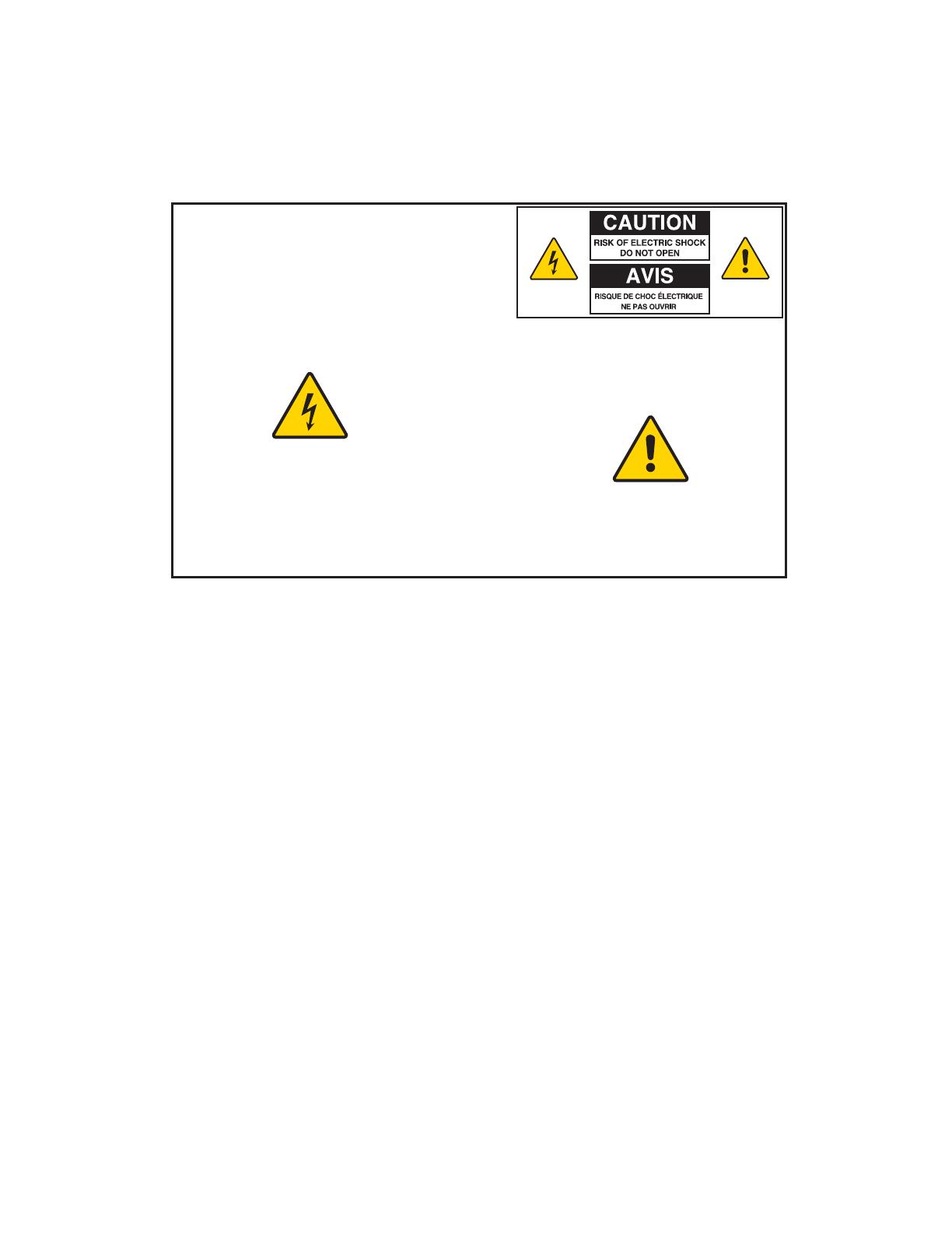
CAUTION: To reduce the risk of electric shock, do not
remove cover (or back). No user-serviceable parts
inside. Refer servicing to qualified service personnel.
WARNING
TO PREVENT FIRE OR ELECTRIC SHOCK, DO NOT
EXPOSE THIS UNIT TO RAIN OR MOISTURE.
For this apparatus, the coaxial cable shield/screen shall be
grounded as close as practical to the point of entry of the cable
into the building. For products sold in the US and Canada, this
reminder is provided to call the system installer's attention to
Article 820-93 and Article 820-100 of the NEC (or Canadian
Electrical Code Part 1), which provides guidelines for proper
grounding of the coaxial cable shield.
This symbol is intended to alert you that uninsulated voltage
within this product may have sufficient magnitude to cause
electric shock.Therefore, it is dangerous to make any kind of
contact with any inside part of this product.
Ce symbole a pour but d’alerter toute personne qu’un contact
avec une pièce interne de ce produit, sous tension et non isolée,
pourrait être suffisant pour provoquer un choc électrique. Il est
donc dangereux d’être en contact avec toute pièce interne de
ce produit.
This symbol is intended to alert you of the presence
of important operating and maintenance (servicing)
instructions in the literature accompanying this product.
Ce symbole a pour but de vous avertir qu’une
documentation importante sur le fonctionnement et
l’entretien accompagne ce produit.
iii
Contents
IMPORTANT SAFETY INSTRUCTIONS ......................................................................................iv
What’s in the Carton? ...................................................................................................................vi
Additional Equipment You Might Need .........................................................................................vi
Welcome .......................................................................................................................................1
Safety First ...................................................................................................................................1
Identify Your Set-Top .................................................................................................................... 1
Front Panel Features .................................................................................................................... 2
Back Panel Connectors ................................................................................................................3
Connecting the Set-Top ................................................................................................................ 4
Connections for an HDTV and VCR ............................................................................................. 5
Connections for a Standard-De nition TV and VCR .................................................................... 6
View Television Programming ...................................................................................................... 7
Troubleshooting ............................................................................................................................ 8
Frequently Asked Questions......................................................................................................... 9
Picture Formats .......................................................................................................................... 10
Connecting to an HDTV with an HDMI Connector ......................................................................11
Connecting to an HDTV with a DVI Connector........................................................................... 12
Connecting to an HDTV with Component Input (YPbPr) ............................................................ 13
Connecting to a Home Theater System with Component Input (YPbPr) .................................... 14
Connecting to a Stereo VCR and HDTV (optional) .................................................................... 15
Connecting the Set-Top in HD Mode to an SDTV with Component Input (YPbPr) .................... 16
Connecting an External SATA Hard Disk Drive (optional) .......................................................... 17
Index ...........................................................................................................................................19
Compliance Information..............................................................................................................21
iv
IMPORTANT SAFETY INSTRUCTIONS
Ground the Product
WARNING: Avoid electric shock and re hazard!
If this product connects to coaxial cable wiring, be sure
the cable system is grounded (earthed). Grounding
provides some protection against voltage surges and
built-up static charges.
Outdoor Grounding System
If this product connects to an outdoor antenna or cable system,
be sure the antenna or cable system is grounded (earthed).
This provides some protection against voltage surges and
built-up static charges.
Article 810 of the National Electric Code (NEC) ANSI/NFPA
No. 70-1990, provides the following information:
Grounding of the mast and supporting structure
Grounding the lead-in wire to an antenna discharge unit
Size of the grounding conductors
Location of the antenna-discharge unit
Connection to grounding electrodes
Requirements for the grounding electrodes (see the
following antenna grounding diagram as recommended
by NEC ANSI/NFPA 70)
1) Read these instructions.
2) Keep these instructions.
3) Heed all warnings.
4) Follow all instructions.
5) Do not use this apparatus near water.
6) Clean only with dry cloth.
7) Do not block any ventilation openings. Install in
accordance with the manufacturers instructions.
8) Do not install near any heat sources such as radiators,
heat registers, stoves, or other apparatus (including
ampli ers) that produce heat.
9) Do not defeat the safety purpose of the polarized or
grounding-type plug. A polarized plug has two blades with
one wider than the other. A grounding-type plug has two
blades and a third grounding prong. The wide blade or the
third prong are provided for your safety. If the provided
plug does not t into your outlet, consult an electrician
for replacement of the obsolete outlet.
10) Protect the power cord from being walked on or pinched
particularly at plugs, convenience receptacles, and the
point where they exit from the apparatus.
11) Only use attachments/accessories specified by the
manufacturer.
12)
Use only with the cart, stand, tripod, bracket, or
table speci ed by the manufacturer, or sold with
the apparatus. When a cart is used, use caution
when moving the cart/apparatus combination to avoid
injury from tip-over.
13) Unplug this apparatus during lightning storms or when
unused for long periods of time.
14) Refer all servicing to qualified service personnel.
Servicing is required when the apparatus has been
damaged in any way, such as a power-supply cord or plug
is damaged, liquid has been spilled or objects have fallen
into the apparatus, the apparatus has been exposed to
rain or moisture, does not operate normally, or has been
dropped.
Power Source Warning
A label on this product indicates the correct power source
for this product. Operate this product only from an electrical
outlet with the voltage and frequency indicated on the product
label. If you are uncertain of the type of power supply to your
home or business, consult your service provider or your local
power company.
The AC inlet on the unit must remain accessible and operable
at all times.
WARNING: Avoid electric shock and re hazard!
Do not locate an outside antenna system in the vicinity of
overhead power lines or power circuits. Touching power
lines or circuits might be fatal.
v
IMPORTANT SAFETY INSTRUCTIONS, continued
Protect the Product from Lightning
In addition to disconnecting the AC power from the wall outlet,
disconnect the signal inputs.
Verify the Power Source from the On/Off
Power Light
When the on/off power light is not illuminated, the apparatus
may still be connected to the power source. The light may go
out when the apparatus is turned off, regardless of whether
it is still plugged into an AC power source.
Eliminate AC Mains Overloads
WARNING: Avoid electric shock and re hazard!
Do not overload AC mains, outlets, extension cords,
or integral convenience receptacles. For products
that require battery power or other power sources to
operate them, refer to the operating instructions for
those products.
Provide Ventilation and Select a Location
Remove all packaging material before applying power to
the product.
Do not place this apparatus on a bed, sofa, rug, or similar
surface.
Do not place this apparatus on an unstable surface.
Do not install this apparatus in an enclosure, such as a
bookcase or rack, unless the installation provides proper
ventilation.
Do not place entertainment devices (such as VCRs or
DVDs), lamps, books, vases with liquids, or other objects
on top of this product.
Do not block ventilation openings.
Protect from Exposure to Moisture and Foreign
Objects
WARNING: Avoid electric shock and re hazard! Do
not expose this product to dripping or splashing liquids,
rain, or moisture. Objects lled with liquids, such as
vases, should not be placed on this apparatus.
WARNING: Avoid electric shock and re hazard!
Unplug this product before cleaning. Clean only with a dry
cloth. Do not use a liquid cleaner or an aerosol cleaner. Do
not use a magnetic/static cleaning device (dust remover)
to clean this product.
WARNING: Avoid electric shock and re hazard!
Never push objects through the openings in this product.
Foreign objects can cause electrical shorts that can result
in electric shock or re.
Service Warnings
WARNING: Avoid electric shock! Do not open the
cover of this product. Opening or removing the cover
may expose you to dangerous voltages. If you open the
cover, your warranty will be void. This product contains
no user-serviceable parts.
Check Product Safety
Upon completion of any service or repairs to this product, the
service technician must perform safety checks to determine
that this product is in proper operating condition.
Protect the Product When Moving It
Always disconnect the power source when moving
the apparatus or connecting or disconnecting cables.
20080717_UL60065 for Cable_US/Canada
vi
What’s In The Carton?
The set-top carton contains the following items:
8450HDC and 8550HDC DVR
with M-Card
Quick Reference Guide
• Power Cord
POWER
SELECT
VOL+VOL-
CH+
CH-
LISTEXITINFOGUIDE
L AUDIO IN R VIDEO IN
Explorer 8550HDC
Additional Equipment You Might Need
You might need some of the cables and adapters shown below for connecting the set-top to your home entertainment
devices. See the connection information in the Connection Diagrams section for more information.
Check with your service provider for information about acquiring cables or adapters, or you can purchase cables or
adapters at your local electronics supplier.
Optical Digital
Audio Cable
RF Coaxial
Cable
Coaxial Digital
Audio Cable
HDMI
Adapter
RGB
Adapter
S-Video
Cable
HDMI-to-HDMI
Cable
HDMI-to-DVI
Cable
Composite
A/V Cables
RGB Adapter
Cable
(RCA to RCA)
RGB Adapter
Cable
(RCA to VGA)
RGB Adapter
Cable
(RCA to BNC)
Component
Video Cables
(YPbPr)
Audio Left/
Right Cable
POWER
SELECT
VOL+VOL-
CH+
CH-
LISTEXITINFOGUIDE
L AUDIO IN R VIDEO IN
Explorer 8550HDC
1
Welcome
The Cisco
®
Explorer
®
8450HDC and 8550HDC DVR Set-Tops with Multi-Stream CableCARD
(M-Card
) provide
high-de nition (HD) capability and broadband digital video services.
Follow the instructions in this guide to install the 8450HDC and 8550HDC, to become familiar with the buttons on the
front panel, and to access your cable services. Then, enjoy the features of the 8450HDC and 8550HDC and change
the way you watch TV.
Important: If the M-Card is removed, the set-top will not operate correctly.
The consumer support website provides news and information about this product. For more information, please refer to
www.scienti catlanta.com/products/consumers/new_cableboxes.htm
Safety First
Before using the set-top, read the Important Safety Instructions section of this guide.
Identify Your Set-Top
To nd the serial number for your set-top, look on the back for a label that is similar to the example shown here.
The serial number begins with “SA“ and is located at the top of the bar code.
If your set-top requires troubleshooting in the future, your cable service provider may ask for this serial number.
Use the space provided here to record the serial number: _______________________________________________
eCM MAC: 001868C16907
STB RF MAC: 001868C16906
STB SN: SABNFSRVG
T13039
Serial Number
2
Front Panel Features
1 Power Turns the DVR on and off
2 USB Connects to external USB devices (Reserved for future use)
3 VOL +, VOL - Increases and decreases the volume
4 CH+, CH - Scrolls through the channels
5 Select Accesses your on-screen selection
6 IR Sensor Receives the infrared signal from the remote control
7 Guide Accesses the on-screen guide (if de ned), Quick Settings, or General Settings guide
8 Info Displays a description of the selected program. This button is available from the on-screen
guide and while viewing a program
9 Exit Exits menus, the on-screen guide, and program information
10 List Displays the Recorded List
11 LED Display Displays the selected channel number and time of day.
The LED also displays the following:
Message (
)
HDTV
Power (
)
Output Resolution (1080i, 720p, 480p, or 480i)
AUTO - Automatically outputs native scan rates that your TV can accept
12 Video and Not available on all models. Connects to video and left/right (L/R) audio outputs from a TV
Audio Input or other device. (Not available on 8540HDC)
Note: This illustration may vary from the actual product.
POWER
SELECT
VOL+VOL-
CH+
CH-
LISTEXITINFOGUIDE
L AUDIO IN R VIDEO IN
Explorer 8550HDC
T13662
1 278910653
11 12
4
CAUTION: The DVR is equipped with a hard disk drive to store programs that you record and to allow you to rewind
and pause live TV. Any time the DVR is powered on (power LED is illuminated) or a recording is in progress (the
record LED is illuminated) the hard disk is in use.
If you need to move the DVR, complete the following steps to allow the hard disk to shut down properly. First, make
sure that no recording is in progress (record LED is off). Then, turn off power by pressing the Power key. Finally,
unplug the unit and wait 10 seconds for the hard disk drive to spin down (stop). At this point the unit can be moved
safely.
You should handle this product with the same level of care you would use when handling other electronics containing
a hard disk drive, such as a laptop computers or other hard disk drive equipped devices.
3
Back Panel Connectors
1 Cable In Connects to a coaxial cable that delivers the signal from your service provider
2 Set-Top Bar Code Contains set-top serial number and MAC addresses
3 Archive Video Connects to a video input of an archive device
4 L-R Audio Archive Connects to an audio input of an archive device
5 Video 1 (Composite) Connects to a video input of another device, such as a TV or VCR
6 Audio Out (Left/Right) Connects to RCA cables that send analog audio signals (left/right) to a stereo receiver
or TV with stereo inputs
7 YPbPr Connects to the component video input (YPbPr) on an HDTV. Do not use
these cables if you are using the HDMI connection
8 Out 2 Connects to either a VCR or to another set of inputs (composite) on your TV
(Secondary Audio Out)
9 Digital Audio Out Connects to an RCA cable that sends a digital audio signal to a surround-sound receiver
or other digital audio device
10 S-Video Out Connects to S-Video input of a standard TV or VCR
11 IR Connector reserved for future use
12 Optical Audio Out Connects to an optical cable that sends a digital audio signal to a surround-sound
receiver or other digital audio device
13 Cable Out Connects to a coaxial cable that sends analog audio and video signals to a TV or VCR.
These signals are SDTV video and stereo audio
14 HDMI Connects an HDMI
cable to the HDMI input of an HDTV. HDMI supports both digital audio
and video. May be used to connect to a DVI interface using an HDMI-to-DVI adapter for
video and separate audio connections. Any of the following audio connections may be used:
Digital Audio Out (9); Audio Out: Left, Right (6); or Optical Audio Out (12)
15 M-CARD Installed by your service provider
16 USB 2.0 Connects to external USB devices (Reserved for future use)
17 eSATA Connects an external Serial ATA (eSATA) hard disk drive for expanded drive space.
A connected eSATA drive is not an archival device. Your service provider may not
support all eSATA hard drives
18 M-CARD Code Label Contains M-CARD serial number and MAC address
19 1394 Connects to display devices equipped with a 1394 input
20 Ethernet Connects to an Ethernet-equipped device (Reserved for future use)
21 AC Outlet Connects to the AC power cord from another device, such as a TV
22 AC Power Input Connects to the power cord to deliver power to the set-top
Note: This illustration may vary from the actual product.
THIS DEVICE IS INTENDED TO BE ATTACHED TO A
RECEIVER THAT IS NOT USED TO RECEIVE OVER-THE-AIR
BROADCAST SIGNALS. CONNECTION OF THIS DEVICE
IN ANY OTHER FASHION MAY CAUSE HARMFUL
INTERFERENCE TO RADIO COMMUNICATIONS
AND IS IN VIOLATION OF THE FCC RULES, PART 15.
CABLE OUT
S-VIDEO
OUT
USB 2.0
120VAC
60Hz 80W
120 VAC
60Hz 4.2A
500W
OPTICAL
AUDIO
OUT
MULTI-STREAM CABLE CARD
VIDEO
ARCHIVE OUT 1
L
R
VIDEO
L
R
Pb
Y
Pr
DIGITAL
AUDIO
L
R
IR
1394
AVI S:
RISQUE DE CHOC
ELECTRIQUE NE PAS OUVRIR
CAUTION
RISK OF ELECTRIC SHOCK
DO NOT OPEN
1394
eSATA
CABLE
IN
SCIENTIFIC-ATLANTA, INC.
CATV CONVERTER
MADE IN MEXICO
LISTED 14H1
VIDEO PRODUCT
eCM MAC: 001AC3F4F757
STB RF MAC: 001AC3F$F756
STB SN: SABPQBQGD
M-CARD SN: PKCPKPDBT
M-CARD MAC: 001AC326910A
T13663
19
119
7 864 16
13
1 2 14
15 1810
17 20 22
12
3 215
4
Connecting the Set-Top
To connect your set-top to your entertainment devices, complete these steps.
Identify the additional devices you
will connect to the set-top and TV.
See the Connection Diagrams
section of this guide.
Determine if your TV is HD or SD
and whether it is wide-screen (16:9)
or standard-screen (4:3). See page
10 for more information.
4
3
16
9
or
Make the connections for your TV and VCR as follows:
If you are using an HDTV, see page 5 and the connection diagrams at the end of this guide.
If you are using an SDTV, see page 6 and the connection diagrams at the end of this guide.
If you want to archive some programs to VCR tape, see pages 5 and 6 and the connection
diagrams at the end of this guide.
1
2
4
Plug the set-top and the TV into an AC power source that is not controlled by a switch.
Do not turn on the set-top or TV yet.
5
POWER
It may take several minutes for the set-top to receive the latest software, programming, and service
information. Wait until you see one of the following displays on the front panel of the set-top that
indicates that the update is complete:
Current time Four dashes (- - - -)
Note: If four dashes appear, you must call your service provider to get the set-top authorized.
Set up your set-top for HDTV or SDTV by completing the following steps:
Make sure the set-top is Off and the TV is On.
On the front panel of the set-top, press GUIDE and INFO at the same time.
Follow the on-screen instructions to choose HD or SD mode and wide-screen (16:9) or standard
screen (4:3) depending upon your TV type. See Page 10 for more information on the scan rate.
At the conclusion of the on-screen instructions, press POWER on the set-top to begin watching TV.
6
7
VCR
DVD
Other
Home Theater
External SATA Drive
3
5
Connections for an HDTV and VCR
To use the set-top with an HDTV, you must make one of the following connections to view the HD content. In addition,
you can make connections to a digital or analog VCR to record to a VCR tape. Refer to your TV and VCR user guides
and the cabling diagrams in this guide for more detailed connection information.
Note: The labeling on your set-top, HDTV, and VCR may vary slightly.
DVI
HDMI
YPbPr
RGB
For VCRs with Video and Left and Right audio connectors, you
can use the Out 2 connectors (Video, Left, and Right) on the
set-top.
See the connection diagram on page 15 for an example.
VCR
For VCRs with S-Video and Left and Right audio
connectors, you can use the S-Video Out and the
Out 2 Left and Right connectors on the set-top.
Required Connections to an HDTV (use one)
Optional Connections to a VCR (use one)
Set-Top
Connections
HDTV
Connections
Set-Top
Connections
VCR
Connections
Pr
Pb
Y
L R
DVI
VIDEO
OUT 2
L
A
U
D
I
O
R
VIDEO
IN
L R
AUDIO
IN
L
R
OUT 1
Y
Pr
Pb
L
R
OUT 1
L R
Y
Pr
Pb
L
R
OUT 1
B
R
G
V
H
L R
S-VIDEO
OUT
L
R
OUT 2
S-VIDEO
IN
L R
Adapter Needed
Some HDTVs have a High-De nition Multimedia Interface (HDMI)
connector. The HDMI connector provides both a digital video and
audio connection.
See the connection diagram on page 11 for an example.
The YPbPr connectors can provide high-de nition component
video signals to an HDTV.
Note: Use the HD Setup Wizard on the set-top to set the HD
mode and select the output video format that will matches the
full capabilities of your HDTV.
See the connection diagram on page 13 for an example.
The HDMI connector can provide the connection to an HDTV
with a DVI input. If your HDTV has a Digital Visual Interface (DVI)
connector, you will need an HDMI-to-DVI adapter, and you will
need to connect a separate audio connection.
See the connection diagram on page 12 for an example.
Some HDTVs have only RGB connectors. If you have one of
these HDTVs, you need an RGB adapter.
Check with your service provider for information about acquiring
an RGB adapter, or you can purchase the adapter at your local
electronics supplier.
Adapter Needed
6
Connections for a Standard-Definition TV and VCR
When using the set-top with an SDTV, you must make one of the following connections to view content. Some SDTVs
may not have all these connections. In addition, you can make connections to a VCR to record to a VCR tape. Refer
to your TV and VCR user guides and the cabling diagrams in this guide for more detailed information.
Note: The labeling on your set-top, SDTV, and VCR may vary slightly.
YPbPr
For VCRs with Video and Left and Right audio connectors, you
can use the Out 2 connectors (Video, Left, and Right) on the
set-top.
VCR
Required Connections to an SDTV (use one)
Optional Connection to a VCR
The YPbPr connectors can provide standard-de nition component
video signals to an SDTV.
Note: To connect YPbPr to an SDTV, you must set the HD Setup
Wizard on the set-top to HD Mode, and select the output video
format (typically 480i) that will match the capabilities of your SDTV.
The S-Video Out connection provides an optimal video connection
to SDTVs.
The Cable Out connector provides a video and audio connection
to an SDTV.
CABLE
OUT
CABLE IN/
ANT IN
Y
Pr
Pb
Pr
Pb
Y
L
R
OUT 1
L R
Set-Top
Connections
SDTV
Connections
Set-Top
Connections
VCR
Connections
VIDEO
OUT 2
L
A
U
D
I
O
R
VIDEO
IN
L R
AUDIO
IN
S-VIDEO
OUT
L
R
OUT 2
S-VIDEO
IN
L R
S-VideoCable Out
7
View Television Programming
Access Services and Programs
Access cable services and programs by pressing the following keys on the remote control:
Guide–Access the on-screen guide. The on-screen guide displays schedules of TV programs and other services
available from your cable service provider, such as video-on-demand and pay-per-view programs.
Arrows–Select a program in the schedule.
Info–Display a speci c program description (either from the on-screen guide or while viewing a program).
Select–View a speci c program in the guide.
Stretch and Zoom Program
You can stretch and zoom SD or HD programs by pressing the # key on the remote control.
Avoid Screen Burn-In
Images such as letterbox bars or side bars, bright closed-captioning backgrounds, station logos, or any other
stationary images may cause the picture tube in your HDTV to age unevenly; this is known as screen burn-in.
Refer to the user guide that came with your HDTV for more information.
WARNING: Avoid screen burn-in. Do not display the same xed images on your HDTV screen for
extended periods of time.
8
Troubleshooting
If the set-top does not perform as expected, the following tips may help. If you need further assistance, contact your
service provider.
No Picture
Verify that the M-Card module is installed.
Verify that the power to your TV is turned on.
Verify that your HDTV is in HD mode. If necessary, run the HD Setup Wizard to select HD mode.
If the set-top is plugged into a wall switch, verify that the switch is in the ON position.
Note: You should avoid plugging the set-top into an outlet controlled by a wall switch.
Verify that all cables are properly connected.
If your system includes a VCR or stereo, verify that you have properly connected them to the set-top.
Verify that the set-top is set to the proper screen type and resolution.
No Color
Verify that the current TV program is broadcast in color.
Adjust the TV color controls.
If you are using a component video connection (YPbPr), check that all connectors are completely plugged into
the set-top and TV.
No Sound
If your setup includes a VCR or stereo, verify that you have properly connected them to the set-top.
Verify that the volume is turned up.
Verify that the mute function is not on.
Automatic Software Updates
A message appears on the TV screen when the set-top and the M-Card module are receiving software updates.
In addition, download information also appears on the front panel of the set-top during these updates. Wait for the
current time to display on the front panel before continuing. When the time appears, the update is complete.
9
Frequently Asked Questions
What is Digital Television?
Digital television (DTV) is a huge leap forward in television technology compared to analog television that has been
widely available since the 1940s. DTV is delivered and displayed using digital encoding, similar to the way a PC
operates. By using digital technology, there is no variation in picture and sound quality from the origination point until
it is displayed on your television. You always receive a high-quality picture without the wavy lines or static you might
sometimes get from a weak analog signal.
Because DTV receives and displays digital images that contain many times more picture elements (pixels - the small
dots that make up the color image on your screen) than standard analog television, you can get a sharper on-screen
image than with analog. Additionally, DTV supports CD-quality sound. DTV includes SDTV (Standard De nition
Television), EDTV (Enhanced De nition Television), and HDTV (High-De nition Television). That means that all
HDTV is digital, but not all digital TV is high-de nition. A high-de nition program must originate in HD format and be
broadcast in HD format. Having an HDTV system does not mean that everything you watch will be in high-de nition.
Getting the signal from digital cable also does not mean it is high-de nition.
What is Standard-Definition Television?
Standard-de nition television (SDTV) is basic digital television programming delivered by cable. Typically, the SDTV
screen is the same, nearly square shape as an analog television screen. Digital images on an SDTV set are crisp
and clear—noticeably better than on a standard analog television set using an antenna to receive over-the-air
signals.
What is High-Definition Television?
High-de nition television (HDTV) is a completely new way to send and receive television broadcast signals. HDTV
images are made up of pixels that are much smaller and closer together than those used in standard analog
television, and there are millions of them. Thus, HDTV can display ve to six times the detail of analog television
to deliver picture quality that is much more realistic, dimensional, and precise. SDTV programs can be viewed on
an HDTV. Another feature of HDTV is digital surround sound using Dolby
®
Digital technology, which is the same
technology used to produce the sound you hear in movie theaters.
Are Local TV Stations Broadcasting in HDTV?
Many local TV stations are transmitting digital signals. However, transmitting a digital signal does not mean
transmitting an HDTV signal. Some stations are using the new bandwidth to broadcast several standard-de nition
channels. Most stations, once they begin broadcasting in digital, are offering HD content from their parent network
(for example, CBS, ABC, NBC, Fox, WB, UPN, and PBS).
Where Are the Connection Diagrams?
The diagrams at the end of this guide show examples of common ways to connect the set-top to your HDTV, DVD,
and home theater receiver. However, these diagrams do not show every possible combination of devices. Refer to
the user guides that came with your other electronic devices for further information.
What Cables Do I Need?
Some of the cables and adaptors shown in the diagrams may not be included with the set-top. Some of the required
cables are shown in the connection diagrams and on page vi of this guide.
10
Picture Formats
What is the Difference Between a Standard-Screen and a Wide-Screen HDTV?
The type of screen your HDTV has (wide-screen or standard-screen) determines how the set-top displays programs
on the screen. The picture format for an HDTV is a combination of aspect ratio and screen resolution and is different
for standard-screen and wide-screen HDTVs.
What is Aspect Ratio?
An aspect ratio is the ratio of the width to the height of the TV screen. The aspect ratios differ because the television
industry manufactures both standard-screen and wide-screen HDTVs to appeal to consumer viewing preferences.
What is the Screen Resolution and Scan Rate?
The screen resolution indicates the amount of detail that the picture displays. Resolution is identi ed by the number
of display lines on the screen. The techniques that an HDTV uses to “paint” the picture on the screen are referred to
as progressive and interlaced.
With the progressive method, the lines are drawn on the screen one at a time in sequential order. The interlaced
method involves refreshing pixels in alternation — rst the odd lines and then the even lines.
For advance setup, select the scan modes that your TV can support. Refer to your set-top and HDTV user guides to
choose the proper scan rates (480i, 480p, 720p, 1080i) for your setup.
For example, a resolution of 1080i indicates that the screen shows 1080 lines in an interlaced display, and 480p
indicates that the screens shows 480 lines in a progressive display.
Notes:
The screen resolution (1080i, 480p, and so forth) is sometimes referred to as the scan rate.
The terms are interchangeable.
You can stretch and zoom the displayed picture using the built-in capability of the set-top by pressing the # key on
the remote control.
A standard-screen HDTV has a 4x3 aspect
ratio. The screen is 4 units wide for every
3 units tall.
A wide-screen HDTV is one-third wider than a
standard-screen HDTV. The screen is 16 units
wide for every 9 units tall.
A screen resolution of 480p or 480i lls
the screen.
A screen resolution of 720p or 1080i lls the screen.
4
3
16
9
11
Connecting to an HDTV with an HDMI Connector
Required cables:
1 HDMI-to-HDMI cable
Important Notes Regarding the HDMI Interface on the Set-Top
The HDMI interface automatically con gures the audio output for a format supported by the television. Because not all
TVs support the Dolby
®
Digital input, the HDMI interface may automatically select a 2-channel stereo audio con guration
instead of Dolby Digital, which it carries over to the other digital audio outputs of the set-top. This prevents your home
theater system or Dolby Digital decoder from providing the full Dolby Digital surround-sound effect.
You can override this con guration by completing the following steps.
1. Press SETTINGS twice on the remote control to open the General Settings menu.
2. Press MOVE UP or MOVE DOWN to select the option Audio: Digital Out.
3. Press MOVE RIGHT to select Dolby Digital. This setting will send Dolby Digital audio to the HDMI, DIGITAL
AUDIO OUT, and OPTICAL AUDIO OUT connectors on the set-top.
Notes:
If the TV is not Dolby Digital capable, it may not produce audio through its speakers when the Audio: Digital Out
setting on the set-top is set to Dolby Digital. You can either switch the Audio: Digital Out setting back to HDMI
when you are not using the home theater or Dolby Digital decoder, or you can connect the baseband audio outputs
(OUT 1 Audio Left and Right) to the TV.
Digital content is encrypted with High-Bandwidth Content Protection (HDCP) on the DVI/HDMI port. This set-top
is not compatible with devices that do not support HDCP. You must use either the YPbPr or 1394 connection to
connect the set-top to these devices.
CABLE OUT
S-VIDEO
OUT
USB 2.0
120VAC
60Hz 80W
120 VAC
60Hz 4.2A
500W
OPTICAL
AUDIO
OUT
MULTI-STREAM CABLE CARD
VIDEO
ARCHIVE OUT 1
L
R
VIDEO
L
R
Pb
Y
Pr
DIGITAL
AUDIO
L
R
IR
1394 1394
eSATA
CABLE
IN
M-CARD SN: PKCPKPDBT
M-CARD MAC: 001AC326910A
THIS DEVICE IS INTENDED TO BE ATTACHED TO A
RECEIVER THAT IS NOT USED TO RECEIVE OVER-THE-AIR
BROADCAST SIGNALS. CONNECTION OF THIS DEVICE
IN ANY OTHER FASHION MAY CAUSE HARMFUL
INTERFERENCE TO RADIO COMMUNICATIONS
AND IS IN VIOLATION OF THE FCC RULES, PART 15.
AVI S:
RISQUE DE CHOC
ELECTRIQUE NE PAS OUVRIR
CAUTION
RISK OF ELECTRIC SHOCK
DO NOT OPEN
SCIENTIFIC-ATLANTA, INC.
CATV CONVERTER
MADE IN MEXICO
LISTED 14H1
VIDEO PRODUCT
eCM MAC: 001AC3F4F757
STB RF MAC: 001AC3F$F756
STB SN: SABPQBQGD
C
ABLE OUT
S
-VIDE
O
OU
T
U
SB 2.
0
120VAC
C
60
Hz
80W
1
20 VA
C
0Hz 4.2
500
W
OPTICAL
A
UDI
O
OUT
MULTI-
S
TREAM CABLE CAR
D
V
IDE
O
A
R
C
HIVE
O
UT
1
L
R
V
IDE
O
L
R
Pb
Y
Pr
r
r
D
I
G
ITAL
A
UDI
O
L
R
IR
1394 1394
eS
AT
A
C
ABL
E
IN
M
-CARD SN: PKCPKPDB
T
M
-CARD MAC: 001AC326910A
CABLE
IN
Back of HDTV
HDMI
AUDIO
CENTER
CHANNEL IN
AUDIO IN
DVI/HDCP
ANT (75 )
INOUT
LR
ANT-1
HD 2
Y
OUT
ANT-2
PB
PR
L
R
VIDEO
L/
MONO
R
L/
MONO
R
AUDIO
IN
ON OFF
IN
HD 1
S-VIDEO
VIDEO
Y
PB
PR
L
R
AUDIOAUDIO
Explorer Set-top
Cable
Input
T13666
WARNING: Electric shock hazard! Unplug all electronic devices before connecting or disconnecting
any device cables to the set-top.
12
Connecting to an HDTV with a DVI Connector
Required cables:
1 HDMI-to-DVI or 1 HDMI-to-HDMI cable and 1 DVI adapter
1 audio Left/Right cable
Notes:
When you connect the HDMI connector to the DVI connector on your HDTV, you need an HDMI-to-DVI adaptor and
a separate audio connection.
Digital content is encrypted with High-Bandwidth Content Protection (HDCP) on the DVI/HDMI port. This set-top is
not compatible with devices that do not support HDCP. You must use either the YPbPr or 1394 connection (which
uses Digital Transmission Content Protection, or DTCP) to connect the set-top to these devices.
Also refer to the Important Notes Regarding the HDMI Interface on the Set-Top on page 11.
CABLE OUT
S-VIDEO
OUT
USB 2.0
120VAC
60Hz 80W
120 VAC
60Hz 4.2A
500W
OPTICAL
AUDIO
OUT
MULTI-STREAM CABLE CARD
VIDEO
ARCHIVE OUT 1
L
R
VIDEO
L
R
Pb
Y
Pr
DIGITAL
AUDIO
L
R
IR
1394 1394
eSATA
CABLE
IN
M-CARD SN: PKCPKPDBT
M-CARD MAC: 001AC326910A
THIS DEVICE IS INTENDED TO BE ATTACHED TO A
RECEIVER THAT IS NOT USED TO RECEIVE OVER-THE-AIR
BROADCAST SIGNALS. CONNECTION OF THIS DEVICE
IN ANY OTHER FASHION MAY CAUSE HARMFUL
INTERFERENCE TO RADIO COMMUNICATIONS
AND IS IN VIOLATION OF THE FCC RULES, PART 15.
AVI S:
RISQUE DE CHOC
ELECTRIQUE NE PAS OUVRIR
CAUTION
RISK OF ELECTRIC SHOCK
DO NOT OPEN
SCIENTIFIC-ATLANTA, INC.
CATV CONVERTER
MADE IN MEXICO
LISTED 14H1
VIDEO PRODUCT
eCM MAC: 001AC3F4F757
STB RF MAC: 001AC3F$F756
STB SN: SABPQBQGD
CABLE OU
T
S
-VIDEO
OU
T
US
B 2.0
120VAC
C
6
0Hz 80
W
1
20 VA
C
Hz 4.2
500
W
O
PTI
C
AL
A
UDI
O
OUT
MULTI-STREAM CABLE CAR
D
V
IDEO
ARCHIV
E
OUT
1
L
R
VIDE
O
L
R
P
b
Y
Pr
r
r
D
IGITAL
AU
DI
O
L
R
IR
13
9
4
1
3
94
eSAT
A
CABLE
IN
M-
C
ARD
S
N: PK
C
PKPDB
T
M-
C
ARD MA
C
:
00
1A
C3
2
69
1
0A
CABLE
IN
OUT 1
L
R
Back of HDTV
AUDIO
CENTER
CHANNEL IN
ANT (75 )
INOUT
ANT-1
HD 2
Y
OUT
ANT-2
PB
PR
L
R
VIDEO
L/
MONO
R
L/
MONO
R
AUDIO
IN
ON OFF
IN
HD 1
S-VIDEO
VIDEO
Y
PB
PR
L
R
AUDIOAUDIO
DVI/HDCP
IN
AUDIO IN
DVI/HDCP
LR
Explorer Set-top
Cable
Input
T13665
WARNING: Electric shock hazard! Unplug all electronic devices before connecting or disconnecting
any device cables to the set-top.
13
Connecting to an HDTV with Component Input (YPbPr)
Required cables:
1 set component video cables (YPbPr)
1 audio Left/Right cable
CABLE OUT
S-VIDEO
OUT
USB 2.0
120VAC
60Hz 80W
120 VAC
60Hz 4.2A
500W
OPTICAL
AUDIO
OUT
MULTI-STREAM CABLE CARD
VIDEO
ARCHIVE OUT 1
L
R
VIDEO
L
R
Pb
Y
Pr
DIGITAL
AUDIO
L
R
IR
1394 1394
eSATA
CABLE
IN
M-CARD SN: PKCPKPDBT
M-CARD MAC: 001AC326910A
THIS DEVICE IS INTENDED TO BE ATTACHED TO A
RECEIVER THAT IS NOT USED TO RECEIVE OVER-THE-AIR
BROADCAST SIGNALS. CONNECTION OF THIS DEVICE
IN ANY OTHER FASHION MAY CAUSE HARMFUL
INTERFERENCE TO RADIO COMMUNICATIONS
AND IS IN VIOLATION OF THE FCC RULES, PART 15.
AVI S:
RISQUE DE CHOC
ELECTRIQUE NE PAS OUVRIR
CAUTION
RISK OF ELECTRIC SHOCK
DO NOT OPEN
SCIENTIFIC-ATLANTA, INC.
CATV CONVERTER
MADE IN MEXICO
LISTED 14H1
VIDEO PRODUCT
eCM MAC: 001AC3F4F757
STB RF MAC: 001AC3F$F756
STB SN: SABPQBQGD
CABLE OU
T
S
-VIDE
O
O
UT
U
SB 2.0
120VAC
C
6
0Hz 80
W
1
20 VA
C
60Hz 4.2
500
W
O
PTI
C
A
L
AUDIO
OUT
MU
LTI-
S
TREAM
C
ABLE
C
AR
D
V
IDE
O
AR
C
HIV
E
OUT
1
L
R
VIDE
O
L
R
Pb
Y
Pr
r
r
D
IGITAL
AUDIO
L
R
IR
1
39
4
1
39
4
e
S
AT
A
C
ABLE
IN
M-CARD SN: PKCPKPDB
T
M-
C
ARD MA
C
: 001A
C3
26910
A
OUT 1
Pb
Y
Pr
L
R
CABLE
IN
Back of
HDTV
DVI/HDCP
IN
AUDIO
CENTER
CHANNEL IN
AUDIO IN
DVI/HDCP
ANT (75 )
INOUT
LR
ANT-1
HD 2
Y
OUT
ANT-2
PB
PR
L
R
VIDEO
L/
MONO
R
L/
MONO
R
AUDIO
IN
ON OFF
IN
HD 1
S-VIDEO
VIDEO
Y
PB
PR
L
R
AUDIOAUDIO
Explorer Set-top
Cable
Input
T13664
WARNING: Electric shock hazard! Unplug all electronic devices before connecting or disconnecting
any device cables to the set-top.
14
Note: This connection assumes
that audio is provided by the home
theater speakers.
Back of
HDTV
DVI/HDCP
IN
AUDIO
CENTER
CHANNEL IN
AUDIO IN
DVI/HDCP
ANT (75½)
INOUT
LR
ANT-1
HD 2
Y
OUT
ANT-2
PB
PR
L
R
AUDIO
VIDEO
L/
MONO
R
L/
MONO
R
VIDEO-1 VIDEO-2
AUDIO
IN
ON OFF
IN
HD 1
S-VIDEO
VIDEO
Y
PB
PR
L
R
AUDIOAUDIO
Back of Home Theater Receiver
VIDEO
COMPONENT VIDEO
1
Y
PB
PR
2
Y
PB
PR
Y
PB
PR
L
R
AUDIO
S-VIDEO
DIGITAL
AUDIO
TV/CABLE
1
2
3
4
VIDEO
L
R
AUDIO
S-VIDEO
DVD
VIDEO
L
R
AUDIO
S-VIDEO
VIDEO 1
S-VIDEO
OUT
VIDEO OUT
MONITOR
L
R
AUDIO
S-VIDEO
OUTIN
OUTIN
T11136
VIDEO
Back of
DVD Player
AUDIO OUT
LR
VIDEO
OUT
DIGITAL
OUT
COAXIAL
S-VIDEO
OUT
OPTICAL
DIGITAL OUT
COMPONENT VIDEO OUT/
PROGRESSIVE SCAN
PB PBY
Back of Home Theater Receiver
VIDEO
COMPONENT VIDEO
1
Y
PB
PR
2
Y
PB
PR
Y
PB
PR
L
R
AUDIO
S-VIDEO
DIGITAL
AUDIO
TV/CABLE
1
2
3
4
VIDEO
L
R
AUDIO
S-VIDEO
DVD
VIDEO
L
R
AUDIO
S-VIDEO
VIDEO 1
S-VIDEO
OUT
VIDEO OUT
MONITOR
VIDEO
L
R
AUDIO
S-VIDEO
OUTIN
OUTIN
T11135
Connecting to a Home Theater System
with Component Input (YPbPr)
Required cables:
3 sets component video cables (YPbPr)
1 audio Left/Right cable
2 coaxial digital audio cables
CABLE OUT
S-VIDEO
OUT
USB 2.0
120VAC
60Hz 80W
120 VAC
60Hz 4.2A
500W
OPTICAL
AUDIO
OUT
MULTI-STREAM CABLE CARD
VIDEO
ARCHIVE OUT 1
L
R
VIDEO
L
R
Pb
Y
Pr
DIGITAL
AUDIO
L
R
IR
1394 1394
eSATA
CABLE
IN
M-CARD SN: PKCPKPDBT
M-CARD MAC: 001AC326910A
THIS DEVICE IS INTENDED TO BE ATTACHED TO A
RECEIVER THAT IS NOT USED TO RECEIVE OVER-THE-AIR
BROADCAST SIGNALS. CONNECTION OF THIS DEVICE
IN ANY OTHER FASHION MAY CAUSE HARMFUL
INTERFERENCE TO RADIO COMMUNICATIONS
AND IS IN VIOLATION OF THE FCC RULES, PART 15.
AVI S:
RISQUE DE CHOC
ELECTRIQUE NE PAS OUVRIR
CAUTION
RISK OF ELECTRIC SHOCK
DO NOT OPEN
SCIENTIFIC-ATLANTA, INC.
CATV CONVERTER
MADE IN MEXICO
LISTED 14H1
VIDEO PRODUCT
eCM MAC: 001AC3F4F757
STB RF MAC: 001AC3F$F756
STB SN: SABPQBQGD
CABLE OU
T
S-VIDE
O
OUT
US
B 2.0
120VAC
C
60
Hz
80W
12
0
VA
C
60Hz 4.2A
5
00
W
O
PTI
C
A
L
AUDIO
OUT
M
ULTI-STREAM CABLE CAR
D
VIDE
O
A
RCHIV
E
O
UT
1
L
R
V
IDEO
L
R
P
b
Y
Pr
r
r
D
IGITA
L
AUDIO
L
R
IR
1
39
4
139
4
e
SATA
C
ABL
E
IN
M
-
C
ARD
S
N: PK
C
PKPDBT
M
-
C
ARD MA
C
:
00
1A
C3
2
69
1
0
A
OUT 1
Pb
Y
Pr
DIGITAL
AUDIO
CABLE
IN
Back of Home
Theater Receiver
COMPONENT VIDEO
1
Y
PB
PR
2
Y
PB
PR
Y
PB
PR
S-VIDEO
DIGITAL
AUDIO
TV/CABLE
1
2
3
4
VIDEO
L
R
AUDIO
S-VIDEO
DVD
VIDEO
L
R
AUDIO
VIDEO
L
R
AUDIO
S-VIDEO
VIDEO 1
S-VIDEO
OUT
VIDEO OUT
MONITOR
VIDEO
L
R
AUDIO
S-VIDEO
OUTIN
OUTIN
Explorer Set-top
Cable
Input
T1366
7
WARNING: Electric shock hazard! Unplug all electronic devices before connecting or disconnecting
any device cables to the set-top.
  • Page 1 1
  • Page 2 2
  • Page 3 3
  • Page 4 4
  • Page 5 5
  • Page 6 6
  • Page 7 7
  • Page 8 8
  • Page 9 9
  • Page 10 10
  • Page 11 11
  • Page 12 12
  • Page 13 13
  • Page 14 14
  • Page 15 15
  • Page 16 16
  • Page 17 17
  • Page 18 18
  • Page 19 19
  • Page 20 20
  • Page 21 21
  • Page 22 22
  • Page 23 23
  • Page 24 24
  • Page 25 25
  • Page 26 26
  • Page 27 27
  • Page 28 28

Cisco 8450HDC User manual

Category
Digital Video Recorders (DVR)
Type
User manual
This manual is also suitable for

Ask a question and I''ll find the answer in the document

Finding information in a document is now easier with AI