Campbell RAWS-F Owner's manual
- Category
- Weather stations
- Type
- Owner's manual

RAWS-F Remote
Automated Weather Station
for Fire Weather
Revision: 12/13
Copyright © 2006-2013
Campbell Scientific, Inc.


Warranty
“PRODUCTS MANUFACTURED BY CAMPBELL SCIENTIFIC, INC. are
warranted by Campbell Scientific, Inc. (“Campbell”) to be free from defects in
materials and workmanship under normal use and service for twelve (12)
months from date of shipment unless otherwise specified in the corresponding
Campbell pricelist or product manual. Products not manufactured, but that are
re-sold by Campbell, are warranted only to the limits extended by the original
manufacturer. Batteries, fine-wire thermocouples, desiccant, and other
consumables have no warranty. Campbell’s obligation under this warranty is
limited to repairing or replacing (at Campbell’s option) defective products,
which shall be the sole and exclusive remedy under this warranty. The
customer shall assume all costs of removing, reinstalling, and shipping
defective products to Campbell. Campbell will return such products by surface
carrier prepaid within the continental United States of America. To all other
locations, Campbell will return such products best way CIP (Port of Entry)
INCOTERM® 2010, prepaid. This warranty shall not apply to any products
which have been subjected to modification, misuse, neglect, improper service,
accidents of nature, or shipping damage. This warranty is in lieu of all other
warranties, expressed or implied. The warranty for installation services
performed by Campbell such as programming to customer specifications,
electrical connections to products manufactured by Campbell, and product
specific training, is part of Campbell’s product warranty. CAMPBELL
EXPRESSLY DISCLAIMS AND EXCLUDES ANY IMPLIED
WARRANTIES OF MERCHANTABILITY OR FITNESS FOR A
PARTICULAR PURPOSE. Campbell is not liable for any special, indirect,
incidental, and/or consequential damages.”

Assistance
Products may not be returned without prior authorization. The following
contact information is for US and international customers residing in countries
served by Campbell Scientific, Inc. directly. Affiliate companies handle
repairs for customers within their territories. Please visit
www.campbellsci.com to determine which Campbell Scientific company serves
your country.
To obtain a Returned Materials Authorization (RMA), contact CAMPBELL
SCIENTIFIC, INC., phone (435) 227-9000. After an application engineer
determines the nature of the problem, an RMA number will be issued. Please
write this number clearly on the outside of the shipping container. Campbell
Scientific’s shipping address is:
CAMPBELL SCIENTIFIC, INC.
RMA#_____
815 West 1800 North
Logan, Utah 84321-1784
For all returns, the customer must fill out a “Statement of Product Cleanliness
and Decontamination” form and comply with the requirements specified in it.
The form is available from our web site at www.campbellsci.com/repair. A
completed form must be either emailed to repair@campbellsci.com or faxed to
(435) 227-9106. Campbell Scientific is unable to process any returns until we
receive this form. If the form is not received within three days of product
receipt or is incomplete, the product will be returned to the customer at the
customer’s expense. Campbell Scientific reserves the right to refuse service on
products that were exposed to contaminants that may cause health or safety
concerns for our employees.

Table of Contents
PDF viewers: These page numbers refer to the printed version of this document. Use the
PDF reader bookmarks tab for links to specific sections.
1. Introduction.................................................................1
2. Getting Started............................................................3
3. Station Siting and Orientation ...................................6
3.1 General Description .............................................................................6
3.2 Air Temperature and Relative Humidity..............................................6
3.3 Precipitation .........................................................................................7
3.4 Solar Radiation.....................................................................................7
3.5 Wind Speed and Direction ...................................................................7
3.6 Barometric Pressure (optional).............................................................7
3.7 Fuel Moisture and Fuel Temperature (optional) ..................................7
4. Sensor Maintenance, Calibration, and
Troubleshooting .......................................................7
4.1 Maintenance .........................................................................................7
4.2 Air Temperature and Relative Humidity..............................................8
4.2.1 General Description ......................................................................8
4.2.2 Wiring ...........................................................................................9
4.2.3 Maintenance..................................................................................9
4.2.4 Calibration.....................................................................................9
4.2.5 Troubleshooting ............................................................................9
4.3 Rain Gage.............................................................................................9
4.3.1 General Description ......................................................................9
4.3.2 Wiring .........................................................................................10
4.3.3 Maintenance................................................................................10
4.3.4 Calibration...................................................................................10
4.3.5 Troubleshooting ..........................................................................11
4.4 Solar Radiation...................................................................................11
4.4.1 General Description ....................................................................11
4.4.2 Wiring .........................................................................................12
4.4.3 Maintenance................................................................................12
4.4.4 Calibration...................................................................................12
4.4.5 Troubleshooting ..........................................................................12
4.5 Wind Speed and Direction .................................................................13
4.5.1 Wind Sensor................................................................................13
4.5.1.1 General Description..........................................................13
4.5.1.2 Wiring ..............................................................................14
4.5.1.3 Maintenance .....................................................................14
4.5.1.4 Calibration........................................................................14
4.5.1.5 Troubleshooting ...............................................................14
i

Table of Contents
4.5.2 2-D WindSonic (optional).......................................................... 14
4.5.2.1 General Description......................................................... 14
4.5.2.2 Wiring.............................................................................. 15
4.5.2.3 Maintenance .................................................................... 15
4.5.2.4 Calibration ....................................................................... 15
4.5.2.5 Troubleshooting............................................................... 16
4.6 Barometric Pressure (optional).......................................................... 16
4.6.1 General Description.................................................................... 16
4.6.2 Wiring ........................................................................................ 16
4.6.3 Maintenance ............................................................................... 17
4.6.4 Calibration.................................................................................. 17
4.6.5 Troubleshooting ......................................................................... 17
4.7 Fuel Moisture and Fuel Temperature (optional)................................ 17
4.7.1 General Description.................................................................... 17
4.7.2 Wiring ........................................................................................ 18
4.7.3 Maintenance ............................................................................... 18
4.7.4 Calibration.................................................................................. 19
4.7.5 Troubleshooting ......................................................................... 19
5. Equipment Maintenance, Calibration, and
Troubleshooting .....................................................19
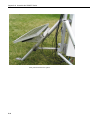
5.1 Solar Panels ....................................................................................... 19
5.1.1 General Description.................................................................... 19
5.1.2 Wiring ........................................................................................ 19
5.1.3 Maintenance ............................................................................... 20
5.1.4 Calibration.................................................................................. 20
5.1.5 Troubleshooting ......................................................................... 20
5.2 Charger/Regulator ............................................................................. 20
5.2.1 General Description.................................................................... 20
5.2.2 Wiring ........................................................................................ 21
5.2.3 Maintenance ............................................................................... 21
5.2.4 Calibration.................................................................................. 21
5.2.5 Troubleshooting ......................................................................... 21
5.3 Battery ............................................................................................... 22
5.3.1 General Description.................................................................... 22
5.3.2 Wiring ........................................................................................ 22
5.3.3 Maintenance ............................................................................... 22
5.3.4 Calibration.................................................................................. 22
5.3.5 Troubleshooting ......................................................................... 23
5.4 GOES Transmitter (Optional) ........................................................... 23
5.4.1 General Description.................................................................... 23
5.4.2 Wiring ........................................................................................ 24
5.4.3 Maintenance ............................................................................... 24
5.4.4 Calibration.................................................................................. 25
5.4.5 Troubleshooting ......................................................................... 25
5.5 CR1000 Keyboard/Display ............................................................... 25
5.5.1 General Description.................................................................... 25
5.5.2 Wiring ........................................................................................ 25
5.5.3 Maintenance ............................................................................... 26
5.5.4 Calibration.................................................................................. 26
5.5.5 Troubleshooting ......................................................................... 26
5.6 CR1000 Datalogger ........................................................................... 26
5.6.1 General Description.................................................................... 26
5.6.2 Wiring ........................................................................................ 27
ii

Table of Contents
5.6.3 Maintenance................................................................................27
5.6.4 Calibration...................................................................................27
5.6.5 Troubleshooting ..........................................................................27
6. Desiccant...................................................................27
7. References ................................................................28
8. RAWS Orientation.....................................................28
8.1 Determining True North and Sensor Orientation ...............................28
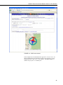
8.2 USGS Web Calculator .......................................................................30
Appendices
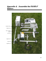
A.
Assemble the RAWS-F Station .............................. A-1
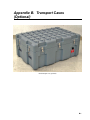
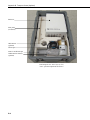
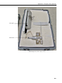
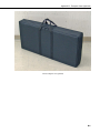
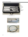
B. Transport Cases (Optional).................................... B-1
Figures
1-1. Color-coded, keyed connector panel....................................................1
1-2. RAWS-F Quick Deployment Weather Station. Some wiring
not shown..........................................................................................2
2-1. Inside environmental enclosure (optional equipment shown)..............4
4-1. Air temperature and relative humidity .................................................8
4-2. Rain gage and CS300-QD pyranometer.............................................10
4-3. Pyranometer .......................................................................................11
4-4. Wind sensor........................................................................................13
4-5. 2-D WindSonic ..................................................................................15
4-6. Barometric pressure ...........................................................................16
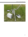
4-7. CS516-QD Fuel Moisture/Fuel Temperature .....................................18
5-1. 12-volt charger/regulator....................................................................20
5-2. GOES transmitter ...............................................................................24
5-4. CR1000 Keyboard/Display ................................................................25
5-5. CR1000 and printed circuit wiring panel ...........................................26
5-6. Printed circuit board wiring panel connector ID ................................27
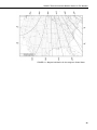
8-1. Magnetic declination for the contiguous United States......................29
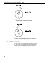
8-2. A declination angle east of True North (positive) is subtracted
from 360 (0) degrees to find True North ........................................30
8-3. A declination angle west of True North (negative) is subtracted
from 0 (360) degrees to find True North ........................................30
8-4. USGS web calculator .........................................................................31
Tables
2-1. Public Variables ...................................................................................5
4-1. TEMP/RH Connector (color coded orange).........................................9
4-2. PRECIP Connector (color coded blue) ..............................................10
4-3. SOLAR RAD SDI-12 Connector (color coded green).......................12
4-4. WS/WD Connector (color coded red)................................................14
iii

Table of Contents
iv
4-5. SDI-12 Connector (color coded yellow)............................................ 15
4-6. CS100-QD Wiring............................................................................. 16
4-7. FM/FT Connector (color coded brown) ............................................ 18
5-1. GOES Transmitter Connections ........................................................ 24

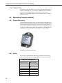
RAWS-F Remote Automated Weather
Station for Fire Weather
1. Introduction
The RAWS-F Fire Weather Quick Deployment Station is a lightweight, pre-
configured station that can be set up in less than 10 minutes—without tools
(see Section 2, Getting Started). The aluminum environmental enclosure
houses a 12 V rechargeable battery and a CR1000 datalogger mounted to a 6 ft
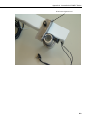
tripod. The outside of the enclosure has color-coded, keyed connectors
(FIGURE 1-1) for attaching the sensors. Besides the connectors, a wiring
panel is included allowing the measurement of additional sensors. The
RAWS-F typically communicates via our GOES satellite transmitter. It is also
compatible with other communication equipment such as telephones, digital
cellular transceivers, and radios. This station is ideal for prescribed burns or
other temporary installations. The RAWS-F Quick Deployment Weather
Station is shown in FIGURE 1-2.
Specifications are available from our web site at www.campbellsci.com.
For “sensors specifications,” click on “Products”, select “Sensors” and go to
the sensor manual for specifications. For “equipment specifications”, enter the
part number in the “Search” box on the website mentioned above and go to the
equipment manual for specifications.
Equipment and sensor specifications are provided on the
ResourceDVD which ships with the RAWS-F.
NOTE
FIGURE 1-1. Color-coded, keyed connector panel
1

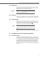
RAWS-F Remote Automated Weather Station for Fire Weather
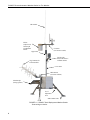
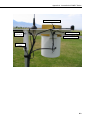
RF antenna
TE525
(adjust level)
CS300-QD
is behind the
TE525
Yagi antenna for
TX320 satellite
Crossarm
(face north to south)
HC2S3-QD
housed in 41003-5
radiation shield
Upper mas
t
Lower mast
GPS antenna
(used with TX320)
SP10/20-QD
(facing equator)
Level
adjustment
lever
Stake anchor holes
FIGURE 1-2. RAWS-F Quick Deployment Weather Station.
Some wiring not shown.
2

RAWS-F Remote Automated Weather Station for Fire Weather
2. Getting Started
Set up and test your station before field deployment (Appendix A).
Level the RAWS to ensure the sensors are level. Level the rain gage by
adjusting the rain gage leveling screw. A post level and compass ship with the
station (pn 16670).
Keep this manual and the CR1000KD Keyboard Display with
the RAWS.
NOTE
Review the station siting and orientation section before field deployment. If a
problem is encountered, review the equipment wiring and troubleshooting
sections in this manual.
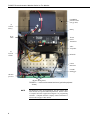
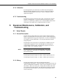
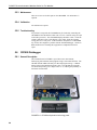
After siting and leveling the RAWS, open the enclosure and (1) connect the
battery cable and (2) verify the CH100 switch is in the ‘on’ position.
When this equipment is not in use (for example, transport or
storage), disconnect battery cable to the CH100.
NOTE
3

RAWS-F Remote Automated Weather Station for Fire Weather
VSP3
Vosponder
RF Radio
(1)
Connect
battery
(2)
Turn on
CH100
CR1000KD
packed in foam
(may go here)
SC12
Cable
Battery
TX320
GOES
Transmitter
CS100
Barometer
CR1000
Datalogger
CR1000
power in
CR1000 Wiring Panel
FIGURE 2-1. Inside environmental enclosure (optional equipment
shown)
The RAWS-F comes pre-programmed, but this program does
NOT include user-specific GOES-ID parameters. Please contact
a Campbell Scientific Applications Engineer for programming
assistance. Campbell Scientific company contact information is
listed on the last page of this manual.
NOTE
4

RAWS-F Remote Automated Weather Station for Fire Weather
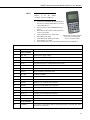
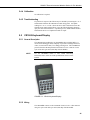
Use the CR1000KD Keyboard
Display to see the “Public
Variables” shown in TABLE 2-1.
NOTE
• Connect the CR1000KD Keyboard Display to
the CS I/O connector (FIGURE 5-5) or SC12
Cable (FIGURE 2-1)
• Press any key for the CR1000KD Power up
Screen
• Press Enter to move down a menu (Press Esc
to move up a menu)
• (Press up/down arrow to select item)
Press any key for Power up Screen
Press ^ to turn on/off backlight
Press <> to adjust contrast
• Select Data, press Enter
• Select Real Time Tables, press Enter
• Select Public, press Enter
• Press up/down arrow to see the Public Variables listed in TABLE 2-1
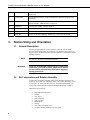
TABLE 2-1. Public Variables
Number Name Function
Sensor Variables
1 Batt_Volt System power supply voltage
2 AirTempF HC2S3 air temperature in degrees F
3 RH HC2S3 relative humidity in percent
4 TdewF Dewpoint in degrees F, calculated from HC2S3 data
5 SlrW Solar radiation in watts, pyranometer
6 Rain_in Temporary rain, cleared every scan
7 RainTot TE525 cumulative rain fall in inches
8 WS_mph Wind speed in MPH
9 WindDir Wind direction
10 WSDiag Only for WindSonic data, zero otherwise
11 MaxWS MaxWS, reset 2 minutes before transmit
12 MaxWD Direction of wind during max wind speed
13 SlrMJ Solar radiation in MJoules
14 BP_inHg Hourly — barometric pressure, inHg
15 BPelev_ft Elevation, to correct barometric pressure
16 FuelT_F Hourly — fuel temperature in degrees F
17 FuelM Hourly — fuel moisture, % moisture by weight
GOES Variables
18 CountDwn True or False: True indicates GPS fix good and program is collecting data. False
until GPS fix is obtained
5

RAWS-F Remote Automated Weather Station for Fire Weather
19 Clockgood True or False: True after GPS fix and CR1000 clock has been set to match
TX320 clock
20 TimeToXmit Seconds until transmit time. Indicates CR1000 and TX320 are properly setup
and running
21 SWR Standing Wave Ratio (SWR), only after a transmission. Indicates condition of
antenna and cable. SWR should be less than 2.0
22 FwdPower Forward power in dBm, should be about 37
23 RefPower Reflected power in dBm, should be about 25 or less
24 RC_Data Only valid after first transmission. Anything other than zero is a problem
25 Setup_RC Indicates if CR1000 could setup TX320. Zero is success or has not run
3. Station Siting and Orientation
3.1 General Description
Selecting an appropriate site for the RAWS is critical in order to obtain
accurate meteorological data. In general, the site should be representative of
the general area of interest and away from the influence of obstructions such as
buildings and trees.
See Section 7, References, for siting references.
NOTE
If any part of the weather station comes in contact with
power lines, you could be killed. Contact local utilities
for the location of buried utility lines before digging or
driving ground rods.
WARNING
3.2 Air Temperature and Relative Humidity
A temperature and relative humidity (RH) sensor should be located over an
open level area at least 9 m in diameter (EPA). The surface should be covered
by short grass, or where grass does not grow, the natural earth surface. The
sensor must be housed inside a radiation shield and adequately ventilated.
Situations to avoid include:
• large industrial heat sources
• rooftops
• steep slopes
• sheltered hollow
• high vegetation
• shaded areas
• swamps
• areas where snow drifts occur
• low places holding standing water after rains
6

RAWS-F Remote Automated Weather Station for Fire Weather
3.3 Precipitation
A rain gage should be located over an open level area covered by short grass,
or where grass does not grow, the natural earth surface. Level the RAWS
station to ensure the sensors are level. Level the rain gage by adjusting the rain
gage leveling screw. A post level and compass ship with the RAWS (pn
16770).
Take off the funnel and remove the rubber band securing the
tipping bucket mechanism during transport.
NOTE
3.4 Solar Radiation
A solar radiation sensor should be located to avoid shadows on the sensor at
any time. Orient the RAWS facing the equator, minimizing the chance of
shading from other weather station structures. Reflective surfaces and sources
of artificial radiation should be avoided. Level the RAWS to ensure the solar
radiation sensor is level.
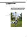
3.5 Wind Speed and Direction
A wind sensor should be located over open level terrain and at a distance of at
least ten times (EPA) the height of any nearby building, tree, or other
obstruction.
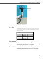
3.6 Barometric Pressure (optional)
The barometric pressure sensor is mounted to the back plate inside the RAWS
environmental enclosure.
3.7 Fuel Moisture and Fuel Temperature (optional)
The fuel moisture and fuel temperature sensor should be left outside at the field
site continually exposed to the same conditions as the forest fuels. The fuel
moisture and fuel temperature dowel rods absorb and desorb moisture from its
surroundings. Install the probes horizontally on the mounting stake and face
the sensors towards the equator above a representative forest floor duff layer.
Place the sensor away from foot traffic areas.
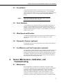
4. Sensor Maintenance, Calibration, and
Troubleshooting
4.1 Maintenance
Proper maintenance of weather station components is essential to obtain
accurate data. Equipment must be in good operating condition, which requires
a program of regular inspection and maintenance. Routine and simple
maintenance can be accomplished by the person in charge of the weather
station. More difficult maintenance, such as sensor calibration, sensor
performance testing (for example, bearing torque), and sensor component
replacement, generally requires sending the instrument to Campbell Scientific.
7

RAWS-F Remote Automated Weather Station for Fire Weather
A station log should be maintained for each weather station that includes
equipment model, serial numbers, and maintenance that was performed.
Contact Campbell Scientific, phone (435) 227-9000, for an RMA
number before returning sensor or equipment for service.
NOTE
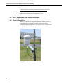
4.2 Air Temperature and Relative Humidity
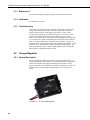
4.2.1 General Description
Rotronic’s HydroClip2 Air Temperature and Relative Humidity Sensor (pn
HC2S3-QD) shown in FIGURE 4-1 contains a Platinum Resistance
Thermometer (PRT) and a Rotronic’s IN1 capacitive sensor. The probe has a
voltage output for each sensor.
FIGURE 4-1. Air temperature and relative humidity
8

RAWS-F Remote Automated Weather Station for Fire Weather
4.2.2 Wiring
The HC2S3 attaches to the connector labeled TEMP/RH, which is color coded
orange. This sensor is internally wired from the RAWS connector panel to the
CR1000.
TABLE 4-1. TEMP/RH Connector (color coded orange)
Connector Pin Description CR1000 Terminal
A Temperature H 1L
B Sensor Excitation VX1
C Sensor Signal L/
D Power Ground G
E RH Signal 1H
F Switched 12 V SW_12V
4.2.3 Maintenance
The temp/RH sensor requires minimal maintenance. Check monthly to make
sure the radiation shield is free from debris. The filter at the end of the sensor
should also be checked for contaminates. When installed in close proximity to
the ocean or other bodies of salt water, a coating of salt may build up on the
radiation shield, sensor, filter and even the RH chip. A buildup of salt on the
filter or RH chip will delay or destroy the response to atmospheric humidity.
The filter can be rinsed gently in distilled water. If necessary, the chip can be
removed and rinsed as well. Do not scratch the RH chip while cleaning.
4.2.4 Calibration
Recalibrate the temp/RH sensor annually. Obtain an RMA number before
returning this sensor to Campbell Scientific for recalibration.
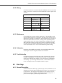
4.2.5 Troubleshooting
If a problem is suspected, check the sensor cable. Disconnect the connector
and look for damaged pins. Verify that the sensor body is connected to the
sensor head. Under the filter assembly, verify the sensors are connected but
not touching. Try connecting a substitute sensor. Obtain an RMA number
before returning this sensor to Campbell Scientific for repair.
4.3 Rain Gage
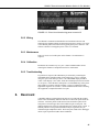
4.3.1 General Description
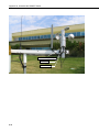
The Texas Electronics Rain Gage (pn TE525-QD) shown in FIGURE 4-2 is an
adaptation of a Weather Bureau tipping bucket rain gage. The rain gage has a
6 inch collector. The rain gage sensor output has a switch closure for each
bucket tip. Level the rain gage by adjusting the rain gage leveling screw. A
post level and compass (pn 16670) ship with the station.
9

RAWS-F Remote Automated Weather Station for Fire Weather
FIGURE 4-2. Rain gage and CS300-QD pyranometer
4.3.2 Wiring
The TE525-LQ attaches to the connector labeled PRECIP, which is color
coded blue. This sensor is internally wired from the RAWS connector panel to
the CR1000.
TABLE 4-2. PRECIP Connector (color coded blue)
Connector Pin Description CR1000 Terminal
A Tipping Bucket C6
B 5 V 5V
C Ground G
4.3.3 Maintenance
The rain gage funnel and bucket mechanism must be kept clean. Routinely
check for and remove any foreign material, dust, insects, etc.
4.3.4 Calibration
Recalibrate the rain gage annually. Obtain an RMA number before returning
this sensor to Campbell Scientific for recalibration.
10

RAWS-F Remote Automated Weather Station for Fire Weather
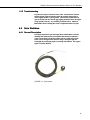
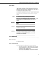
4.3.5 Troubleshooting .3.5 Troubleshooting
If a problem is suspected, check the sensor cable. Disconnect the connector
and use a digital volt meter (DVM) to check the resistance between Pin A
(sensor signal) and Pin C (sensor ground). The resistance should read as an
open circuit until you move the rain gage tipping mechanism where the magnet
swings past the reed relay. Try connecting a substitute sensor. Obtain an
RMA number before returning this sensor to Campbell Scientific for repair.
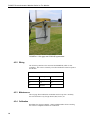
4.4 Solar Radiation 4.4 Solar Radiation
4.4.1 General Description 4.4.1 General Description
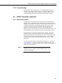
The Apogee Pyranometer (pn CS300-QD) shown in FIGURE 4-3 measures
incoming solar radiation with a silicon photovoltaic detector mounted in a
cosine-corrected head. The detector outputs current; a shunt resistor in the
sensor converts the signal from current to voltage. During the night, the
CS300-QD may read slightly negative incoming solar radiation. The negative
signal is caused by RF noise.
FIGURE 4-3. Pyranometer
11

RAWS-F Remote Automated Weather Station for Fire Weather
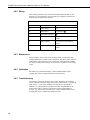
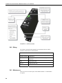
4.4.2 Wiring
The CS300-LQ attaches to the connector labeled SOLAR RAD SDI-12; this
connector is color coded green. The pyranometer is internally wired from the
RAWS connector panel to the CR1000.
TABLE 4-3. SOLAR RAD SDI-12 Connector (color coded green)
Connector Pin Description CR1000 Terminal
A Solar Sensor + 3H
B Solar Sensor - 3L shorted to
C Solar Sensor Ground
D SDI-12 Ground G (used for a second SDI-12
sensor)
E SDI-12 Signal C5 (used for a second SDI-12
sensor)
F SDI-12 12 V 12V (used for a second SDI-12
sensor)
4.4.3 Maintenance
The pyranometer must be kept clean. Routinely check for and remove any
foreign material, dust or debris on the sensor head. The debris can be removed
with a blast of compressed air or with a soft bristle, camel hair brush. Handle
the sensor carefully when cleaning. Be careful not to scratch the surface of the
sensor.
4.4.4 Calibration
Recalibrate the pyranometer annually. Obtain an RMA number before
returning this sensor to Campbell Scientific for recalibration.
4.4.5 Troubleshooting
If a problem is suspected, check the sensor cable. Disconnect the connector
and use a DVM to check the voltage between Pin A Solar Sensor (+) and Pin B
Solar Sensor (-). The voltage should be 0 to 200 mV for 0 to 1000 W m
-2
radiation. No voltage indicates a problem with either the photodiode or the
shunt resistor, both of which are potted in the sensor head and cannot be
serviced. Try connecting a substitute sensor. Obtain an RMA number before
returning this sensor to Campbell Scientific for repair.
12
Page is loading ...
Page is loading ...
Page is loading ...
Page is loading ...
Page is loading ...
Page is loading ...
Page is loading ...
Page is loading ...
Page is loading ...
Page is loading ...
Page is loading ...
Page is loading ...
Page is loading ...
Page is loading ...
Page is loading ...
Page is loading ...
Page is loading ...
Page is loading ...
Page is loading ...
Page is loading ...
Page is loading ...
Page is loading ...
Page is loading ...
Page is loading ...
Page is loading ...
Page is loading ...
Page is loading ...
Page is loading ...
Page is loading ...
Page is loading ...
Page is loading ...
Page is loading ...
Page is loading ...
Page is loading ...
Page is loading ...
Page is loading ...
Page is loading ...
Page is loading ...
-
 1
1
-
 2
2
-
 3
3
-
 4
4
-
 5
5
-
 6
6
-
 7
7
-
 8
8
-
 9
9
-
 10
10
-
 11
11
-
 12
12
-
 13
13
-
 14
14
-
 15
15
-
 16
16
-
 17
17
-
 18
18
-
 19
19
-
 20
20
-
 21
21
-
 22
22
-
 23
23
-
 24
24
-
 25
25
-
 26
26
-
 27
27
-
 28
28
-
 29
29
-
 30
30
-
 31
31
-
 32
32
-
 33
33
-
 34
34
-
 35
35
-
 36
36
-
 37
37
-
 38
38
-
 39
39
-
 40
40
-
 41
41
-
 42
42
-
 43
43
-
 44
44
-
 45
45
-
 46
46
-
 47
47
-
 48
48
-
 49
49
-
 50
50
-
 51
51
-
 52
52
-
 53
53
-
 54
54
-
 55
55
-
 56
56
-
 57
57
-
 58
58


Campbell RAWS-F Owner's manual
- Category
- Weather stations
- Type
- Owner's manual
Ask a question and I''ll find the answer in the document
Finding information in a document is now easier with AI
Related papers
-
Campbell Scientific RAWS-H Owner's manual
-
-
-
-
-
-
-
-
-
Other documents
-
 Columbia Lighting COL-CSL8-8040 CSL Striplight User manual
-
Align HEC10001 Owner's manual
-
DFI CS100 FCC Certification
-
-
-
-
AcuRite Wind Cup Assembly for 5-in-1 Weather Sensor User manual
-
-
-
 Wel-Bilt 45 Watt Solar Kit Owner's manual

