Niles HDLCR User manual

Category
Loudspeakers
Type
User manual
I N S T A L L A T I O N G U I D E
HDLCR
FOR USE IN MULTI-CHANNEL MUSIC OR HOME THEATER SYSTEMS
HIGH DEFINITION, LEFT/CENTER/RIGHT CHANNEL, IN-WALL LOUDSPEAKER
Thank you for choosing the HDLCR High-Definition, Left/Center/Right Channel In-Wall
Loudspeaker from Niles. With proper installation and operation, you should enjoy years of
trouble-free use.
Niles manufactures the industry’s most complete line of custom installation components and
accessories for audio/video systems. To see the complete Niles product assortment, visit us on
the Internet at: www.nilesaudio.com
TABLE OF CONTENTS
Introduction 1
Features and Benefits 1
Installation Considerations 3
Speaker Placement 6
Installation Fundamentals 9
New Construction: Installing A Bracket 14
Existing Construction: Installing A Bracket 16
Finishing the Installation 17
Operation 22
Removing the Grille and Speaker 22
Specifications 23
Limited Warranty 24
Warranty Registration Card 25
CONGRATULATIONS!
NILES AUDIO CORPORATION 1-800-BUY-HIFI
INTRODUCTION
The Niles HDLCR High-Definition, Left/Center/Right Channel, In-Wall Loudspeaker is expressly
designed for superior sonic quality in front-, center-, or rear-channel applications. It employs
advanced technology components that extract the subtle nuances in recorded music or the thun
-
derous action sound in a movie. The HDLCR is the perfect choice wherever quality of sound is the
most important consideration.
FEATURES AND BENEFITS
INJECTION-MOLDED TCC WOOFERS WITH BUTYL-
RUBBER SURROUND, LONG-THROW VOICE COIL/
MAGNET STRUCTURE, AND VENTED POLE PIECE
The HDLCR features newly-developed woofer-cone material that combines injection-molded
polypropylene with talc, carbon, and ceramic (TCC) stiffening agents. As a result, the cone offers
extreme stiffness and light weight for accurate, dynamic response. A long-throw voice coil/magnet
structure ensures increased cone excursion to enhance low frequency response and dynamic
impact. Additionally, each woofer employs a vented pole piece for increased bass linearity and a
butyl-rubber surround for improved midrange damping and clarity as well as moisture resistance.
1-INCH TETERON TRI-LAMINATE TWEETER HOUSED IN A
PRECISION ADJUSTMENT MECHANISM
The HDLCR’s Teteron Tweeter employs a tri-laminate design consisting of an inner textile layer,
which forms the dome, a high damping layer to kill unwanted resonances, and an outside layer of
urethane to add stiffness and prevent breakup modes. The result is a transparently clear, sweet,
natural-sounding tweeter, which still maintains extended frequency response. This advanced
tweeter is housed in a precision adjustment mechanism, which permits the tweeter to be ac
-
curately positioned after installation for optimum performance and without the diffraction distortion
typical of traditional pivoting tweeters.
DIRECTED SOUND FIELD GEOMETRY™ (DSFG) DELIVERS
OPTIMUM PHASE RESPONSE TO LISTENERS AND COM
-
PENSATES FOR HIGH SPEAKER PLACEMENT
The HDLCR employs Niles’ Directed Sound Field Geometry (DSFG). With DSFG, the tweeter is offset
from the center of the dual woofers. The resulting acoustic interaction between the woofers and
the offset tweeter results in the flattest frequency and phase response, approximately 15-degrees
off-axis from the tweeter. This gives optimum performance to a seated listener, even if the loud
-
speaker is mounted above a built-in TV.
1
2
INSTALLER-SELECTABLE ACOUSTIC FINE TUNING
Using the baffle-mounted TREBLE and BASS CUT controls, the installer can de-emphasize the bass and/
or treble response by 3 dB after installing the HDLCR to precisely tone match the sound in any room.
CTR L/R MODE SWITCH
The HDLCR includes a baffle-mounted CTR L/R mode switch to optimize performance in applications
as either a center channel or left/right loudspeaker for front-channel use.
EASY RETROFIT INSTALLATION IN YOUR EXISTING HOME
Designed for ease of installation, the Niles mounting system makes retrofit installations simple and
fast. A supplied template assures fast and accurate hole cutting. The bracket slips behind the drywall
and the screws secure the bracket to the frame, sandwiching the drywall between them. The speaker
baffle attaches to the frame, and the grille mounts over the speaker.
THREE-STAGE INSTALLATION SYSTEM FOR REMODELS OR
NEW CONSTRUCTION
Only the parts needed are installed during a particular stage of construction. After framing and wiring
are finished, the bracket is installed. After the drywall is up, but before the painter begins to paint, the
frame is installed, and the rustproof aluminum grille is left for the painter to match to the surround
-
ings. The speaker is installed only when construction is completely finished. Masking or prepping the
speaker for painting and worries about speaker theft during final construction are never an issue!
MICROPERF™ ALUMINUM GRILLES
Niles’ exclusive MicroPerf™ grille construction provides an exceptionally tight hole pattern for
acoustic transparency at all audio frequencies and enables the speaker elements to remain invisible.
MicroPerf aluminum grilles can also be painted to blend seamlessly with the surrounding decor.
Additionally, the aluminum grille material will never rust or discolor over time.
INFRARED SENSOR MOUNT
The speaker baffle has a locator designed for the Niles MS-100 MicroSensor
®
, a miniature infrared
sensor. The MS-100 installs discreetly behind the aluminum grille to minimize wall clutter in the home.
To control the equipment, the listener simply points the remote control at the speaker from up to
15 feet away.
NILES AUDIO CORPORATION 1-800-BUY-HIFI
3
Figure 1. Mounting an HDLCR
loudspeaker into an wall.
NILES’ HD HIGH-DEFINITION VOICE MATCHING
Ensures compatibility with other Niles HD High-Definition in-wall, on-wall, and ceiling-mount
models to accommodate a wide range of system designs.
DOLBY
®
DIGITAL READY
The HDLCR is specifically designed for Home Theater Sound. This model exceeds the specifications
set forth by Dolby Laboratories for the accurate reproduction of Dolby Digital-Encoded Sources.
INSTALLATION CONSIDERATIONS
Bracket
New Construction Wings
Frame
Speaker Baffle
Acoustic Fine
Tuning Controls
IR Sensor Knockout
Grille
TOOLS AND PRECAUTIONS
We recommend using the following tools to install a HDLCR loudspeaker:
Electric drill with 1/4- and 1/2-inch drill bits, and a 1-inch flat drill bit
(for drilling through studs)
Keyhole or drywall saw
Stiff wire, fish tape, or glow rods (for routing cables)
Phillips screwdriver set
Cable ties
Pencil
Level
Rubber gloves and protective eyewear
Before starting the installation, please observe the following precautions:
Turn off all system power before making any connections.
Always wear protective eyewear when using tools.
Make sure hands are clean before installation.
Wear gloves when working with fiberglass insulation.
RECOMMENDED AMPLIFIER POWER
For satisfactory performance, we recommend using a surround amplifier with a power rating of
10 to 125 watts. Curiously, most loudspeakers are not damaged by large amplifiers, but rather
by small amplifiers. If your system is playing loud music, a small amplifier will run out of power
very quickly and can create damaging “clipping” distortions. A more powerful amplifier will play at
the same volume without distorting. See OPERATION on page 22 for more information about
amplifier clipping distortion.
4
NILES AUDIO CORPORATION 1-800-BUY-HIFI
LOUDSPEAKER WIRE
Use 2-conductor loudspeaker wire when connecting loudspeakers to your receiver or amplifier.
For most applications, we recommend using 16- or 18-gauge wire. For wiring runs longer than 80
feet, we recommend 14-gauge wire. The spring-loaded terminals of the HDLCR will accommodate
up to 12-gauge wire directly. Larger sizes can be accommodated via pin connectors.
When running wire inside walls or ceilings, use special jacketed cable (CL-2 or CL-3) to protect the
wire and for fire prevention. In some areas, conduit is also required. For a trouble-free installation,
low-voltage wire such as speaker wire must be run in accordance with the National Electrical Code
and any applicable provisions of the local building code. If you are unsure of the correct installa
-
tion techniques, wire jacket, or type of conduit to use, consult a professional audio/video installer,
building contractor, or the local building and inspection department.
INCORPORATING A REMOTE CONTROL
If you are planning to use a stereo system with a hand-held IR remote control, consider the advan-
tages of having a Niles IR Repeater system installed. It will allow you to control all of the functions
of your system from the room with the remote pair of speakers.
Niles makes a number of IR sensors, which install in the wall, in the ceiling, in cabinetry, on
tabletops, or even behind the grille of your Niles HDLCR speaker. An IR sensor requires that a CAT5
cable be home run from each sensor location to the main equipment location. This wire is normally
run beside the speaker wire at the same time. Typically, the sensor is placed in a location that
faces the listening position.
Most remote controls will have an effective line-of-sight range of 18 to 30 feet when used with
any Niles sensor placed in a wall, ceiling, on a cabinet or tabletop. However, when a Niles
MS-100 MicroSensor
®
is used behind the HDLCR’s perforated aluminum grille, the effective range
is reduced to 9 to 15 feet.
5
INSULATING THE WALL CAVITY
For best performance from your speakers, fill the wall cavity behind the speaker with fiberglass
insulation (e.g., R-19 un-batted insulation). Try to keep the same amount of insulation for each
speaker, particularly in the same room, for consistent bass response.
SPEAKER PLACEMENT
NOTE: THE NILES HDLCR LOUDSPEAKER IS DESIGNED FOR USE IN FRONT LEFT-, CENTER-, OR FRONT
RIGHT-CHANNEL APPLICATIONS ONLY. FOR REAR-CHANNEL APPLICATIONS, WE RECOMMEND USING A
NILES HDFX OR CM6HDFX LOUDSPEAKER.
PLACING THE HDLCR AS THE FRONT LEFT AND RIGHT
SPEAKERS
In a home theater, the intelligibility of dialog and action reproduced by the front speakers is
paramount! The position of the speakers plays a very important role in how clear the sound is
and how a stereo image is created. Here are some guidelines to make the process of placement
quick and easy:
Make sure the sound will not be blocked or reflected off furniture or other objects. The
listener should have a direct line of sight with the front of the speaker. To determine
the best position, measure the “listening” distance between the ideal listening position
(e.g., favorite chair or couch) and the wall in which you plan to install the speakers.
For stereo music applications, try to place the speakers so that they are equally distant
from the listening spot and at least one half of the listening distance apart to maintain
a large pleasant stereo “image.
In home theater applications where there is a center channel, you may choose to
space the left and right main speakers farther apart for a “bigger than life” sound with
Dolby
®
encoded movies and TV shows. However, for combined music and movie usage,
we recommend using the placement zone for stereo music. Ideally, if the listening
position is 10 feet back from the wall, place the speakers between 5 and 10 feet apart,
as shown in
Figure 2.
6
TECH TIP
Wire size is expressed by its AWG (American
Wire Gauge) number – the lower the number,
the larger the wire. For example, 12 AWG is
physically larger than 14 AWG.
NILES AUDIO CORPORATION 1-800-BUY-HIFI
As for placement height, place front left and right speakers on either side of the picture source
so that their tweeters are not more than 24 inches above or below the center-channel speaker’s
tweeter (see Figure 3 on page 8).
NOTE: DO NOT PLACE AN HDLCR SPEAKER TOO CLOSE TO A DIRECT-VIEW TV MONITOR, AS IT MAY
CAUSE PICTURE DISCOLORATION. IN GENERAL, TRY TO KEEP IT AT LEAST 24 INCHES AWAY FROM THE
TV. WITH LARGER CRT SCREEN SIZES, TEST THE PLACEMENT DISTANCE FOR PICTURE DEGRADATION
BEFORE INSTALLATION.
THE BOUNDARY EFFECT
Placing a speaker in a corner can powerfully affect the way a listener perceives bass response.
Known as the boundary effect, placing speakers close to a wall/ceiling boundary or near a corner-
wall boundary will emphasize certain bass frequencies, while canceling others. This effect can
make the speaker sound excessively boomy and inaccurate to some listeners, while to others it
just seems like more bass sound.
As a good rule-of-thumb, if you like listening to your current pair of speakers with the bass turned
up, you’ll enjoy corner placement. However, if you listen with the tone controls at neutral, try keep
-
ing the speakers at least 2 or 3 feet from the boundaries of the room.
7
Speaker
Placement
Zone
Speaker
Placement
Zone
10'
5'
10'
Figure 2. Recommended HDLCR loudspeaker
placement for front left and right channels.
PLACING AN HDLCR AS THE CENTER-CHANNEL SPEAKER
The center-channel speaker is the workhorse in a home theater system. It handles all of the critical
dialog and is vitally important in creating the illusion of sounds emanating directly from the picture.
Here are some tips for obtaining optimum center-channel performance:
In a typical installation, place the HDLCR horizontally, directly above the television or
projection screen. Try to insure that the speaker is not placed too high relative to the
left and right speaker, as shown in Figure 3
.
8
TV
HDLCR
HDLCR
HDLCR
Not Greater
than 24"
Not Greater
than 24"
HDLCR
Figure 3. If the HDLCR is placed above a TV, install the speaker with the tweeter up. If it is
placed below a TV, install the HDLCR with the tweeter down.
NILES AUDIO CORPORATION 1-800-BUY-HIFI
For installations where a perforated projection screen will be used, place the HDLCR,
either horizontally or vertically, behind the screen at ear level, as shown in Figure 4
.
INSTALLATION FUNDAMENTALS
RUNNING THE SPEAKER WIRE IN NEW CONSTRUCTION
IMPORTANT: IF YOU HAVE DOUBTS ABOUT WHETHER YOU ARE CAPABLE OF INSTALLING A NILES
CEILING-MOUNT LOUDSPEAKER, PLEASE CONSULT A NILES DEALER OR PROFESSIONAL INSTALLER.
THEY HAVE SPECIAL TOOLS, TECHNIQUES, AND EXPERIENCE TO MAKE THE IMPOSSIBLE JOB
POSSIBLE. THE INSTALLER CAN PROVIDE YOU WITH AN ESTIMATE BEFORE ANY WORK IS DONE.
OBSERVE SAFETY FIRST!
Always wear gloves, safety goggles, and head protection gear when drilling or
cutting holes.
Avoid drilling near nails – they ruin bits and can cause injury.
Be careful using “hole-hogs” and other powerful electric drills. The torque of this
drill when suddenly stopped by a nail can break the wrist of a strong man.
9
Figure 4. Recommended HDLCR center-channel placement behind a perforated
projection screen.
Perforated Screen
HDLCR HDLCRHDLCR
RUNNING THE SPEAKER WIRE IN NEW CONSTRUCTION
(CONTINUED)
SCHEDULING AND PREPARATION
Plan to schedule the speaker wiring after the electrical wiring is finished. That way you can avoid
wire routes, which could potentially induce hum over the speaker wire. The basic wiring rules are:
Never run speaker wire through the same hole as an electrical cable.
Never run speaker wire into the same J-box as electrical cable.
Avoid running the speaker wire beside the electrical cable. Keep your speaker
cable at a distance of at least 18 to 22 inches from any electrical power cable.
If side-by-side wiring is unavoidable in particular spots in the house, move the
speaker wire route away as soon as possible.
If construction forces a side-by-side run for more than 10 feet, install metal conduit
or shielded speaker wire. Low-voltage wires such as doorbells, intercoms, telephone,
security, or television cannot cause interference or hum on your speaker wires, so
you can safely run all of them at the same time, through the same holes,
side-by-side.
Before drilling any holes, mount the speaker brackets in the desired speaker
Locations and mount p-rings or open-backed J-boxes where the in-wall volume
Controls and stereo equipment will be located.
ABOUT DRILLING
Use a bit that is large enough for the wires you plan to
run. This is an important consideration, since you may
be drilling a lot of holes. Here are some additional tips:
We recommend using an auger bit for rough-
in wiring. It will actually pull itself through
the wood, so that the drill motor, not you,
does most of the work.
Always drill the holes in the center of the
stud. If you have to notch the stud or drill the
hole closer than 1 inch from the edge of the
stud, protect the wire with a nail plate, as
shown in
Figure 5.
Figure 5. Installing a nail
plate to protect wiring in a
notched stud.
10
NILES AUDIO CORPORATION 1-800-BUY-HIFI
When drilling holes in ceiling joists, drill in the center of the joists and try to locate
the hole near the end of the joist.
IMPORTANT: DO NOT DRILL THROUGH A GLU-LAM OR LOAD-BEARING BEAM WITHOUT THE
DIRECTION OF YOUR CONTRACTOR.
Try to line the holes up perfectly, because it makes pulling the wire much easier. A
good technique is to snap a chalk line across the face of the studs or against the
bottom of the ceiling joists. Then work backward so that you can always see the
holes you have already drilled. Paying careful attention to this will save you time
later on.
PULLING THE CABLE
Pull the cable in sections (from the stereo to the volume control, from the volume control to the
speaker). Start with the longest sections and use leftover wire to complete the short sections. Also
consider the following wiring tips:
If you plan to pull many rooms at the same time through a central route, walk off the
Distance to each destination, add a generous “fudge factor” for turns and other
Obstacles, and then cut off each section, so you can pull a bundle of wires at once.
When running the wire further than 4-1/2 feet from a hole in a stud or joist (e.g., open
attic space, going up walls, etc.), be sure to fasten the wire to the joists or studs using
cable clamps or appropriately-sized wire staples. The wire should not have large sags
in it, nor should it be too tight.
Try to protect the wire from being stepped on in attics or other unfinished crawl
spaces. Use guard strips, raceways, or conduits to protect the cable. Consult the local
building code for special requirements in your area.
CONCEALING SPEAKER WIRE
ABOUT INTERIOR WALLS
Interior walls in almost all North American residences are hollow, so they are easy installation sites
for flush mounting speakers and routing new speaker cable in the house. Looking at a painted
wallboard, plaster, or paneling, you only see the skin of the wall. Behind it is the home’s skeleton;
2-by-4 inch wood or metal “studs” running vertically from the floor to the ceiling in walls and
2-by-6 inch or larger “joists” running horizontally in the ceilings and floors. The space between the
studs and joists is used for the home’s wiring and plumbing.
11
(CONTINUED ON NEXT PAGE)
CONCEALING SPEAKER WIRE (CONTINUED)
ABOUT EXTERIOR WALLS
Concealing wires in exterior walls is more complex, since the walls are stuffed with insulation to
protect the house from the heat and cold outside. Moreover, our national building code requires
that a horizontal stud placed between the vertical studs break the hollow wall space in exterior
walls. This “fire blocking” makes it very difficult to retrofit long lengths of wire. In some areas
of the country, the exterior walls are constructed of solid masonry and have no hollow space for
speakers or wires.
PLANNING THE SPEAKER WIRE ROUTE
Start by examining all the possible routes you might take to run the speaker wire from the speaker
to the home theater system. Use a stud sensor or other device to locate the internal structure of the
wall. You will want to avoid all studs or joists. Figure
6 shows a typical wire run from the speaker
location in the ceiling, across the attic, then down through a top plate (i.e., the horizontal 2-by-4
or 2-by-6 inch wood laid across the vertical studs) to a wall plate or a J-Box in the wall behind the
home theater system itself.
Find all the locations of your exist
-
ing electrical, phone, and TV wir
-
ing, and then plan the speaker wire
route to avoid them. Crossing wire
paths is acceptable, but 60 Hz hum
may be induced in the reproduced
audio, if speaker wire is run paral
-
lel to electrical wire for more than
a few feet. If possible, try to keep speaker wire away from parallel power cables by at least 3 feet.
To find exactly where an electrical cable is routed, try inspecting the inside of the wall by turn
-
ing off the breaker for a particular power outlet or switch, removing the cover plate and switch or
receptacle, and then shining a penlight into the wall. If you have access to an attic or basement
space, you can quickly see which part of the wall space is free of obstructions, as shown in Figure
7.
Figure 6. Running
speaker wire from a
ceiling speaker to a home
theater system location.
Speaker
Location
Volume
Control
Location
Stereo
Location
12
NILES AUDIO CORPORATION 1-800-BUY-HIFI
When you don’t have access above or below the wall, try to estimate the existing wire and pipe
locations from known positions of electrical outlets and plumbed fixtures on both sides of the wall.
Take a look at the outside of your house too – sometimes conduit, vents, or drainpipe will provide
useful visible clues. Choose the route with the fewest potential obstacles.
If the home is built on a slab, or a speaker wire route is planned between two finished floors, look
for baseboards that could be removed for wire placement. Doorjambs can also be removed and
often have enough space for speaker wire all the way around the door, as shown in
Figure 8.
OTHER POSSIBLE SPEAKER WIRE ROUTES INCLUDE:
Under-the-carpet runs using flat speaker wires.
Heating and air conditioning vents used as wire raceways for plenum-rated wire.
NOTE: CHECK YOUR LOCAL BUILDING CODES, SINCE SOME MUNICIPALITIES REQUIRE CONDUIT.
Figure 7. An example of
unobstructed wall space for
speaker wiring.
Figure 8. Running speaker wire
between a wall and a removed
doorjamb. Nail plates are also
installed to protect the wire when
the doorjamb is replaced.
13
(CONTINUED ON NEXT PAGE)
CONCEALING SPEAKER WIRE (CONTINUED)
CUTTING HOLES
In traditional wood stud/drywall construc-
tion, first cut the hole for the speaker.
Then, in the opening, use a drill with a
long bit to auger a wire route up or down
the wall. Next, cut a hole in the drywall for
stud access, drill holes through the studs,
and run your wire, as shown in Figure
9.
After the wire has been run, patch the hole
with the cut drywall using standard dry
-
wall joint tape and joint compound. Let the
patch dry, sand the surface, and touch-up
the wall with paint.
NOTE: BE PATIENT WITH UNKNOWN
STRUCTURES OR DIFFICULT-TO-PATCH
WALL MATERIALS LIKE PLASTER, LATH
AND PLASTER, FAUX FINISHES, WALLPAPER
ETC. ALWAYS PERFORM A CAREFUL STUDY
OF THE POTENTIAL PROBLEMS BEFORE
STARTING THE JOB.
NEW CONSTRUCTION: INSTALLING A BRACKET
The hole-saving bracket enables a faster and cleaner final installation of the speaker. It forces the
drywall installer to cut out the speaker hole for you and provides wire ties for the speaker wire,
reducing the risks of accidental loss or movement of the wire. In addition, it enables you to align
your speakers with other ceiling fixtures with greater accuracy, since you can see exactly where
the speaker will be.
INSTALLING THE BRACKET
1. Attach the QuickSnap™ new-construction wings to the bracket by snapping them into
the bracket sides. If the length will interfere with corner or eaves, shorten the wings by
breaking them along the scored lines. You can mount the bracket horizontally or verti
-
cally, as shown in
Figure 10.
14
Figure 9. Example of a
wall speaker cutout with
studs drilled for wire run.
NILES AUDIO CORPORATION 1-800-BUY-HIFI
2. Screw one side of the assembled bracket with wings to the stud or joist, using one
of the supplied screws. Level the bracket, and then screw the other side of the
bracket/wing assembly to the stud or joist. Two screws on each side make for a
very secure installation.
3. Attach the wire to the bracket at the indicated
wire tie points, as shown in
Figure 10.
CONCEALING SPEAKER WIRE FOR
A FUTURE INSTALLATION
1. Attach the speaker wire in a loop between the
ceiling joists and carefully mark the
exact location of the wire on a set of plans.
2. Ask the general contractor to inform the drywall
installers that the speaker wire loops are
concealed for future installations, as shown in
Figure 11.
4 Wire Ties
15
Figure 10. The hole-saving brackets with QuickSnap new-construction wings can be installed
horizontally or vertically.
Figure 11. The speaker wire
is looped and hung on two nails
attached to the joists, securing it
for future use. Be sure to note the
location on house plans.
EXISTING CONSTRUCTION: INSTALLING A BRACKET
IMPORTANT: BEFORE YOU CUT INTO ANY WALL, REVIEW THE SECTIONS ON SPEAKER
PLACEMENT ON PAGE 6 AND RUNNING THE SPEAKER WIRE IN NEW CONSTRUCTION ON
PAGE 9. BE SURE NOT TO DRILL OR CUT THROUGH EXISTING WIRES, PIPES, OR STRUCTURE.
IF YOU FEEL ANY EXTRA RESISTANCE AS YOU ARE DRILLING OR SAWING, STOP!
1. Locate studs or joists by using a stud sensor or by hand knocking. Do not place the
edge of the cutout directly next to a stud or joist, since the frame and bracket will
extend beyond the cutout.
2.
At the planned cutout site, drill a 1/8-inch pilot hole just barely through the wall, about
an inch below the center of your proposed speaker location.
NOTE: IN MOST HOMES, THE WALL THICKNESS IS 1/2 TO 5/8 INCH.
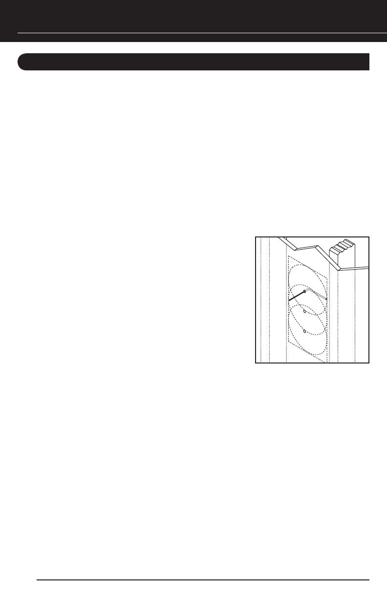
3. Cut a foot-long piece of coat hanger and bend it to create a right angle. Poke the
“L-shaped” wire into the pilot hole and turn it in a
complete circle, as shown in Figure 12
.
4.
Continue turning the coat hanger as you move it
into the cavity to a depth of approximately
4 inches. If you feel an obstruction, fill the hole(s)
with spackling compound and repeat steps
1 through 4 at a new location.
5.
If the coat hanger moves freely in a complete circle,
hold the supplied template up to the wall or ceiling
and level it in the horizontal or vertical position. Use
a pencil to outline the cutout on the surface and
then drill the four corner holes with a 1/4-inch bit
(see Figure 13 on page 17).
6.
If you are cutting drywall, use a sheetrock or keyhole saw. Cut the outline with the saw
at a 45-degree angle. That way, the drywall section can be replaced cleanly if there is
an unseen obstruction behind the wall.
7.
If you are cutting into a plaster ceiling, use masking tape to outline the penciled open-
ing and use a razor to score the plaster down to the lath beneath. Then use a chisel to
remove all of the plaster within the taped outline. To actually cut the lath, consider the
following two professional methods:
Use a saber saw with a metal cutting blade for the quickest cut. However, sawing
lath with a saber saw can easily vibrate plaster off the ceiling in a completely distant
location, thereby creating more patchwork.
If you have the patience, use a pair of tin snips to slowly nip away at the lath instead.
There is little risk with this method – it is just more time consuming.
16
Figure 12. Using a coat
hanger to check for obstructions
behind the wall speaker site.
NILES AUDIO CORPORATION 1-800-BUY-HIFI
FINISHING THE INSTALLATION
PAINTING THE GRILLE AND FRAME
After drywall is up, each HDLCR frame and grille may be painted without the need for primer. For
best results, use a spray gun or airless sprayer, thin the paint to prevent clogging of the grille holes,
and apply several light coats instead of one heavy one.
1.
Paint each grille and let it dry before installation.
2.
Paint each frame and let it dry before installation.
INSTALLING THE FRAME
1. Fill each wall cavity with insulation. Remember to use equal amounts of insulation for
each speaker.
2.
For existing construction, slip the mounting bracket through the hole and pull it toward
you so that its front edge slides into the hole and stops in place.
NOTE: FOR NEW CONSTRUCTION, THE MOUNTING BRACKET SHOULD ALREADY BE IN PLACE
(AS DESCRIBED IN THE SECTION “NEW CONSTRUCTION: INSTALLING A BRACKET” ON PAGE 14.
3. Attach each frame to its brack-
et using the supplied screws, as
shown in
Figure 13. The screws
should pull the frame and
bracket together (sandwich
-
ing the drywall) so that the
frame is absolutely flush
with the wall surface.
There should be no
gaps between the
wall and the frame.
IMPORTANT: DO NOT
OVER TIGHTEN THE
SCREWS! OVER TIGHTENING
THEM MAY MAKE
THE GRILLE DIFFICULT
TO INSTALL.
17
Figure 13. Installing the
frame into a mounting bracket.
INSTALLING A NILES MS-100 MICROSENSOR
®
1. For each speaker, locate the half-inch round, molded “IR Sensor Knockout”
on the baffle.
2.
Lay each speaker face down on a clean carpet or rug. Put the tip of a screwdriver
into the center of the round “knockout” and sharply tap the screwdriver handle
as necessary.
NOTE: TO PREVENT DAMAGE TO THE CROSSOVER NETWORK, ALWAYS REMOVE A KNOCKOUT
FROM THE REAR OF THE SPEAKER. DO NOT ATTEMPT TO REMOVE A KNOCKOUT WITH THE
SPEAKER FACE UP.
3. At each speaker, install the MS-100 (using its mounting hex nut and washer) until it is
tightly secured.
4.
Connect all MS-100 wires.
SETTING THE CTR L/R MODE
The HDLCR includes a baffle-mounted CTR L/R mode switch to optimize performance in
applications as either a center channel or left/right loudspeaker for front-channel use, as shown
in Figure 14.
For front left- or right-channel applications, slide the HDLCR’s mode switch to L/R.
For center-channel use, slide the HDLCR’s mode switch to CTR.
18
Figure 14. The HDLCR’s CTR L/R mode switch.
CTR
L/R
  • Page 1 1
  • Page 2 2
  • Page 3 3
  • Page 4 4
  • Page 5 5
  • Page 6 6
  • Page 7 7
  • Page 8 8
  • Page 9 9
  • Page 10 10
  • Page 11 11
  • Page 12 12
  • Page 13 13
  • Page 14 14
  • Page 15 15
  • Page 16 16
  • Page 17 17
  • Page 18 18
  • Page 19 19
  • Page 20 20
  • Page 21 21
  • Page 22 22
  • Page 23 23
  • Page 24 24
  • Page 25 25
  • Page 26 26
  • Page 27 27
  • Page 28 28

Niles HDLCR User manual

Category
Loudspeakers
Type
User manual

Ask a question and I''ll find the answer in the document

Finding information in a document is now easier with AI