
Installation and Servicing Instructions
Gas red condensing wall hung
combination boilers
G.C.N : 47-116-51 (24 kW)
G.C.N : 47-116-52 (30 kW)
G.C.N : 47-116-53 (38 kW)
CLAS HE
CLAS HE 24
CLAS HE 30
CLAS HE 38
The code of practice for the installation,
commissioning & servicing of central heating systems
Country of destination GB, IE

2
overview
INDEX
Overview
General Information .................................................................................................3
Advice for the Installer .............................................................................................4
CE Labelling .................................................................................................................4
Data Plate Symbols ...................................................................................................4
Safety Regulations ....................................................................................................5
Product description
Control Panel...............................................................................................................6
Display ...........................................................................................................................6
Overall View .................................................................................................................7
Overall Dimension ....................................................................................................7
Minimum Clearances ...............................................................................................7
Technical Information ..............................................................................................8
Installation
Reference Standards ................................................................................................9
Installing the Boiler ................................................................................................ 12
Gas Connection ....................................................................................................... 13
Water Connection .................................................................................................. 13
Instructions for Opening the Casing and Performing an
Internal Inspection ................................................................................................. 13
Connecting the Flue .............................................................................................. 15
Fitting the Coaxial Flue (Ø 60/100 Horizontal) ............................................. 16
Fitting the 5” Flue (Ø 80/125 Horizontal / Vertical) ..................................... 17
Fitting the Coaxial Flue (Ø 60/100 Vertical) ................................................... 18
Fitting the Twin Pipe (Ø 80/80) .......................................................................... 19
Electrical Connections .......................................................................................... 23
Peripheral Unit Connection ................................................................................ 23
Room Thermostat Connection .......................................................................... 2
4
Outdoor Sensor Connection .............................................................................. 2
4
Electrical Diagram .................................................................................................. 25
Commissioning
Initial Preparation ................................................................................................... 2
6
Electricity Supply .................................................................................................... 2
6
Filling the Heating System .................................................................................. 26
Filling of the DHW System ................................................................................... 26
Gas Supply ................................................................................................................ 26
Water Treatment ..................................................................................................... 26
First Igniton Operation ......................................................................................... 27
Ignition procedure ................................................................................................. 28
Test Function and Combustion Analysis ........................................................ 30
AUTO Function ........................................................................................................ 31
Boiler Protection Devices
Boiler Protection Devices .................................................................................... 32
Anti-Frost Device .................................................................................................... 32
Table summarising error codes ......................................................................... 32
Settings - Adjustment - Problem Identication Menus
Accessing the Menus ............................................................................................ 33
Maintenance
General Comments ................................................................................................ 41
General Access ........................................................................................................ 42
Electrical Unit ........................................................................................................... 43
Hydraulic Unit .......................................................................................................... 45
Main Heat Exchanger ............................................................................................ 53
Burner Unit ............................................................................................................... 54
Fan Unit ...................................................................................................................... 57
Gas Valve .................................................................................................................... 58
Annual Maintenance ............................................................................................. 59
Spare Parts Short List ............................................................................................ 60
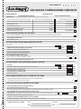
Benchmark Commissioning Checklist ............................................................ 61
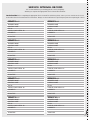
Benchmark Service Interval Record ................................................................. 62

3
overview
These instructions are suitable for CLAS HE boilers :
Do not forget the Log Book!
MTS supports Benchmark, the heating industry code to ensure the correct installation, commissioning and servicing of
domestic central heating systems.
To The Householder
Make sure you have a completed Log Book for your boiler. This provides a record of the commissioning of your boiler.
It contains important information about your particular installation that may be required by service engineers. The Log Book
will also provide contact details for the installer should you need guidance in the use of this appliance or if there are any
problems.
As with your car, your boiler will work more reliably and eciently if regularly serviced. We recommend an annual service
check. The service history of the appliance will be recorded on the Log Book.
In the unlikely event of any problems with your boiler or system you should rst contact your installer. If your installer cannot
resolve the problem he should telephone our national service helpline.
A charge may be made if MTS Service is called out to resolve a non-product related fault.
Your statutory rights are not aected.
To The Installer
As part of the commissioning of this appliance it is vital that the Log Book is completed and given to the Householder. Please ensure
that your customer is aware of the importance of keeping the Log Book safe as a record of the installation and the appliance service
history.
Please ensure that your customer is aware of the correct operation of the system, boiler and controls.
MTS recommend the use of protective clothing, when installing and working on the appliance i.e. gloves.
CUSTOMER CARE
MTS, as a leading manufacturer of domestic and commercial water heating appliances is committed to providing high quality
products and a high quality after sales service.
Advice on installation or servicing can also be obtained by contacting the MTS Technical and Customer Service Departments at High
Wycombe.
TECHNIC
AL DEPARTMENT CUSTOMER SERVICE DEPARTMENT
Tel: 0870 241 8180 Tel: 0870 600 9888
Fax: 01494 459775 Fax: 01494 459775
GUARANTEE
T
he manufacturer’s guarantee is for 2 years from the date of purchase. The guarantee is invalidated if the appliance is not installed in
accordance with the recommendations made herein or in a manner not approved by the manufacturer. To assist us in providing you
with an ecient after sales service, please return the guarantee registration card enclosed with the boiler without delay.
CAUTION
In the United Kingdom, installation, start-up, adjustments and maintenance, must be performed by a competent person only, in
accordance with the current Gas Safety (Installation & Use) Regulations and the instructions provided.
In the Republic of Ireland, the installation and initial start up of the appliance must be carried out by a Competent Person in
accordance with the current edition of I.S.813 “Domestic Gas Installations”, the current Buidling Regulations, reference should also be
made to the current ETCI rules for electrical installation.
All CORGI registered installers carry a CORGI ID card, and have a registration number. Both should be recorded in your boiler
Log Book. You can check your installer is CORGI registered by calling CORGI direct on:- (01256) 372300.
Improper installation may cause damage or injury to individuals, animals and personal property for which the manufacturer will not
be held liable. To ensure ecient and safe operation it is recommended that the boiler is serviced annually by a competent person.
If it is known that a fault exists on the appliance, it must not be used until the fault has been corrected by a competent person.
This instruction booklet is especially designed for appliances installed in the UK and the Republic of Ireland

4
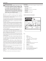
overview
CE labelling
The CE mark guarantees that the appliance conforms to the fol-
lowing directives:
- 90/396/CEE
relating to gas appliances
- 89/336/CEE
relating to electromagnetic compatibility
- 92/42/CEE
relating to energy eciency
- 73/23/CEE
relating to electrical safety
Advice for the installer
The installation and rst ignition of the boiler must be
performed by qualied personnel in compliance with
current national regulations regarding installation, and
in conformity with any requirements established by
local authorities and public health organisations.
After the boiler has been installed, the installer must
ensure that the end user receives the declaration of
conformity and the operating manual, and should
provide all necessary information as to how the boiler
and the safety devices should be handled.
This appliance is designed to produce hot water for domestic
use.
It should be connected to a heating system and a distribution
network for domestic hot water, both of which must be compatible
with its performance and power levels.
The use of the appliance for purposes other than those specied is
strictly forbidden. The manufacturer cannot be held responsible for
any damage caused by improper, incorrect and unreasonable use
of the appliance or by the failure to comply with the instructions
given in this manual.
Installation, maintenance and all other interventions must be
carried out in full conformity with the governing legal regulations
and the instructions provided by the manufacturer. Incorrect
installation can harm persons, animals and possessions; the
manufacturing company shall not be held responsible for any
damage caused as a result. The boiler is delivered in a carton. Once
you have removed all the packaging, make sure the appliance is
intact and that no parts are missing. If this is not the case, please
contact your supplier.
Keep all packaging material (clips, plastic bags, polystyrene foam, etc.)
out of reach of children as it may present a potential hazard.
In the event of a fault and/or malfunction, turn the appliance
o, turn o the gas cock and do not attempt to repair it yourself.
Contact a qualied professional instead.
Before any maintenance or repair work is performed on the boiler,
make sure you have disconnected it from the electricity supply
by switching the external bipolar switch to the “OFF” position and
removing the fuse.
All repairs, which should only be performed using original spare
parts, should be carried out by a qualied professional. Failure
to comply with the above instructions could compromise the
safety of the appliance and invalidate all liability on the part of
the manufacturer.
In the event of any maintenance or other structural work in
the immediate vicinity of the ducts or ue gas exhaust devices
and their accessories, switch the appliance o by switching the
external bipolar switch to the “OFF” position and shutting o
the gas control valve. When the work has been completed, ask a
qualied technician to check the eciency of the ducting and the
devices.
Turn the boiler o and turn the external switch “OFF” to clean the
exterior parts of the appliance.
Clean using a cloth dampened with soapy water. Do not use
aggressive detergents, insecticides or toxic products. If the
appliance is used in full compliance with current legislation, it
will operate in a safe, environmentally-friendly and cost-ecient
manner.
If using kits or optional extras, make sure they are authentic.
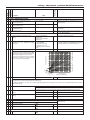
Symbols used on the data plate
Key:
1. Brand
2. Manufacturer
3. Boiler model - code
4. Serial number - certication number
5. Destination country - gas category
6. Gas setting
7. Boiler type
8. Electrical data
9. Maximum domestic hot water pressure
10. Maximum heating pressure
11. NOx class
12. Eciency
13. Max - min heat input
14. Max - min heat output
15. Max/min operating room temperature
16. Max. central heating temperature
17. Gases which may be used
MIN MAX

5
overview
Safety regulations
Key to symbols:
Failure to comply with this warning implies the risk of
personal injury, in some circumstances even fatal
Failure to comply with this warning implies the risk of
damage, in some circumstances even serious, to property,
plants or animals.
Install the appliance on a solid wall which is not subject
to vibration.
Noisiness during operation.
When drilling holes in the wall for installation
purposes, take care not to damage any electrical
wiring or existing piping.
Electrocution caused by contact with live wires. Explosions,
res or intoxication caused by gas leaking from damaged
piping. Damage to existing installations. Flooding caused
by water leaking from damaged piping.
Perform all electrical connections using wires which
have a suitable section.
Fire caused by overheating due to electrical current
passing through undersized cables.
Protect all connection pipes and wires in order to
prevent them from being damaged.
Electrocution caused by contact with live wires. Explosions,
res or intoxication caused by gas leaking from damaged
piping. Flooding caused by water leaking from damaged
piping.
Make sure the installation site and any systems to
which the appliance must be connected comply with
the applicable norms in force.
Electrocution caused by contact with live wires which
have been installed incorrectly. Damage to the appliance
caused by improper operating conditions.
Use suitable manual tools and equipment (make sure
in particular that the tool is not worn out and that its
handle is xed properly); use them correctly and make
sure they do not fall from a height. Replace them once
you have nished using them.
Personal injury from the falling splinters or fragments,
inhalation of dust, shocks, cuts, pricks and abrasions.
Damage to the appliance or surrounding objects caused
by falling splinters, knocks and incisions.
Use electrical equipment suitable for its intended use
(in particular, make sure that the power supply cable
and plug are intact and that the parts featuring rotary
or reciprocating motions are fastened correctly); use
this equipment correctly; do not obstruct passageways
with the power supply cable, make sure no equipment
could fall from a height. Disconnect it and replace it
safely after use.
Personal injury caused by falling splinters or fragments,
inhalation of dust, knocks, cuts, puncture wounds,
abrasions, noise and vibration. Damage to the appliance
or surrounding objects caused by falling splinters, knocks
and incisions.
Make sure any portable ladders are positioned
securely, that they are suitably strong and that the
steps are intact and not slippery and do not wobble
when someone climbs them. Ensure someone provides
supervision at all times.
Personal injury caused by falling from a height or cuts
(stepladders shutting accidentally).
Make sure any rolling ladders are positioned securely,
that they are suitably strong, that the steps are intact
and not slippery and that the ladders are tted with
handrails on either side of the ladder and parapets on
the landing.
Personal injury caused by falling from a height.
During all work carried out at a certain height (generally
with a dierence in height of more than two metres),
make sure that parapets are used to surround the work
area or that individual harnesses are used to prevent
falls. The space where any accidental fall may occur
should be free from dangerous obstacles, and any
impact upon falling should be cushioned by semi-rigid
or deformable surfaces.
Personal injury caused by falling from a height.
Make sure the workplace has suitable hygiene and
sanitary conditions in terms of lighting, ventilation
and solidity of the structures.
Personal injury caused by knocks, stumbling etc.
Protect the appliance and all areas in the vicinity of the
work place using suitable material.
Damage to the appliance or surrounding objects caused
by falling splinters, knocks and incisions.
Handle the appliance with suitable protection and
with care.
Damage to the appliance or surrounding objects from
shocks, knocks, incisions and squashing.
During all work procedures, wear individual protective
clothing and equipment.
Personal injury caused by electrocution, falling splinters
or fragments, inhalation of dust, shocks, cuts, puncture
wounds, abrasions, noise and vibration.
Place all debris and equipment in such a way as to
make movement easy and safe, avoiding the formation
of any piles which could yield or collapse.
Damage to the appliance or surrounding objects from
shocks, knocks, incisions and squashing.
All operations inside the appliance must be performed
with the necessary caution in order to avoid abrupt
contact with sharp parts.
Personal injury caused by cuts, puncture wounds and
abrasions.
Reset all the safety and control functions aected
by any work performed on the appliance and make
sure they operate correctly before restarting the
appliance.
Explosions, res or intoxication caused by gas leaks or an
incorrect ue gas exhaust. Damage or shutdown of the
appliance caused by out-of-control operation.
Before handling, empty all components that may contain
hot water, carrying out any bleeding if necessary.
Personal injury caused by burns.
Descale the components, in accordance with the
instructions provided on the safety data sheet of the
product used, airing the room, wearing protective
clothing, avoid mixing dierent products, and protect
the appliance and surrounding objects.
Personal injury caused by acidic substances coming into
contact with skin or eyes; inhaling or swallowing harmful
chemical agents. Damage to the appliance or surrounding
objects due to corrosion caused by acidic substances.
If you detect a smell of burning or smoke, keep clear of
the appliance, disconnect it from the electricity supply,
open all windows and contact the technician.
Personal injury caused by burns, smoke inhalation,
intoxication.

6
product description
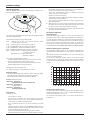
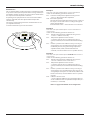
Control panel
Legend :
1. Display
2. R
eset button
3. Red indicator locking light
4.
Orange indicator C
OmfORt fonction
5. Pressure gauge
6.
Heating temperature regulation knob
7. button
_
8.
m
enu/Ok button (Programming key)
9. e
sC button
10. button +
11.
Domestic Hot Water adjustment knob
12. Time clock
13. ON/OFF button
14. Blue indicator burner ON
15.
Yellow indicator A
utO fonction
16. A
utO button (To active Thermoregulation)
17. C
OmfORt button
1
2
3
4
5
6
7
8
9
10
11
12
13
14
15
16
17
18
19
20
21
22
23
24
9
6
12
�
1
2
3
4
5
6
7
8
17
16
15
13
14
11
12
10
9

7
product description
28
770
200
150
120 120
200
180
65 6567 67
25770
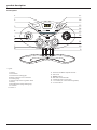
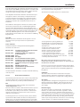
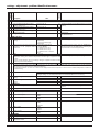
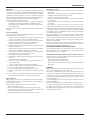
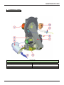
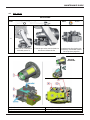
Overall view
Overall Dimensions
24/30/38
A. Central Heating Flow
B. Domestic Hot Water Outlet
C. Gas Inlet
D. Domestic Cold Water Inlet
E. Central Heating Return
450
003
003
50 50
Minimum clearances
In order to allow easy access to the boiler for
maintenance operations, The boiler must be installed
in accordance with the clearances stated below.
5
5
1
2
3
4
5
6
7
8
9
10
11
12
13
25
24
23
22
21
20
18
19
17
15
16
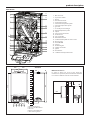
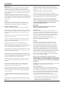
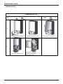
1. ue connector
2. air pressure switch
3.
burner
4. detection Electrode
5.
overheat thermostat
6.
C.H. Return temperature probe
7.
C.H. Flow temperature probe
8.
gas valve
9.
secondary heat exchanger
10.
D.H.W. temperature probe
11.
siphon
12. C.H. pressure relief valve
13. electrical box
15.
C.H. circuit lter
16.
D.H.W. Flow switch
17.
circulation Pump with air release valve
18.
diverter valve
19.
switch On-O
20. silencer
21. modulating Fan
22. ignition electrodes
23. ignitor
24. thermal fuse
25.
combustion Analysis Test Point

8
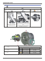
product description
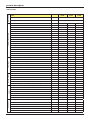
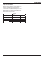
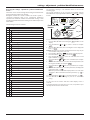
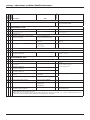
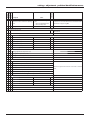
Technical Data
GENERAL NOTE
Model
24 kW
30 kW
38 kW
CE Certication (pin)
0085BR0347
Boiler type
B23-C13-C33-C43-C53-C83
POWER SPECIFICATIONS
Max/min nominal caloric ow rate (Pci) Qn
KW
22,0/5,5
28,0/6,5
31,0/7,5
Max/min nominal caloric ow rate (Pcs) Qn
KW
24,4/6,1
31,1/7,2
34,4/8,3
Domestic hot water max/min nominal caloric ow rate (Pci) Qn
KW
25,0/5,5
30,0/6,5
38,0/7,5
Domestic hot water max/min nominal caloric ow rate (Pcs) Qn
KW
27,8/6,1
33,3/7,2
42,2/8,3
Max/min power output (80°C-60°C) Pn
KW
21,6/5,2
27,4/6,2
30,3/7,3
Max/min power output (50°C-30°C) Pn
KW
23,5/6,0
30,0/6,9
33,1/8,0
Domestic hot water max/min power output Pn
KW
25,0/5,0
30,0/6,0
38,9/7,1
Combustion eciency (of ue gas)
%
97,9
97,9
98,0
Nominal caloric ow rate eciency (60/80°C) Hi/Hs
%
98,0/88,2
98,0/88,2
97,6/87,9
Nominal caloric ow rate eciency (30/50°C) (condensation) Hi/Hs
%
107,0/96,4
107,0/96,4
106,7/96,1
Eciency at 30% at 30°C (condensation) Hi/Hs
%
108,0/97,3
108,0/97,3
109,1/98,2
Eciency at 30% at 47°C Hi/Hs
%
101,0/90,9
98,2/88,4
103,1/92,8
Minimum caloric ow rate eciency (60/80°C) Hi/Hs
%
95,0/85,5
95,6/86,1
96,8/87,2
Eciency rating (dir. 92/42/EEC)
stars
****
****
****
Sedbuk class
class
A / 90,3
A / 90,3
A / 90,1
Loss when stopped (∆T = 50°C)
%
0,2
0,1
0,1
Loss of burner gas when operating
%
2,1
2,1
2,0
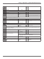
EMISSIONS
Available air pressure
Pa
137
141
132
NoX class
class
5
5
5
Flue gas temperature (G20) (80°C-60°C)
°C
63
63
63
CO2 content (G20) (80°C-60°C)
%
9,0
9,0
9,6
CO content (0%O2) (80°C-60°C)
ppm
< 100
< 100
< 125
O2 content (G20) (80°C-60°C)
%
4,5
4,5
3,5
Maximum ue gas ow (G20) (80°C-60°C)
Kg/h
41,2
49,4
59,2
Excess air (80°C-60°C)
%
27
27
20
HEATING CIRCUIT
Expansion chamber ination pressure
bar
1
1
1
Maximum heating pressure
bar
3
3
3
Expansion chamber capacity
L
6,5
6,5
6,5
Maximum water capacity with in the appliance (75°C-35°C)
L
100/300
100/300
100/300
Min/max heating temperature (high temperature range)
°C
35/82
35/82
35/82
Min/max heating temperature (low temperature range)
°C
20/45
20/45
20/45
DOMESTIC HOT WATER
CIRCUIT
Domestic hot water max/min temperature
°C
36/60
36/60
36/60
Specic ow rate of domestic hot water (∆T=30°C)
l/mn
12,0
15,0
18,2
Quantity of hot water ∆T=25°C
l/mn
14,4
18,0
21,8
Quantity of hot water ∆T=35°C
l/mn
10,3
12,9
15,6
Hot water comfort rating (EN13203)
stars
***
***
***
Hot water minimum ow rate
l/mn
< 2
< 2
< 2
Domestic hot water max/min pressure
bar
7/0,3
7/0,3
7/0,3
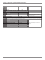
ELECTRICAL
Power supply frequency/voltage
V/Hz
230/50
230/50
230/50
Total electrical power absorbed
W
114
115
150
Minimum ambient temperature for use
°C
+5
+5
+5
Protection level for the electrical appliance
PI
X5D
X5D
X5D
Weight
kg
32
35
35,5
Dimension (L x H x D)
mm
440/820/385
440/820/455
440/820/455

9
installation
Reference Standards
In the United Kingdom, the installation and initial start-up of the
boiler must be by a CORGI registered installer in accordance with
the installation standards currently in eect, as well as with any
and all local health and safety standards i.e. CORGI.
In the Republic of Ireland the installation and initial start-up of
the appliance must be carried out by a Competent Person in
accordance with the current edition of I.S.813 “Domestic Gas
Installations” and the current Building Regulations, reference
should also be made to the current ETCI rules for electrical
installation.
The installation of this appliance must be in accordance with
the relevant requirements of the Local Building Regulations,
the current I.E.E. Wiring Regulations, the by-laws of the local
authority, in Scotland, in accordance with the Building Standards
(Scotland) Regulation and Health and Safety document No. 635,
“Electricity at Work Regulations 1989” and in the Republic of
Ireland with the current edition of I.S. 813 and the Local Building
Regulations (IE).
C.O.S.H.H.
Materials used in the manufacture of this appliance are non-
hazardous and no special precautions are required when
servicing.
Codes of Practive
Installation should also comply with the following British
Standards Code of Practice:
BS 7593:1992
Treatment of water in domestic hot water
central heating systems
BS 5546:1990 Installation of hot water supplies for
domestic purposes
BS 5440-1:2000 Flues
BS 5440-2:2000 Air supply
BS 5449:1990 Forced cicrulation hot water systems
BS 6798:2000 Installation of gas red hot water boilers
of rated input not exceeding 70kW
BS 6891:1989 Installation of low pressure gas pipes up to
28mm
BS 7671:2001 IEE Wiring Regulations
BS 4814:1990 Specication for expansion vessels
BS 5482:1994 Installation of L.P.G.
and in the Republic of Ireland in accordancce with the following
codes of practice:
I.S. 813 Domestic Gas Installations
Avoid installing the boiler where the air inlet can be polluted by
checmical products such as chlorine (swimming pool area), or
ammonia (hair dresser), or alkalin products (launderette).
Flue
Detailed information on ue assembly can be found in the
“Connecting the Flue” section.
The boiler must be installed so that the ue terminal is exposed
to the free passage of external air at all times and must not
be installed in a place likely to cause nuisance. It must not be
allowed to discharge into another room or space such as an
outhouse or closed lean-to.
Condensing boilers have a tendency to form a plume of water
vapour from the ue terminal due to the low temperature of
the ue gasses. The terminal should therefore be located with
due regard for the damage or discolouration that may occur to
building within the vicinity and consideration must also be given
to adjacent boundaries, openable windows should also be taken
into consideration when siting the ue.
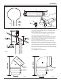
The minimum acceptable clearances are shown below:
- A Dir
ectly below an opening, window, etc 300 mm
- B Horizontally to an opening, window, etc 300 mm
- C Below gutters, soils pipes or drain pipes 75 mm
- D Below eaves 200 mm
- E From vertical drain pipe or soil pipe 75 mm
- F From internal or external corner 300 mm
- G Above ground, roof or balcony level 300 mm
- H From a surface facing the terminal 2500 mm
- I From a terminal facing a terminal 2500 mm
- J Vertically from a terminal on the same wall 1500 mm
- K Horizontally from an terminal on the same wall 300 mm
- L Fixed by vertical ue terminal
N
ote: the flue must Not be iNstalled iN a place likely to cause a
NuisaNce aNd positioNed to eNsure that products of combustioN do Not
discharge across a bouNdary
It may be necessary to protect the terminal with a guard, if this is
the case it will be necessary to purchase a stainless steel terminal
guard. Reference should be made to the Building Regulations
for guidance.
Ventilation
The room in which the boiler is installed does not require
specic ventilation. If the boiler is installed in a cupboard or
compartment ventillation is not required for cooling purposes.
Gas Supply
The gas installation and tightness testing must be in accordance
with the requirements of BS6891. Ensure that the pipe size is
adequate for demand including other gas appliances on the
same supply.
Electrical Supply
T
he appliance requires an earthed 230V - 50 Hz supply and
must be in accordance with current I.E.E. regulations. It must
also be possible to be able to completely isolate the appliance
electrically. Connection should be via a 3 amp douple pole fused
isolating switch with contact separation of at least 3mm on both
poles. Alternatively, a fused 3 Amp, 3 pin plug and unswitched
socket may be used, provided it is not used in a room containing
a bath or shower, it. It shoild only supply the appliance.

10
installation
Water Supply
The boiler is suitable for sealed systems only. The maximum
working pressure for the appliance is 6 bar. All ttings and
pipework for the appliance should be of the same standard. If
there is a possibility of the incoming mains pressure exceeding 6
bar, particularly at night, then a suitable pressure limiting valve
must be tted.
The boiler is designed to provide hot water on demand to
multiple outlets within the property. If there is a requirement for
greater demands, for example if the boiler has several bathrooms
and cloakrooms, a vented or unvented hot water storage system
may be used.
Showers
Any shower valves used with the appliance should be of a
thermostatic or pressure balanced type. Refer to the shower
manufacturer for performance guidance and suitability.
Flushing and Water Treatment
The boiler is equipped with a stainless steel heat exchanger.
The detailed recommendations for water treatment are given in
BS 7593:199
2 (Treatment of water in domestic hot water central
heating systems); the following notes are givent for general
guidance;
If the boiler is installed on an existing system, any unsuitable
additives must be removed.
Under no circumstances should the boiler be red before the
system has been thoroughly ushed; the ushing procedure
must be in line with BS 7593:199
2.
We highly recommend the use of a ushing detergent
appropriate for the metals used in the circuit. These include
cleansers produced by Fernox BetzDearbon, whose function is to
disolve any foreign matter that may be in the system;
In hard water areas or where large quantities of water are in the
system the treatment of water to prevent premature scaling of
the main exchanger is necessary.
The formation of scale strongly compromises the eciency of
the thermic exchanger because small areas of scale cause a high
increase of the temperature of the metallic walls and therefore
add to the thermal stress of the heat exchanger.
Demineralised water is more aggressive so in this situation it
is necessary to treat the water with an appropriate corrosion
inhibitor.
Any treatment of water by additives in the system for frost
protection or for corrosion inhibition has to be absolutely
suitable for all metals used in the circuit.
The use of a corrosion inhibitor in the sysem such as Fernox
MB-1, BetzDearborn Sentinel X100 or Fernox System Inhibitor
is recommended to prevent corrosion (sludge) damaging the
boiler and system;
If anti-freeze substances are to be used in the system, check
carefully that they are compatible with the metals used in the
circuit.
MTS suggests the use of suitable anti-freeze products such as
Fernox ALPHI 11, which will prevent rust and incrustation taking
place.
Preiodically check the pH balance of the water/anti-freeze
mixture of the boiler circuit and replace it when the amount
measured is out of the range stipulated by the manufacturer (7
< pH < 8).
DO NOT MIX DIFFERENT TYPES OF ANTI-FREEZE
In under-oor systems, the use of plastic pipes without
protection against penetration of oxygen through the walls can
cause corrosion of the systems metal parts (metal piping, boiler
etc), through the formation of oxides and bacterial agents.
To prevent this problem it is necessary to use pipes with an
“oxygen proof barrier”, in accordance with standards DIN
47
26/4729. If pipes of this kind are not used, keep the system
separate by installing heat exchangers of those with a
specic system water treatment.
IMPORTANT
Failire to carry out the water treatment procedure will
invalidate the appliance guarantee.
System Controls
The boiler is electrically controlled and is suitable for most
modern electronic time and temperature controls. The addition
of such external controls can be benecial to the ecient
operation of the system. The boiler connections for external
c
ontols are 12V DC and so only controls of 12V DC that have
voltage free contacts should be used. (page 24).
MTS supply a range of wired and wireless system controls.
Contact your supplier for more details.
Location
The boiler can be installed on any suitable internal wall
(suitable sound proong may be required when installing
onto a stud partition wall). Provision must be made to allow
for the correct routing of the ue and siting of the terminal
to allow the safe and ecient removal of the ue products. A
compartment or cupbaord may be used provided that it has
been built or modied for this purpose. It is not necessary to
provide permanent ventillation for cooling purposes. Detailed
r
ecommendations are given in BS 5440 Part 2. If it is proposed
that it is to be installed in a timber framed building then
r
eference should be made to British Gas Document DM2, IGE/
UP/7 or advice sought from CORGI.
Where a room sealed appliance is installed in a room
containing a bath or shower, the appliance and any electrical
switch or appliance control, utilising mains electricity should
be situated specically in accordance with current IEE Wiring
Regulations.
For unusual locations, special procedures may be necessary. BS
6798:2000 gives detailed guidance on this aspect.
Codensate Discharge
The condensate discharge hose from the boiler must have a
c
ontinuous fall of 2.5
o
and must be inserted by at least 50mm
into a suitable acid resistant pipe - e.g. plastic waste or overow
pipe. The condensate discharge pipe must have a minimum
diamet
er of 22mm, must have a continuous fall and preferably
be installed and terminated to prevent freezing.
The discharge pipe must be terminated in a suitable position:
i)
Connecting into an internal soil stack (at least 450mm above
the invert of the stack). A trap giving a water seal of at least
75mm must be inc
orporated into the pipe run, there also
must be an air beak upstr
eam of the trap.

11
installation
ii) Connecting into the waste system of the building such as a
washing maching or sink trap. The connection must be
upstr
eam of the washing machine/sink. If the connection
is down stream of if the waste trap then an additional trap
giving a minimum water seal of 75mm and an air break must be
incorporated in the pipe run, as above.
iii)
Terminating into a gully, below the grid level but above the
w
ater level
iv) Into a soakaway
Note: If any condensate pipework is to be installed externally
then it should be kept to a minimum and be insulated with a
waterproof insulation and have a continuous fall. The total length
of external pipe used should not exceed 3 metres.
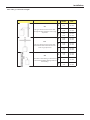
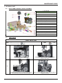
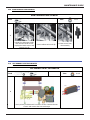
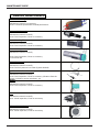
Some examples of the type of condensate terminations can be
found below.
1. Internal termination of codensate drainage pipe to internal
stack.
2
. External terminaton of condensate drainage pipe via internal
discharge branch (e.g. sink waste) and condensate siphon.
3. External termination of condensate drainage pipe via internal
discharge branch (e.g. sink waste - proprietary tting).
4. External termination of condensate drainage pipe via
condensate siphon

12
installation
Installing the Boiler
Please check that you are familiar with the installation
requirement before commencing work (pages 7 - 11).
The installation accessories described in the following list are
included in the boiler packaging:
-
Hanging bracket
- A paper template (showing the dimensions of the boiler with
5 mm side clear
ances)
- Connection valves (Compression)
- Screws and washers
- Filling loop
- Installation, Servicing and Operating Instructions
- Flue gasket
Method of positioning the boiler on the wall
The paper template can be used to ensure the correct
positioning of kitchen cabinets etc.
The paper template has to be xed to the wall and used to locate
the position of the hanging bracket and the centre for the ue
hole.
Drill and plug the wall and secure the hanging bracket using
the screws provided. Remove the boiler from it’s packaging and
remove the front casing panel.
Place the boiler on the hanging bracket.
N
ote: the appliaNce must Not be fitted oN a combustible wall surface.
Connecting the Boiler to the System
-
Remove the boiler casing as described on page 13;
- Remove the caps and connect the valves to the boiler using
the w
ashers provided;
- 4 x bre washers for the CH ow and return, cold water inlet
and hot w
ater outlet connections;
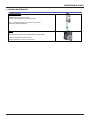
Safety Valve Discharge and Condense Outlet
The pressure relief valve tube is made of copper. It should
terminate below the boiler safely outside the premises. Care
should be taken that it does not terminate over an entrance or
window or where a discharge of heated water could endanger
occupants or passers by.
Fill the central heating and DHW system and bleed air from the
system as described in the Commissioning instructions (page
2
6).
The system should be carefully checked for leaks, as frequent
relling could cause premature system corrosion or unnecessary
scaling of the heat exchanger. The pipe from the trap should be
connected to a drain as described in the relevant regulations.
Pay special attention not to bend the condensate silicone drain
pipe is such a way as to interrupt the ow. Please only use drain
pipe material compatible with condensate products (refer to BS
6798:
2000).
The condensate ow can reach 2 litres/hour because of the
acidity of the condensate products (Ph close to 2), take care
before operation.
See page 11 for condensate discharge possibiities.
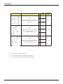
Note: Connections viewed from behind boiler
A
A
- remove the 2 screws A from the transport bar
- dispose of the transport bar and reassemble
the xing screws.

13
installation
Gas connection
Make sure, using the labels on the packaging and the data plate
on the appliance itself, that the boiler is in the correct country
and that the gas category for which the boiler was designed
corresponds to one of the categories available in the country
where it will be used.
The gas supply piping must be created and measured out in
compliance with specic legal requirements and in accordance
with the maximum power of the boiler; you should also make sure
that the shut-o valve is the right size and that it is connected
correctly.
Check that the supplied gas corresponds to the type of gas for
which the boiler was designed (see the data plate located on the
appliance itself).
It is also important to check that the pressure of the gas (methane
or LPG) you will be using to feed the boiler is suitable, because if it
is insucient the power may be reduced, causing inconvenience
for the user.
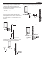
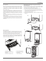
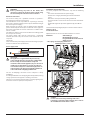
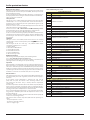
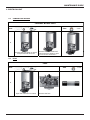
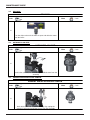
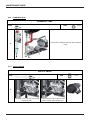
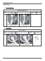
Instructions for opening the casing and performing an
internal inspection
Before performing any work on the boiler, rst disconnect it from
the electrical power supply using the external bipolar switch
removing the fuse and shutting o the gas valve.
To access the inside of the boiler, the following is necessary:
1. Remove the casing by unhooking it from the control panel (a)
2. Loosen the two screws on the front casing (b), pull it forwards
and unhook it from the upper pins (c)
3.
Lower the control panel (d)
4. Unhook the two clips on the combustion chamber panel and
lift o (e).
(c)
(b)
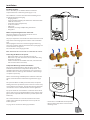
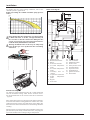
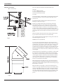
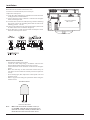
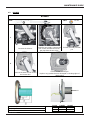
Water connection
The illustration shows the connections for the water and gas
attachments of the boiler. See valves conguration on page 13.
Check that the maximum water mains pressure does not exceed 6
bar; if it does, a pressure reducing valve must be installed.
For the measuring of the pipes and of the heating bodies in the
heating system, the residual head value should be calculated as a
function of the requested ow rate, in accordance with the values
shown in the circulation pump graph.
A.
Central heating Flow E. Central Heating Return
B
. Domestic Hot Water Outlet F. Safety Valve Discharge
C.
Gas Inlet H. Drain Valve
D
. Domestic Cold Water Inlet I. Drain condensate
(d)
(a)
(e)
A
B
C
D
E
I
H
F

14
installation
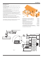
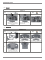
To calculate the size of the heating installation, refer to the
"Available pressure" graph below.
Graph representing the available circulation pump pressure
ΔT20
o
C
Before the rst time the equipment is used, the trap must
be lled with water. To do this, add approximately 1/4
litre of water via the ue outlet before tting the ue
system, or unscrew the cap on the trap positioned under-
neath the boiler, ll it with water and ret it
Warning! insucient water in the trap can temporarily
cause the ue gas to be expelled into the surrounding
ambient air
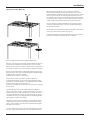
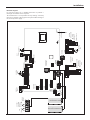
Water circuit diagram
0
50
100
150
200
250
300
350
400
450
500
0 100 200 300 400 500 600 700 800 900 1000 1100 1200
mbar
l/h
24 kW
30-35 kW
A
B
C
D
E
I
G
H
F
2
1
4
3
11
8
10
9
12
13
14
15
16
17
18
19
20
21
22
7
6
5
A B C D E
1. Manual air vent
2. Overheat thermostat
3.
Burner
4.
Detection electrode
5.
C.H. ow temperature
probe
6.
C.H. return temperature
probe
7.
Secondary heat ex-
changer
8.
C.H. pressure relief valve
9. D.H.W. temperature
probe
10.
By-pass
11. Drain valve
1
2. Condensate trap
14. C.H. circuit lter
15.
D.H.W. Flow switch
16.
diverter valve
17.
water pressure sensor
18.
circulation Pump
19.
expansion vessel
20. modulating Fan
21. ignition electrodes
22. thermal fuse
Underoor heating
For appliances with underoor heating, t a safety thermostat
onto the underoor heating outlet. For the electrical connec-
tion of the thermostat see the section on “Electrical connections
- page
24”.
If the outlet temperature is too high, the boiler will stop both do-
mestic hot water and the heating production and the error code 1
16 “oor thermostat contact open” will appear on the display. The
boiler will restart when the thermostat is closed during automatic
resetting.
If the thermostat cannot be installed, the underoor heating equi-
pment must be protected by a thermostatic valve, or by a by-pass
to prevent the oor from reaching too high a temperature.
30-38 kW

15
installation
Connecting the Flue
Flue System
The provision for satisfactory ue termination must be made as
described in BS 5440-1.
The appliance must be installed so that the ue terminal is expo-
sed to outdoor air.
The terminal must not discharge into another room or space
such as an outhouse or lean-to.
It is important that the position of the terminal allows a free
passage of air across it at all times.
The terminal should be located with due regard for the damage
or discolouration that might occur on buildings in the vicinity, it
must also be located in a place not likely to cause nuisance.
In cold or humid weather water vapour may condense on leaving
the ue terminal.
The eect of such “steaming” must be considered.
If the terminal is less than 2 metres above a balcony, above
ground or above a at roof to which people have access, then a
suitable stainless steel terminal guard must be tted.
The minimum acceptable spacing from the terminal to obstruc-
tions and ventilation openings are specied in Fig. 1.
- A Directly below an opening, window, etc 300 mm
- B Horizontally to an opening, window, etc 300 mm
- C Below gutters, soils pipes or drain pipes 75 mm
- D Below eaves 200 mm
- E From vertical drain pipe or soil pipe 75 mm
- F From internal or external corner 300 mm
- G Above ground, roof or balcony level 300 mm
- H From a surface facing the terminal 2500 mm
- I From a terminal facing a terminal 2500 mm
- J Vertically from a terminal on the same wall 1500 mm
- K Horizontally from an terminal on the same wall 300 mm
- L Fixed by vertical ue terminal
118 mm
See table
118 mm
4
See table on page 21
Fig. 2
Fig. 1
180

16
installation
Warning
The exhaust gas ducts must not be in contact with or close to
inammable material and must not pass through building struc-
tures or walls made of inammable material.
When replacing an old appliance, the ue system must be chan-
ged.
Important
Ensure that the ue is not blocked.
Ensure that the ue is supported and assembled in accordance
with these instructions.
150 mm
118
* pente 5 mm par mètre
150 mm
* pente
Installation without extension
Installation with extension
slope 5 mm per metre
Level
Level
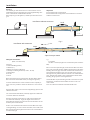
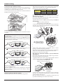
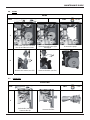
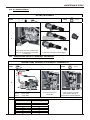
Fitting the Coaxial Flue
(Ø 60 / 100 Horizontal)
Contents:
1x Silicone O-Ring (60mm)
1x Elbow (90°)
2x Wall Seals (Internal & External)
1x Flue Pipe including Terminal (1 metre - 60/100)
2x Flue Clamps
4x Screws
2x Seals
Once the boiler has been positioned on the wall, t the rubber
ue seal into the internal ue turret (see diagram opposite),
insert the elbow into the socket and rotate to the required po-
sition. note: It is possible to rotate the elbow 360° on its vertical
axis.
Using the ue clamp, seals and screws supplied (Fig 4) secure the
elbow to the boiler.
The 1 metre horizontal ue kit (3318073) supplied is suitable for
an exact X dimension of 753mm.
Measure the distance from the face of the external wall to the
face of the ue elbow (X - Fig 2), this gure must now be su-
btracted from 753mm, you now have the total amount to be cut
from the plain end of the ue.
Draw a circle around the outer ue and cut the ue to the requi-
red length taking care not to cut the inner ue, next cut the inner
ue ensuring that the length between the inner and outer ue is
maintained. (Fig 4).
e.g.
X = 555mm
753-555 = 198mm (Length to be cut from the plain end of the
ue).
Once cut to the required length, ensure that the ue is free from
burrs and reassemble the ue. If tting the ue from inside of the
building attach the grey outer wall seal to the ue terminal and
push the ue through the hole, once the wall seal has passed
through the hole, pull the ue back until the seal is ush with the
wall. Alternatively, the ue can be installed from outside of the
building, the grey outer seal being tted last.
Should the ue require extending, the ue connections are push
t, however, one ue bracket should be used to secure each
metre of ue.
Note: See table for maximum and minimum ue runs.
slope
Fig. 3

17
installation
Clamp
Seal
Screws
Fitting the 5” Flue
(Ø 80 / 125 Horizontal/vertical)
Once the boiler has been positioned on the wall, it is necessary
to insert the Ø80/125 adaptor (Fig. 5) for both horizontal and
vertical ue runs into the boiler ue socket (not supplied with
ue kit - Part No 3318095).
Push the adaptor onto the boilers ue connection, grease the
seals then add extensions or elbows as required, secure the
adaptor, using the clamp and screws provided.
To t extensions or elbows it is rst necessary to ensure that the
lip seal is tted correctly into the inner ue, once veried, it is
simply necessary to push them together, no clamps are neces-
sary to secure the ue components.
Before proceeding to t the ue, ensure that the maximum
ue length has not been exceeded (See the tables) and that all
elbows and bends have been taken into consideration, the ma-
ximum ue length is 10 metres, for each additional 90° elbow 1
metre must be subtracted from the total ue length, and for each
45° 0.5 metres must be subtracted from the total ue length (the
height of the vertical adaptor and a 45° bend can be seen in Fig.6
and a 90° bend in Fig. 7).
Note: DO NOT cut the vertical ue kit.
180 mm
Fig. 4
Fig. 5
Fig. 6 Fig. 7

18
installation
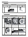
Fitting the Coaxial Flue
(Ø 60 / 100 Vertical)
Note: See table for maximum and minimum ue runs.
Contents:
1x Silicone O-Ring (60mm)
1x Conical Adaptor (60/100mm)
1x Vertical Flue Kit (80/125mm)
3x Screws
The vertical ue kit is supplied with a specially designed weather
proof terminal tted, it can be used either with a at roof or a
pitched roof.
The Vertical ue kits useable lengths with the pitched roof
ashings are indicated in Fig. 7.
Before proceeding to t the ue, ensure that the maximum
ue length has not been exceeded (See the tables) and that
all elbows and bends have been taken into consideration, the
maximum ue length is see table, for each additional 90° elbow
1 metre must be subtracted from the total ue length, and for
each 45° 0.5 metres must be subtracted from the total ue length
(the height of the vertical adaptor and a 45° bend can be seen in
Fig. 8).
Mark the position of the ue hole in the ceiling and/or roof (see
Fig. 7 for distance from wall to the centre of the ue).
Cut a 130mm diameter hole through the ceiling and/or roof and
t the ashing plate to the roof.
DO NOT cut the vertical ue kit.
To connect the vertical ue kit directly to the boiler, place the
vertical starter kit (Part No. 3318079) (see Fig. 7) onto the exhaust
manifold and secure with the clamp, t the vertical adaptor onto
the vertical starter kit (note: there is no need to use a clamp to
secure this as it is a push t connection), the vertical ue kit must
then be inserted through the roof ashing, this will ensure that
the correct clearance above the roof is provided as the terminal is
a xed height.
Should extensions be required, they are available in 1 metre (Part
No. 3318077), 500mm (Part No. 3318078) and 160mm lengths,
they must be connected directly to the vertical starter kit before
connecting the adaptor to allow the vertical ue kit to be tted.
In the event that extension pieces need to be shortened, they
must only be cut at the male end and it must be ensured that
the inner and outer ue remain ush.
When utilising the vertical ue system, action must be taken to
ensure that the ue is supported adequately to prevent the wei-
ght being transferred to the appliance ue connection by using 1
ue bracket per extension.
When the ue passes through a ceiling or wooden oor, there
must be an air gap of 25mm between any part of the ue system
and any combustible material. The use of a ceiling plate will faci-
litate this. Also when the ue passes from one room to another
a re stop must be tted to prevent the passage of smoke or re,
irrespective of the structural material through which the ue
passes.
180 mm
Fig. 7
Fig. 8

19
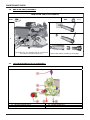
installation
Fitting the Twin Pipe (Ø80 / 80)
Note: See table for maximum and minimum ue runs.
Where it is not possible to terminate the ue within the distance
permitted for coaxial ues, the twin ue pipe can be used by
tting a special adaptor to the ue connector and using the aper-
ture for the air intake located on top of the combustion chamber.
Always ensure that the ue is adequately supported, using one
ue bracket per extension and avoiding low points. (MTS supply
suitable clamps as Part No. 705778).
To utilise the air intake it is necessary to:
1) Take the air intake cover o the top of the appliance
2
) Assemble the ange on the header supplied with the boiler
3) Insert the header on the tube or the elbow up until the lower
stop (you do not have to use the washer).
4) Insert the elbow/header in the boiler air intake hole and fasten
it with screws.
The twin ue pipes can be tted with or without additional
elbows and need no clamps, simply ensure that the red o-ring is
inserted in the female end of the ue pipe and push the exten-
sion piece fully into the previous section of ue pipe or elbow,
check that the o-ring is not dislodged when assembling the ue
(greasing the seal will aid assembly).
Twin pipe can also be converted back to Coaxial ue to enable
vertical termination with a coaxial kit by using the pipe bridge
(Twin - Coaxial Adaptor - Part No. 3318089). When running the
twin ue pipe vertically.
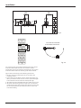
It is not possible to terminate concentrically horizontally. Termi-
nation is only possible with separate air and exhaust terminals.
When siting the twin ue pipe, the air intake and exhaust
terminals must terminate on the same wall, the centres of the
t
erminals must be a minimum of 280 mm apart and the air intake
must not be sited above the exhaust terminal (refer to Fig. 10).
The air intake pipe can be run horizontally, however, the terminal
and the nal 1 metre of ue must be installed either horizontally
or with a slight fall away from the boiler to avoid rain ingress.
It is also strongly recommended that the air intake pipe run be
constructed of insulated pipe to prevent condense forming on
the outside of the tube.
The maximum permissible ue length for twin ue is dependent
on the t
ype of run used (see table on page 21).
For further information relating to ue runs not illustrated, please
c
ontact the Technical Department on 0870 241 8180.

20
installation
For coaxial systems, the maximum development value, mentio-
ned in the table below also takes into account an elbow.
For twin ue systems the maximum development value, mentio-
ned in the table includes the exhaust gas/air intake terminal.
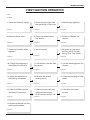
Type 5 outlets should respect the following instructions:
1- Use the same ø 80 mm ue pipes for the air intakes and
exhaust gas ducts.
2- If you need to insert elbows in the air intake and exhaust gas
ducts, you should consider for each one the equivalent length
to be included in the calculation of developed length.
3- The exhaust gas duct should jut above the roof by at least 0.5 m.
4- The intake and exhaust gas ducts in Type C13 + C53 must be
installed on the same wall, or where the exhaust is vertical and
the air intake horizontal, the terminals must be on the same
side of the building.
EXHAUST
AIR INTAKE
AIR INTAKE
AIR INTAKE MUST NOT BE
FITTED ABOVE THE EXHAUST
195
105
120
180
Fig. 9
Fig. 10
Page is loading ...
Page is loading ...
Page is loading ...
Page is loading ...
Page is loading ...
Page is loading ...
Page is loading ...
Page is loading ...
Page is loading ...
Page is loading ...
Page is loading ...
Page is loading ...
Page is loading ...
Page is loading ...
Page is loading ...
Page is loading ...
Page is loading ...
Page is loading ...
Page is loading ...
Page is loading ...
Page is loading ...
Page is loading ...
Page is loading ...
Page is loading ...
Page is loading ...
Page is loading ...
Page is loading ...
Page is loading ...
Page is loading ...
Page is loading ...
Page is loading ...
Page is loading ...
Page is loading ...
Page is loading ...
Page is loading ...
Page is loading ...
Page is loading ...
Page is loading ...
Page is loading ...
Page is loading ...
Page is loading ...
Page is loading ...
Page is loading ...
Page is loading ...
-
 1
1
-
 2
2
-
 3
3
-
 4
4
-
 5
5
-
 6
6
-
 7
7
-
 8
8
-
 9
9
-
 10
10
-
 11
11
-
 12
12
-
 13
13
-
 14
14
-
 15
15
-
 16
16
-
 17
17
-
 18
18
-
 19
19
-
 20
20
-
 21
21
-
 22
22
-
 23
23
-
 24
24
-
 25
25
-
 26
26
-
 27
27
-
 28
28
-
 29
29
-
 30
30
-
 31
31
-
 32
32
-
 33
33
-
 34
34
-
 35
35
-
 36
36
-
 37
37
-
 38
38
-
 39
39
-
 40
40
-
 41
41
-
 42
42
-
 43
43
-
 44
44
-
 45
45
-
 46
46
-
 47
47
-
 48
48
-
 49
49
-
 50
50
-
 51
51
-
 52
52
-
 53
53
-
 54
54
-
 55
55
-
 56
56
-
 57
57
-
 58
58
-
 59
59
-
 60
60
-
 61
61
-
 62
62
-
 63
63
-
 64
64


Ask a question and I''ll find the answer in the document
Finding information in a document is now easier with AI
Related papers
-
Ariston Clas Net One Owner's manual
-
-
-
-
-
-
-
-
-
Other documents
-
Potterton Performa 24 Installation And Servicing Instructions
-
Baxi Combi Instant 80 HE Quick start guide
-
ICI Caldaie SOLAR SYSTEM C 31 User manual
-
Chaffoteaux & Maury Centora green Maintenance And Service Manual
-
 Ravenheat CS 80 T Instructions For Use Installation And Servicing
-
Gledhill Combination Boiler Owner's manual
-
Lochinvar CP-M+80 Installation, Commissioning & Maintenance Instructions
-
 Biasi GARDA M90F.28S User manual
-
-
IDEAL INDUSTRIES C24 User manual

