IDEAL INDUSTRIES 61-310 User manual
- Category
- Multimeters
- Type
- User manual
This manual is also suitable for
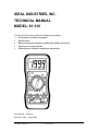
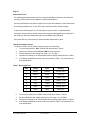
IDEAL INDUSTRIES 61-310 is a digital multimeter designed to perform a range of electrical measurements, including voltage, current, resistance, diode check, continuity, and temperature. With its 3 1/2 digit LCD display, it provides clear and precise readings. The meter features automatic power-off to conserve battery life and a data hold function to freeze readings on the display. Its compact size and rugged construction make it suitable for various applications, from basic electrical testing to troubleshooting and repair.
IDEAL INDUSTRIES 61-310 is a digital multimeter designed to perform a range of electrical measurements, including voltage, current, resistance, diode check, continuity, and temperature. With its 3 1/2 digit LCD display, it provides clear and precise readings. The meter features automatic power-off to conserve battery life and a data hold function to freeze readings on the display. Its compact size and rugged construction make it suitable for various applications, from basic electrical testing to troubleshooting and repair.


-
 1
1
-
 2
2
-
 3
3
-
 4
4
-
 5
5
-
 6
6
-
 7
7
-
 8
8
-
 9
9
-
 10
10
-
 11
11
-
 12
12
-
 13
13
-
 14
14
-
 15
15


IDEAL INDUSTRIES 61-310 User manual
- Category
- Multimeters
- Type
- User manual
- This manual is also suitable for
IDEAL INDUSTRIES 61-310 is a digital multimeter designed to perform a range of electrical measurements, including voltage, current, resistance, diode check, continuity, and temperature. With its 3 1/2 digit LCD display, it provides clear and precise readings. The meter features automatic power-off to conserve battery life and a data hold function to freeze readings on the display. Its compact size and rugged construction make it suitable for various applications, from basic electrical testing to troubleshooting and repair.
Ask a question and I''ll find the answer in the document
Finding information in a document is now easier with AI
Related papers
Other documents
-
Triplett BBT858L User manual
-
UNI-T UT202A Operating instructions
-
-
Traceable 3250 Owner's manual
-
Milwaukee 2206-20 Repair Service Instructions
-
Actron CP7674 Features Chart
-
UNI-T UT201 Specification
-
Radio Shack 22-178 Owner's manual
-
 Wavetek Meterman 5XL 10XL 15XL 16XL User manual
-
BK Precision 2831D User manual
