Yamaha CD8-mLAN User manual
- Category
- Musical Instruments
- Type
- User manual
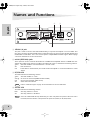
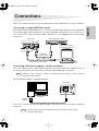
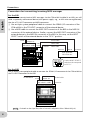
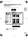
Yamaha CD8-mLAN is an interface card that provides mLAN interfacing. mLAN is a digital network designed for music and based on the IEEE 1394 high performance serial bus. It makes it easy to construct sophisticated networks for audio and MIDI signals that can be re-configured without changing the physical cabling. The CD8-mLAN adds two mLAN connectors to the Yamaha 02R or 03D digital recording consoles.
Yamaha CD8-mLAN is an interface card that provides mLAN interfacing. mLAN is a digital network designed for music and based on the IEEE 1394 high performance serial bus. It makes it easy to construct sophisticated networks for audio and MIDI signals that can be re-configured without changing the physical cabling. The CD8-mLAN adds two mLAN connectors to the Yamaha 02R or 03D digital recording consoles.


-
 1
1
-
 2
2
-
 3
3
-
 4
4
-
 5
5
-
 6
6
-
 7
7
-
 8
8
-
 9
9
-
 10
10
-
 11
11
-
 12
12


Yamaha CD8-mLAN User manual
- Category
- Musical Instruments
- Type
- User manual
Yamaha CD8-mLAN is an interface card that provides mLAN interfacing. mLAN is a digital network designed for music and based on the IEEE 1394 high performance serial bus. It makes it easy to construct sophisticated networks for audio and MIDI signals that can be re-configured without changing the physical cabling. The CD8-mLAN adds two mLAN connectors to the Yamaha 02R or 03D digital recording consoles.
Ask a question and I''ll find the answer in the document
Finding information in a document is now easier with AI
Related papers
-
Yamaha MIM1D Owner's manual
-
-
PRESONUS FIREstation Owner's manual
-
-
-
-
-
-
-
Other documents
-
PRESONUS FIREstation Owner's manual
-
Alesis 03D User manual
-
-
-
Korg Triton Studio User manual
-
Cyrus CD6 & CD8 Owner's manual
-
-
-
-