Acson A4LC Troubleshooting guide
- Category
- Remote controls
- Type
- Troubleshooting guide

SERVICE
GUIDE BOOK

ACSON Service Guide Book
1
Table of Contents
1.0 Model Name
1.1 Product Name Description
...............................
2
1.2 Nomenclature
...............................
3
2.0 Conversion Table
2.1 Conversion Table
...............................
5
3.0 Product Mainboard vs. Handset Matrix
3.1 Product Mainboard vs. Handset Matrix
...............................
6
4.0 Controller Development History
4.1 Controller Development History
...............................
8
5.0 Handset Operating Guide
5.1 G6
...............................
10
5.2 G8
...............................
12
5.3 G12
...............................
14
5.4 G18
...............................
16
5.5 GS02
...............................
18
5.6 APJ2
...............................
21
5.6 SLM3
...............................
24
5.7 Sequential LCD
...............................
26
5.8 Netware 3
...............................
28
6.0 Controller Configuration
6.1 Auto Random Restart
...............................
30
6.2 Hot Keep Selection
...............................
31
6.3 Auxiliary Heater Conversion
...............................
33
6.4 Multi Split Conversion
...............................
36
6.5 Sequential Controller
...............................
37
6.6 Chilled Water Fan Coil Unit – W1V
...............................
42
6.7 Chilled Water Fan Coil Unit – W2.0
...............................
43
6.8 U1.5
L208A Conversion
...............................
44
6.9
WMF U1.4 to L2EF Conversion
...............................
45
7.0 Service Diagnosis
7.1 Self Diagnosis Table
...............................
46
7.2 General Check
...............................
80
7.3 General Troubleshooting Guide
...............................
81
Appendix
Resistance – Temperature Characteristic
...............................
88

ACSON Service Guide Book
2
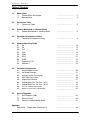
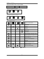
1.0 Model Name
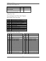
1.1 Product Name Description
No. Description Generic Model Name ACSON Brand
1 Wall Mounted Fan Coil Unit WM / 5WM AWM / A5WM
2 Wall Mounted AC Inverter Fan Coil Unit WMV AWMV
3 Wall Mounted DC Inverter Fan Coil Unit 5WMX A5WMX
4 Wall Mounted DC Inverter-Y Fan Coil Unit 5WMY A5WMY
4 Ceiling Exposed Fan Coil Unit CE / 5CE RCM / R5CM
5 Ceiling Cassette Fan Coil Unit CK / 5CK ACK / A5CK
6 Ceiling Concealed Fan Coil Unit CC / 5CC ACC / A5CC
7 Ducted Split Blower Unit SB ADB
8 Chilled Water Fan Coil Unit CW ACW
9 Water Source Heatpump Split Unit WSS / 5WSS AWSS / A5WSS
10 Horizontal Water Source Heatpump Unit WH AWH
11 Air Cooled Mini Chiller AC / 4AC / 5AC AMAC / A4MAC / A5MAC
12 Single Split Condensing Unit SL / 4SL / 5SL ALC / A4LC / A5LC
13 Single Split AC Inverter Condensing Unit SLV ALCV
14 Single Split DC Inverter Condensing Unit 5SLX A5LCX
15 Single Split DC Inverter Condensing Unit 5SLY A5SLY
15 Modular Split Condensing Unit MSS / 4MSS AMC / A4MC
16 Multi Split Series MSD / 4MSD AMSD / A4MSD
MST / 4MST AMST / A4MST
MSH AMSH
17 Multi Split AC Inverter Condensing Unit MSV AMSV
18 Multi Split DC Inverter Condensing Unit 5MSX A5MSX
19 Multi Split DC Inverter Condensing Unit 5MSY A5MSY
20 Multi Digital Scroll Units MDS/ 5MDS AMDS/ A5MDS
21 Horizontal Condensing Unit HDC / 5HDC AHDC / A5HDC
22 Vertical Condensing Unit VCU AVCU
23 Air Cooled Roof Top Packaged Air
Conditioner
RT / 4RT ART / A4RT
24 Air Cooled Inverter Mini Chiller 5ACV A5ACV

ACSON Service Guide Book
3
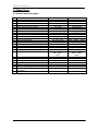
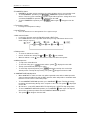
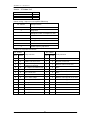
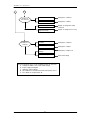
1.2 Nomenclature
Indoor Unit
-
Electrical
A : 220-240V/1Ph/50Hz
F : 380
-
415V/3Ph/50Hz
Product Specifications Variation
AA : Revision
Connection Type
F : Flare
X : Not Applicable
Model Name
WM : Wall Mounted
CK : Ceiling Cassette
Series
G : G Series
Piping
H : 4 Pipes System
Omitted if 2 pipes system
Capacity
10 : 10,000 Btu/h
Brand
A : Acson
Model Type
R : Heat Pump
W : Chilled Water Fan Coil
Omitted if DX Cooling Only
Refrigerant
5 : R410A
Omitted if R22
A WM
Inverter Series
X: X-Series
Y: Y-Series
Omitted if Non
-
inverter
10 G W
A X A A

ACSON Service Guide Book
4
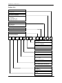
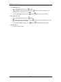
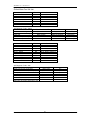
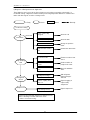
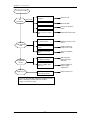
Outdoor Unit
Electrical
A : 220-240V/1Ph/50Hz
F : 380-415V/3Ph/50Hz
Market Region
C : Export with CE mark
Compressor
P : Panasonic
M : Mitsubishi
Specifications Variation
O : Standard Unit
I : Gold Fins
G : Low Ambient Unit
H : High Ambient Unit
Others
A : First Issue
Model Name
LC : Single Split Condensing Unit
MC : Modular Split Condensing Unit
Capacity
10 : 10,000 Btu/h
Model Type
R : Heat Pump
Omitted if Cooling Only
Series
C : C Series
Brand
A : Acson
Refrigerant
5 : R410A
Omitted if R22
A LC 10 C R
-
A C P O A
Inverter Series
X : X - series
Y : Y – series
Omitted if non
-
invert
er

ACSON Service Guide Book
5
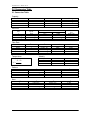
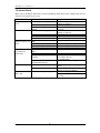
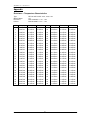
2.0 Conversion Table
2.1 Conversion Table
Capacity
Btu/hr MBH kCal/Hr kW
1 0.001 0.252 0.293 x 10
-3
1000 1 252 0.293
3.968 0.004 1 1.162 x 10
-3
3412 3.412 860.04 1
Pressure
W.G. Pascal
PSI kg/cm
2
(in.) (ft.) (Pa)
1 0.07 27.7 2.309 0.69 x 10
4
14.22 1 394.08 32.84 9.81 x 10
4
3.61 x 10
-2
2.538 x 10
-3
1 0.083 248.84
1.45 x 10
-4
0.1 x 10
-4
0.004 3.349 x 10
-4
1
Flow Rate
L/s m
3
/hr m
3
/s U.S. GPM CFM
1 3.6 0.001 15.85 2.119
0.278 1 0.278 x 10
-3
4.403 0.588
1000 3600 1 15850 2119
0.063 0.227 0.063 x 10
-3
1 0.1337
0.472 1.7 0.472 x 10
-3
7.481 1
Temperature Velocity
fps m/s fpm
1 0.305 60
3.281 1 196.9
0.017 0.005 1
Volume
L m
3
U.S. G.P.M. ft
3
1 0.001 0.264 0.0353
1000 1 264 35.3
3.785 3.785 x 10
-3
1 0.134
28.315 0.028 7.48 1
Area
in
2
ft
2
m
2
cm
2
1 6.94 x 10
-3
6.452 x 10
-4
6.452
144 1 0.093 929.03
1550.06 10.764 1 1 x 10
4
0.155 1.076 x 10
-3
1 x 10
-4
1
°F = (18 x °C) + 32
8
.
1
32
−
°
=°
F
C

ACSON Service Guide Book
6
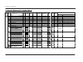
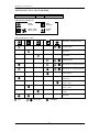
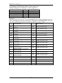
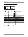
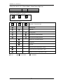
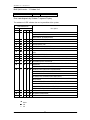
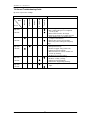
3.0 Product Mainboard vs. Handset Matrix
Handset
Type
No.
Main Board (IC)
Model
L2.0
L2GSN
L208A
W_2_03A
U1SB125
2P206569-4 SQ2.0
VA2.0
VA3.0
Standard Optional
1 WM - F Series
G18 SLM3 + AC5300 / Netware 3
2 WM - G Series
G18 SLM3 + AC5300 / Netware 3
3 WMS - G Series
G18 SLM3 + AC5300 / Netware 3
4 WM – J Series
G18 -
5 CK - A/B/C/E Series
G18 SLM3 + AC5300 / Netware 3
6 CE - D Series
G18 SLM3 + AC5300 / Netware 3
7 CE - E Series
G18 SLM3 + AC5300 / Netware 3
8 CC - C Series
SLM3 Netware 3
9 CC - D Series
Netware 3 SLM3
SB - B/C Series
SB 75 – 100B/BR
SLM3 Netware 3
SB 125 – 150B/BR
SLM3 -
SB 125CR
SLM3 -
10
SB 150B2/BR2 – 600B4/BR4
SQ-LCD -
SB – D/ER Series
SB 75 – 100D/ER
SLM3 Netware 3
SB 125 – 150D/ER
SLM3 -
SB 125D2 – 500D4
SQ-LCD -
11
SB 125ER2 – 600ER4
SQ-LCD -
RT Series
RT 55 – 120A/AR
SLM3 -
12
RT 150 – 420A/AR
SQ-LCD -
WMX – G Series
G18 SLM3 + AC5300
CKX – A/C Series
G18 SLM3 + AC5300
CEX – E Series
G18 SLM3 + AC5300
13
CCX – C Series
SLM3 Netware 3
14 WMY – J Series
G18/ GS02
Netware 3
DX
15 WMY – K Series
APJ2 -

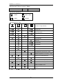
ACSON Service Guide Book
7
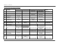
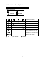
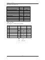
Handset
Type No.
Main Board (IC)
Model
W2
MC1.0 LWS2
APM01CB APM02D
Standard Optional
13 WM – GW Series
G18 SLM3 + AC5300 / Netware 3
14 CK – AW/AWH/CW Series
G18 SLM3 + AC5300 / Netware 3
15 CE – DW Series
G18 SLM3 + AC5300 / Netware 3
16 CE – EW Series
G18 SLM3 + AC5300 / Netware 3
17 CC – CW Series
SLM3 Netware 3
CW FCU
18 SB – BW Series N/A -
AC – C Series
AC 20 – 60C/CR
C. Panel -
AC 80 – 150C/CR
C. Panel -
5AC 20 – 25C/CR
C. Panel -
Mini Chiller
19
5AC 30 – 55C/CR
C. Panel -
20 5WMWS – GR
G18 SLM3 + AC5300 / Netware 3
21 5CKWS – AR/CR
G18 SLM3 + AC5300 / Netware 3
22 5CCWS – CR
SLM3 Netware 3
WH – B Series
WH 11 – 20B/BR
SLM15A -
WSHP
23
WH 25 – 70B/BR
APW04A -

ACSON Service Guide Book
8
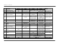
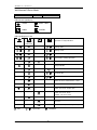
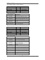
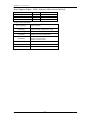
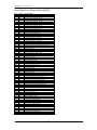
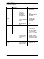
4.0 Controller Development History
Handset Model
Year Main Board
Wireless Wired Cooling Heating
Remarks
WM 10/15D WM 10/15DR Copper sensor
1996 Challenger 2.1 & 2.2 G3 -
WM 20/25C WM 20/25CR
1996 Challenger 2.2 G3 - WM 07/10E - Copper sensor
1997 Challenger 2.4 G3 & G6 -
WM 10/15D
WM 20/25C
WM10/15DR
WM 20/25CR
1998 Challenger 2.4 G3 & G6 - -
WM 07/10ER
WM 10/15FR
1998 Challenger 5
G3
G6
-
-
WM 07/10E
WM 10/15F
-
1999
Challenger C3A
Challenger C3B
Challenger C3B
G3 & G6 SLM2 (10 core wire)
CK-A
CE-C/D
CC-B/MSB/HSB
CK-AR
CE-CR/DR
CC-R/MSB-R/HSB-R
2000 Mini Chiller MCH01 - - AC (40-125)B AC (40-125)BR Cooling & Heatpump
2001 Chilled Water W1V2 G6 Netware 1
WM-FW / CE-DW / CC-CW / CK-AW / HSB-
BW
Convertible PCB
2001 Sequential Controller - Sequential Controller SB (150-500)B SB (150-500)BR Multiple compressor
Universal Board
D1.0 G6 - WM (10-25)F - Cooling only
U1.3 G6 - - WM (10-25)FR Heatpump only
2001
U1.4 G6 SLM3 (4 core wire) CE-D / CK-A / CC-C
CE-DR / CK-AR /
CC-CR
Cooling & Heatpump
2001 D2.0 G6 / G8 - WM (10-25)F - Cooling only
2001 Mini Chiller SZMC01 - -
AC/4AC (40-58)A,
AC/4AC75-125B
AC/4AC (40-58)AR,
AC/4AC75-125BR
Cooling & Heatpump
Inverter
VA1.9 (Indoor) G8 Turbo - - WMV10FR In set form only
2001
VB1.0 (Outdoor) SLV10BR
2002 Sequencer Controller - SQ-LCD SB (150-500)D SB (150-500)DR Multiple compressor
D2.0 G8 - WM30F - Cooling only
2002
U1.4 G8
SLM3 /
Netware 2 (optional)
CK (15/20/25/30)B
WM (10-25)FR,
WM30FR
CK (15/20/25/30)BR
Heatpump only
Cooling & heatpump

ACSON Service Guide Book
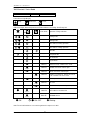
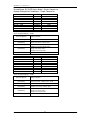
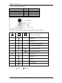
9
Handset Model
Year Main Board
Wireless Wired Cooling Heating
Remarks
2002 Chilled Water W1V3 G6
SLM3 /
Netware 2 (optional)
WM-FW / CE-DW / CC-CW / CK-AW / CK-BW
Valveless application
only
2002 Multi Split Indoor, MS10.0 G8 - - WMS (10-20)FR Auto random restart
2003 Mini Chiller MCH03A - SC302 AC/4AC(80-150)C AC/4AC (80-150)CR Cooling & heatpump
2003 Universal U1SB125 - SLM3 – single speed
SB (125/150)
B1/C1/D1
RT/4RT (60-120)A
SB (125/150)
BR1/CR1/DR1
RT/4RT (60-120)AR
Cooling & heatpump
RT/4RT (150-300)A
RT/4RT (150-
300)AR
SB 150B2-600B4 SB 150BR2-600BR4
2003 Sequential Controller, SQ - SQ-LCD
SB 125D2-500D4 SB125DR2-500DR2
Cooling & heatpump
2004 U1.4 G8 - CK (10-20)C CK (10-20)CR Cooling & heatpump
WM (07-15)G WM (07-15)GR
2004 L2.0 G12 -
WM (20-25)G WM (20-25)GR
Cooling & heatpump
MC01 - Chiller Panel AC (80-150)C AC (80-150)CR Cooling & heatpump
2004
MCH01 - Chiller Panel AC (20-60)C AC (20-60)CR Cooling & heatpump
G12 - CE (15-28)E CE (15-28)ER Cooling & heatpump
2005 L208A
- Netware 3 CC (75-100)D CC (75-100)DR Cooling & heatpump
U1.4 - SLM3 SB (75-100)ER
Universal U1SB125 - SLM3 – single speed SB (125-150)ER1
2005
Sequential Controller, SQ - SQ-LCD SB 125ER2-600ER4
Heatpump only
Inverter
VA2.0 G12 - 5WMX (10-25)GR In set form only
2005
5SLX (10-25)CR
2005 MC01 - Chiller Panel 5AC (030-055)CR Heatpump only
G8 & G12 SLM3 / Netware 3
CE-D / CK-A/B/C /
CC-C
CE-DR / CK-
AR/BR/CR / CC-CR 2006 L208A
- SLM3 SB (75-100)B/D SB (75-100)BR/ER
Cooling & Heatpump
2006 Sequential Controller, SQ - SQ-LCD RT (360-420)A RT (360-420)AR Cooling & Heatpump
2006 Chilled Water W2 G8 & G12 SML3 / Netware 3
WM-GW / CE-DW / CE-EW / CC-CW / CK-
AW/AWH/CW / SB-BW
2008 L2GSN G18 - (5)WM-J/JR Cooling & Heatpump
2009 W_2_03A G18 - 5WMY-J/JR Cooling & Heatpump

ASCON Service Guide Book
10
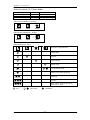
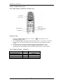
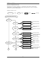
5.0 Handset Operating Guide
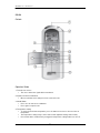
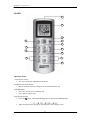
5.1 G6
Outlook
Operation Guide
1. “ON/OFF” Switch
•
Press to start the air conditioner unit.
•
Press again to stop the unit.
2. Temperature Setting
•
Set the desire room temperature.
•
Press button to increase or decrease the set temperature. Setting range are between 16°C to
30°C setting (60°F to 80°F) (Optional setting from 20°C to 30°C).
•
Press
▲
or
▼
button simultaneously will toggle the temperature setting between °C and °F.
3. Automatic Air Swing
•
Press the button to activate the automatic air swing function. The swing angle ranging from
horizontal to 25° to bottom.
4. “SLEEP” MODE
•
Press the button to activate sleep mode. This mode can only be activated while in cooling or
heating mode operation. If it is activated in “COOL” mode, the set temperature will be
increase 0.5°C after 30 minutes, 1°C after 1 hour and 2°C after 2 hours. Whereas in “HEAT”
mode, the set temperature will decrease by 1°C after 30mins, 2°C after 1 hour and 3°C after 2
hours.
•
This function is available under COOL, HEAT & AUTO mode.

ASCON Service Guide Book
11
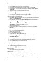
5. Timer Setting
Press set button to activate the timer setting (from 1 hour to 15 hour) of the air conditioning
unit. It will be in “On” or “Off” condition after the set time depending to the current condition
(either from “On” to Off” or vise versa)
To cancel the timer setting, press the button continuously until the timer display goes off.
6. Operation Modes
•
Press the “mode” button for select the type of operating mode.
•
Cooling only unit:
Cool
→
Dry
→
Fan.
•
Heatpump unit:
Auto
→
Cool
→
Dry
→
Fan
→
Heat
7. Fan Speed and Ventilation Mode Selection
•
Press the button until the desired fan speed is achieved.
8. Signal Transmission Indication
•
Blink to confirm the last setting has been send to the unit.

ASCON Service Guide Book
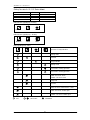
12
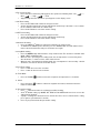
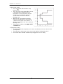
5.2 G8
Outlook
Operation Guide
1. Transmission Source
•
The source where the signal will be transmitted.
2. Signal Transmission Indication
•
Blink to confirm the last setting has been send to the unit.
3. On/Off Button
•
Press once to start the air conditioner.
•
Press again to stop the unit.
4. Temperature Setting
•
To set the desired room temperature, press the button to increase or decrease the set
temperature.
•
The temperature setting range is from 16°C to 30°C (Optional setting 18°C to 30°C).
•
Press both buttons simultaneously to toggle the temperature setting between °C and °F.

ASCON Service Guide Book
13
5. Operation Mode
•
Press the MODE button to select the type of operating mode.
•
For cooling only unit, the available modes are: COOL, DRY & FAN.
•
For heat pump unit, the available modes are: AUTO, COOL, DRY, FAN & HEAT.
6. Fan Speed Selection
•
Press the button until the desired fan speed is achieved.
7. On Timer Setting
•
Press the SET button will activate the on timer function.
•
Set the desired on time by pressing the SET button continuously. If the timer is set to 7.30am,
the air conditioner will turn on at 7.30 sharp.
•
Press the CLR button to cancel the on timer setting.
8. Off Timer Setting
•
Press the SET button will activate the off timer function.
•
Set the desired off time by pressing the SET button continuously.
•
Press the CLR button to cancel the off timer setting.
9. Automatic Air Swing (Optional)
•
Press the SWING button to activate the automatic air swing function.
•
To distribute the air to a specific direction, press the SWING button and wait until the louver
move to the desired direction and press the button once again.
10. Sleep Mode Setting
•
Press the button to activate sleep mode. This function is available under COOL, HEAT &
AUTO mode.
•
When it is activated in COOL mode, the set temperature will be increased 0.5°C after 30mins,
1°C after 1 hour and 2°C after 2 hours.
•
When it is activated in HEAT mode, the set temperature will be decreased 1°C after 30mins,
2°C after 1 hour and 3°C after 2 hours.
11. Clock Time Setting
•
Press button + or - to increase or decrease the clock time.
12. Turbo Function (Optional – Only Applicable To Inverter Unit)
•
Press button for fast cooling or heating operation.
•
The temperature will be increased internally if it is in the HEAT mode, decreased if in COOL
or DRY mode. Fan speed will be increased if it is not at maximum speed.
•
The temperature & fan speed will resume to user setting if the button is pressed again or after
20mins.
•
Available under HEAT, COOL & DRY modes only.

ASCON Service Guide Book
14
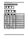
5.3 G12
Outlook
Operation Guide
1. “ON/OFF” Button
•
Press once to start the air conditioner unit.
•
Press again to stop the unit.
2. Temperature Setting
•
To set the desired room temperature, press
▲
the button to increase or
▼
button to decrease
then set temperature.
•
The temperature setting range is from 16°C to 30°C.
•
Press both buttons simultaneously to toggle and from
▲
°C to
▼
°F setting.
3. Operation Mode
•
Press the MODE button to select the type of operating mode.
•
For cooling only unit, the available modes are: COOL ( ), DRY ( ) and FAN ( ).
•
For heat pump unit, the available modes are: AUTO, COOL ( ), DRY ( ), FAN ( ) and
HEAT ( ).

ASCON Service Guide Book
15
4. Fan speed selection
•
Press the button continuously will toggle the fan speed in the following order: Low ( ) –––:
Med ( ) –––: High ( ) –––: Auto
•
Stop pressing when the desired fan speed appears on the display screen.
5. ON Timer Setting
•
Press the SET button will activate the on timer function.
•
Set the desired on time by pressing the SET button continuously. If the timer is set to 7.30am,
the air conditioner will turn on at 7.30am sharp.
•
Press the CLR button to cancel the on timer setting.
6. OFF Timer Setting
•
Press the SET button will activate the off timer function.
•
Set the desired off time by pressing the SET button continuously.
•
Press the CLR button to cancel the off timer setting.
7. Automatic Air Swing
•
Press the SWING ( ) button to activate the automatic air swing function.
•
To distribute the air to a specific direction, press the SWING button and wait until the louver
move to the desired direction and press the button once again.
8. Sleep Mode Setting
•
Press the SLEEP button will activate the sleep mode function. This function is available under
COOL, HEAT and AUTO mode.
•
When the unit is operating under cooling mode, the set temperature is increased by 0.5°C
after 30 minutes, 1°C after an hour, and 2°C after 2 hours.
•
When the unit is operating under heating mode, the set temperature is decreased by 1°C after
30 minutes, 2°C after an hour and 3°C after 2 hours.
9. Clock Time Setting
•
Press + button to increase the clock time.
•
Press – button to decrease the clock time.
10. Turbo Mode
•
Press the TURBO ( ) button to achieve the required set temperature in a short time.
11. Ionizer
•
Press the Ionizer ( ) button to activate the negative Ion function, which will refresh the
indoor air effectively.
12. Personalize Setting
•
Press button and hold for 3s to initiate personalized setting
•
Set the individual setting e.g. MODE, SET TEMP or FAN SPEED and leave for 4s to save the
setting into the program.
•
2 groups of settings are allowed to store in the handset. Press once to activate the P1 setting,
press again to cycle between P1 and P2.
•
Press any key to deactivate the personalize setting.

ASCON Service Guide Book
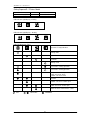
16
5.3 G18
Outlook
Operation Guide
1. Transmission Source
•
The source where the signal will be transmitted.
2. Signal Transmission Indication
•
Blink to confirm that the last setting has been transmitted to the unit.
3. Temperature Setting
•
To set the desired room temperature, press the
▲
or
▼
button to increase or decrease
the set temperature.
•
Temperature setting range is from 16°C to 30°C (optional setting 20°C to 30°C).
4. Personalize Setting
•
Press and hold for 3s, then will blink. Press again to cycle between and .
•
Set the desire setting, then leave the handset for 4s without pressing any key and it will save
the setting into the program.
•
Press once to activate the P1 setting, press again to cycle between P1 and P2.
•
Press any key to deactivate the personalize setting.

ASCON Service Guide Book
17
5. Automatic Air Swing (optional)
•
Press the SWING button to activate the automatic air swing function.
•
To distribute the air to a specific direction, press the SWING button and wait until the
louver move to the desired direction and press the button once again.
6a. Silent Function (For WM – J Series only)
•
Press for quiet operation.
•
Fan speed turn to minimum speed.
•
Press again to deactivate the function.
6b. Ionizer Function (For WM - G series only)
•
Press button to activate the negative ion function, which will refresh the indoor air
effectively.
7. Sleep Mode Setting
•
Press the SLEEP button will activate the sleep mode function. This function is available under
COOL, HEAT and AUTO mode.
•
When the unit is operating under cooling mode, the set temperature is increased by 0.5°C
after 30 minutes, 1°C after an hour, and 2°C after 2 hours.
•
When the unit is operating under heating mode, the set temperature is decreased by 1°C after
30 minutes, 2°C after an hour, and 3°C after 2 hours.
8. Operating Mode
•
Press the MODE button to select the type of operating mode.
•
For cooling only unit, the available modes are: COOL ( ), DRY ( ) and FAN ( ).
9. Fan Speed Selection
•
Press the button continuously will toggle the fan speed in the following order:
Low Med High Auto
•
Stop pressing when the desired fan speed appears on the display screen.
10. “ON/OFF” Button
•
Press one to start the air conditioner unit.
•
Press again to stop the unit.
11. Timer Cancel
•
Press the TIMER CANCEL button to cancel the on timer setting.
12. OFF Timer Setting
•
Press the OFF TIMER button will activate the off timer function.
•
Set the desired off time by pressing the OFF TIMER button continuously.
13. ON Timer Setting
•
Press the ON TIMER button will activate the on timer function.
•
Set the desired on time by pressing the ON TIMER button continuously. If the timer is set to
7.30am, the air conditioner will turn on at 7.30am sharp.
14. Turbo Function
•
Press for fast cooling.
•
Fan speed turn to maximum speed.
•
Press again to deactivate the function.
15. Clock Time Setting
•
Press and hold to set the clock time.

ASCON Service Guide Book
18
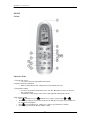
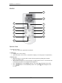
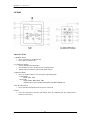
5.4 GS02
Operation Guide
1. Transmission Source
•
The source where the signal will be transmitted.
2. Signal transmission indication
•
Blink to confirm that the last setting has been transmitted to the unit.
3. ON/OFF Button
•
Press once to start the air conditioner unit.
•
Press again to stop the unit.
4. Fan Speed selection
•
Press the button continuously will toggle the fan speed in the following order:
•
Stop pressing when the desired fan speed appears on the display screen.
1
2
3
4
5
6
7
8
9
10
11
12
13

ASCON Service Guide Book
19
5. Operation mode
•
Press the MODE button to select the type of operating mode.
•
For cooling only unit, the available modes are: COOL , DRY and FAN .
•
For heat pump unit, the available modes are: AUTO , COOL , DRY , FAN
and HEAT .
•
The AUTO mode is unavailable for chilled water system.
•
6. Automatic air swing
•
Press the SWING button to activate the automatic air swing function.
•
To distribute the air to a specific direction, press the SWING button and wait until the
louver move to the desired direction and press the button once again.
Swing mode selection method (for CK-E model)
•
Press SWING button for 4 seconds to enter field setting mode. While in field setting mode,
it will only show SWING MODE .
•
Press temperature and button to select SWING MODE rotation from Swing Mode 1 to
Swing Mode 3.
•
There are 3 different SWING MODE, which are:
Swing mode 1 Swing mode 2 Swing mode 3
SWING MODE will not activate unless SWING is activated.
Swing is indicated by the logo:
•
If no mode changes within 4 seconds, unit will operate according to the selected SWING
MODE .
7. Turbo function (model dependent)
•
Press for fast cooling or heating operation.
•
Fan speed turn to maximum speed.
•
Press again to deactivate the function.
•
Available under HEAT, COOL and DRY modes only.
•
Any change of fan speed will deactivate this function.
•
The Turbo function is unavailable for chilled water system and remote control with
SWING MODE function.
•
8. OFF timer setting
•
Press the OFF TIMER CANCEL button will activate the off timer function.
•
Set the desired off time by pressing the OFF TIMER CANCEL button continuously.
•
Press the CANCEL button to cancel the off timer setting.
9. Quiet function (model dependant)
•
Press for quiet operation.
•
Fan speed turn to minimum speed.
•
Press again to deactivate the function.
•
Any change of fan speed will deactivate this function.
•
The Silent function is unavailable for chiller water system.
•
10. Clock time setting
•
Press and hold button to set the clock time.
11. ON timer setting
•
Press the ON TIMER CANCEL button will activate the on timer function.
•
Set the desired on time by pressing the ON TIMER CANCEL button continuously. If the timer
is set to 7.30am, the air conditioner will turn on at 7.30am sharp.
•
Press the CANCEL button to cancel the on timer setting.
Page is loading ...
Page is loading ...
Page is loading ...
Page is loading ...
Page is loading ...
Page is loading ...
Page is loading ...
Page is loading ...
Page is loading ...
Page is loading ...
Page is loading ...
Page is loading ...
Page is loading ...
Page is loading ...
Page is loading ...
Page is loading ...
Page is loading ...
Page is loading ...
Page is loading ...
Page is loading ...
Page is loading ...
Page is loading ...
Page is loading ...
Page is loading ...
Page is loading ...
Page is loading ...
Page is loading ...
Page is loading ...
Page is loading ...
Page is loading ...
Page is loading ...
Page is loading ...
Page is loading ...
Page is loading ...
Page is loading ...
Page is loading ...
Page is loading ...
Page is loading ...
Page is loading ...
Page is loading ...
Page is loading ...
Page is loading ...
Page is loading ...
Page is loading ...
Page is loading ...
Page is loading ...
Page is loading ...
Page is loading ...
Page is loading ...
Page is loading ...
Page is loading ...
Page is loading ...
Page is loading ...
Page is loading ...
Page is loading ...
Page is loading ...
Page is loading ...
Page is loading ...
Page is loading ...
Page is loading ...
Page is loading ...
Page is loading ...
Page is loading ...
Page is loading ...
Page is loading ...
Page is loading ...
Page is loading ...
Page is loading ...
Page is loading ...
Page is loading ...
-
 1
1
-
 2
2
-
 3
3
-
 4
4
-
 5
5
-
 6
6
-
 7
7
-
 8
8
-
 9
9
-
 10
10
-
 11
11
-
 12
12
-
 13
13
-
 14
14
-
 15
15
-
 16
16
-
 17
17
-
 18
18
-
 19
19
-
 20
20
-
 21
21
-
 22
22
-
 23
23
-
 24
24
-
 25
25
-
 26
26
-
 27
27
-
 28
28
-
 29
29
-
 30
30
-
 31
31
-
 32
32
-
 33
33
-
 34
34
-
 35
35
-
 36
36
-
 37
37
-
 38
38
-
 39
39
-
 40
40
-
 41
41
-
 42
42
-
 43
43
-
 44
44
-
 45
45
-
 46
46
-
 47
47
-
 48
48
-
 49
49
-
 50
50
-
 51
51
-
 52
52
-
 53
53
-
 54
54
-
 55
55
-
 56
56
-
 57
57
-
 58
58
-
 59
59
-
 60
60
-
 61
61
-
 62
62
-
 63
63
-
 64
64
-
 65
65
-
 66
66
-
 67
67
-
 68
68
-
 69
69
-
 70
70
-
 71
71
-
 72
72
-
 73
73
-
 74
74
-
 75
75
-
 76
76
-
 77
77
-
 78
78
-
 79
79
-
 80
80
-
 81
81
-
 82
82
-
 83
83
-
 84
84
-
 85
85
-
 86
86
-
 87
87
-
 88
88
-
 89
89
-
 90
90


Acson A4LC Troubleshooting guide
- Category
- Remote controls
- Type
- Troubleshooting guide
Ask a question and I''ll find the answer in the document
Finding information in a document is now easier with AI
Related papers
-
Acson A5WMY10KR Operating instructions
-
-
Acson A5CK30AR User manual
-
-
-
-
-
Acson A5LC25CR Installation guide
-
Acson A5MSY20BR User manual
-
Other documents
-
Fujitsu ARY25ALA Operating instructions
-
Frigidaire FRP12ETT2R Product information
-
Sanyo SAP-KRV18AP User manual
-
Airwell RC3-LCD Programming And Operations Manual
-
-
-
-
Halcyon UTP-PU03B Troubleshooting Manual
-
McQuay MMC Troubleshooting guide
-
Daikin RXN35MV1 User manual