American Water Heater 520 Owner's manual
- Category
- Water heaters & boilers
- Type
- Owner's manual
This manual is also suitable for

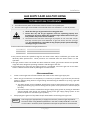
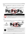
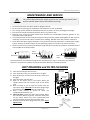
‐Do not store or use gasoline or other
flammablevaporsandliquidsinthevicinityof
thisoranyotherappliance.
‐WHATTODOIFYOUSMELLGAS
Donottrytolightanyappliance.
Do not touch any electric switch, do not
useanyphonein
yourbuilding.
Immediatelycallyourgassupplierfroma
neighbor's phone. Follow the gas
supplier'sinstructions.
Ifyoucannotreachyourgassupplier,call
thefiredepartment.
‐Installation and service must be performed
byaqualifiedinstaller,serviceagencyorthe
gassupplier.
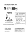
520(T‐H2)and320(T‐H2S)
InstallationManualandOwner’sGuide
FEATURING
ENDLESSHOTWATER
ONDEMANDUSAGE
COMPACT,SPACESAVING
ENERGYCONSERVATION
COMPUTERIZEDSAFETY
NOPILOTLIGHT
EASY‐LINKSYSTEM
Ifyouhaveanyquestions,please
callorwriteto:
500TennesseeWaltzParkway
AshlandCity,TN37015
TollFree:1‐877‐737‐2840
ANSI Z21.10.3andCSA4.3
GasTanklessWaterHeater
DirectVentIndoormodels(520Indoor(T‐H2‐DV),
320Indoor(T‐H2S‐DV))
Outdoormodels(520Outdoor(T‐H2‐OS),
320Outdoor(T‐H2S‐OS))
Suitableforpotablewaterheatingandspace‐heating
*
*Pleaserefertolocalcodesforspace‐heatingcompliance.
Iftheinformationinthese
instructionsisnotfollowed
exactly,afireorexplosion
mayresultcausing
propertydamage,personalinjuryordeath.
WARNING
520(T‐H2)models
only

Contents
2│Page
NOTE
Checktheratingplatetoensurethisproductmatchesyour
specifications.
In accordance with ANZI Z21.10.3, CO emission does not
exceed400PPMfornormalinput.
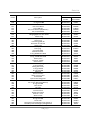
CONTENTS
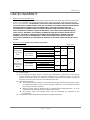
SPECIFICATIONS
520 (T‐H2) and 320(T‐H2S)models
GasInput
520
(T‐H2)
models
Natural
Min:13,000Btu/h
Max:199,000Btu/h
Propane
320
(T‐H2S)
models
Natural
Min:13,000Btu/h
Max:180,000Btu/h
Propane
GasConnection ¾”NPT
WaterConnections ¾”NPT
CondensateDrainPort
Connection
½”NPT
WaterPressure* 15‐150psi
NaturalGas
Inlet Pressure
Min.5.0”WC
Max.10.5”WC
Propane
Inlet Pressure
Min.8.0”WC
Max.14.0”WC
ManifoldPressure**
520Direct
VentIndoor
(T‐H2‐DV)
Natural:3.2”WC
Propane:5.5”WC
520Outdoor
(T‐H2‐OS)
Natural:2.7”WC
Propane:4.6”WC
320Direct
VentIndoor
(T‐H2S‐DV)
Natural:2.5”WC
Propane:4.3”WC
320Outdoor
(T‐H2S‐OS)
Natural:1.9”WC
Propane:3.6”WC
Weight
73lbs.
(DirectVentIndoormodels)
71lbs.(Outdoormodels)
Dimensions H25.6”xW18.5”xD12.4”
Ignition ElectricIgnition
Electric
Supply 120VAC/60Hz
Consumption
Operationofthe
DirectVent
Indoormodels
152W
(1.27A)
Operationofthe
Outdoormodels
102W
(0.85A)
Standby
8.2W
(0.07A)
Freeze‐
Protection
207W
(1.73A)
SPECIFICATIONS………………………………...
INTRODUCTION……………………………….…
SAFETYGUIDELINES…………….……………..
INSTALLATION………………………………..….
General………………………………………..…
IncludedAccessories…………………..…
Optionalitems…………………………..…..
WarningforInstallations………..….....
High‐altitudeInstallations………………
Installationforoutdoormodels……..
Installationfordirectventindoor
models……………………………………………
VentingInstructions……………………....
GasSupply/GasPipeSizing………...…
WaterConnections……………..……….…
PressureReliefValve………………………
Condensatedrain…………………………..
ElectricalConnections…………….........
RemoteControllerConnection…….…
PumpControlConnections………..……
PumpControlMode…………………….…
Easy‐LinkSystem…………………………....
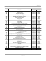
APPLICATIONS...…………………………………
SpaceHeating……….………….……………
INITIALOPERATION..…………………….……
OPERATINGSAFETY……………………………
NORMALOPERATION…………………………
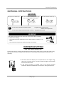
General………..……….………….……………
Temperaturesettings.…….…..…………
Flow……………………………………………….
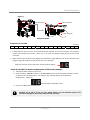
FreezeProtectionSystem…….…………
MaintenanceandService………………
UnitDrainingandFilterCleaning……
TROUBLESHOOTING……..……………………
General………..……….………….……………
Errorcodes.…………………….…..…………
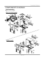
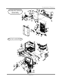
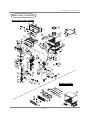
COMPONENTSDIAGRAM………………..…
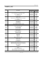
PARTSLIST………………….………………………
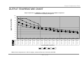
OUTPUTTEMPERATURECHART……...…
LIMITEDWARRANTY…………………….……
2
3
4
5
6
6
7
8
9
9
10
10
17
19
20
20
22
23
24
25
27
31
31
33
34
36
36
36
38
38
39
39
40
40
42
44
47
50
51
Themanufacturerreservestherighttodiscontinue,orchangeat
anytime,specificationsordesignswithoutnoticeandwithout
incurringobligations.
InstallationManual
Owner’sGuide
*40psioraboveisrecommendedformaximumflow.
**TheManifoldPressureisthefactorysettingandgenerally
shouldnotneedadjustment.

Introduction
3│Page
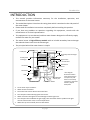
INTRODUCTION
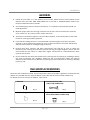
*Thisdiagram
illustratestankless
waterheaterdesign
conceptsonlyand
doesnotaccurately
representtothewater
heater’sphysical
description.
This manual provides information necessary for the installation, operation, and
maintenanceofthewaterheater.
Themodeldescriptionislistedontheratingplatewhichisattachedtothesidepanelof
thewaterheater.
Pleasereadallinstallationinstructionscompletelybeforeinstallingthisproduct.
If you have any problems or questions regarding this equipment, consult with the
manufactureroritslocalrepresentative.
Thisequipmentisanon‐demand,tanklesswaterheatersdesignedtoefficientlysupply
endlesshotwaterforyourneeds.
Theprinciplebehindthewaterheaterissimple:
1. Ahotwatertapisturnedon.
2. Waterenterstheheater.
3. Thewaterflowsensordetectsthewaterflow.
4. Thecomputerautomaticallyignitestheburner.
5. Watercirculatesthroughtheheatexchangerandthengetshot.
6. Thecomputerwillmodulate the
gassupplyvalveandwaterflowtoproducetheright
amountofhotwateratthecorrecttemperature.
7. Whenthetapisturnedoff,theunitshutsdown.
Thewaterheaterishigh efficiencymodelswithanin‐buildsecondaryheatexchanger
thatabsorbslatentheatfromtheexhaustgas.
Burner
Condensate
drainport
Secondaryheatexchanger
Thermistor
Thermistor
GasValve
Flowsensor
Watercontrolvalve
B
yp
assvalve
Intake
p
ort
Exhaust
Fanmotor
Primaryheat
exchanger
Thermistor
PCB
HotWaterOutlet
ColdWaterOutlet
Gas

SafetyGuidelines
4│Page
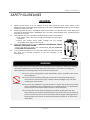
Watertemperaturesover125°F(52°C)cancausesevereburnsinstantlyordeathfromscalding.
Thewatertemperatureissetat120°F(49°C)fromthefactorytominimizeanyscaldingrisk.
Beforebathingorshoweringalwayscheckthewatertemperature.
Donotstoreorusegasolineorotherflammables,vapors,orliquidsinthevicinity
ofthisappliance.
Donotreversethewaterand/orgasconnectionsasthiswilldamagethegas
valvesandcancausesevereinjuryordeath.Followthediagramonp.19when
installingyourwaterheater:
Donotusethisapplianceifanyparthasbeenincontactwithorbeenimmersedin
water.Immediatelycallalicensedplumber,alicensedgasfitter,oraprofessional
servicetechniciantoinspectand/orservicetheunitifnecessary.
Donotdisconnecttheelectricalsupplyiftheambienttemperaturewilldrop
belowfreezing.TheFreezePreventionSystemonlyworksiftheunithaselectrical
power.Thewarrantywillnotbecoverediftheheatexchangerisdamageddueto
freezing.RefertothesectionontheFreezePreventionSystemon
p.38formore
information.
SAFETYGUIDELINES
GENERAL
1. Follow all local codes, or in the absence of local codes, follow the most recent edition of the
NationalFuelGasCode:ANSIZ223.1/NFPA54intheUSAorCAN/CSAB149.1NaturalGas,Propane
InstallationCodeinCanada.
2. Properlygroundtheunitinaccordance withalllocal codes or in
theabsenceoflocalcodes,with
theNationalElectrical Codes:ANSI/NFPA70 in theUSAorCSAstandard C22.1 Canada Electrical
CodePart1inCanada.
3. Carefullyplanwhereyouintendtoinstallthe waterheater.Pleaseensure:
Your water heater will have enough combustible air and proper
ventilation.
Locate your heater where water leakage will not damage
surroundingareas(pleaserefertop.5).
4. ChecktheratingplateforthecorrectGASTYPE,GASPRESSURE,WATER
PRESSUREandELECTRICRATING.
*If this unit does not match your requirements, do not install and
consultwiththemanufacturer.
5. Ifanyproblemshouldoccur,turnoffallhotwatertapsandturnoffthe
gas. Then call a trained technician or the Gas Company or the
manufacturer.
Prohibited
WARNING
RATINGPLATE

Installation
5│Page
Installation and service must be performed by a qualified installer (for
example, a licensed plumber or gas fitter), otherwise the warranty will be
void.
Theinstaller(licensedprofessional)isresponsibleforthecorrectinstallation
of the water heater and for compliance with all national, state/provincial,
andlocalcodes.
Thewarrantywillnotcoverdamagecausedbywaterquality.
Onlypotablewaterorpotablewater/glycolmixturescanbeusedwiththis
water heater.Do not introduce pool or spa water, or any chemically
treatedwaterintothewaterheater.
Water hardness levels must not exceed 7 grains per gallon (120 ppm) for
single family domestic applications or more than 4 grains per gallon (70
ppm) for all other types of applications.Water hardness leads to scale
formation and may affect/damage the water heater.Hard water scaling
mustbeavoidedor
controlledbyproperwatertreatment.
WaterpHlevelsmustbebetween6.5and8.5
Wellwatermustbetreated.
Although th is water heater is designed to operate with minimal sound, the
manufacturerdoesnotrecommendinstallingtheunitonawalladjacenttoa
bedroom,oraroomthatisintendedforquietstudyormeditation,etc.
Locateyourheatercloseto adrainwherewaterleakagewillnotdodamageto
surrounding areas.As with any water heating appliance, th e potential for
leakage at some time in the life of the product does exist.The manufacturer
will not be responsible for any water damage that may occur.
If you install a
drainpanundertheunit,ensurethatitwillnotrestrictthecombustio nairflow.
The water heater is high efficiency products that create condensation. A
condensation drain tube must be installed with these models to discharge
condensateintoadrainoutlet.Formoreinformation,refertop.20.
The manufacturer does not recommend installing the Direct Vent Indoor
modelsin an atticduetosafetyissues.IfyouinstallyourDirectVentIndoor
modelsinanattic:
Make sure your unit will have enough combustion air and proper
ventilation.
Keeptheareaaround you’rethewaterheaterclean.Whendustcollectson
theflamesensor,thewaterheaterwillshutdownonerrors.
Locateunitforeasyaccessforserviceandmaintenance.
A drain pan, or other means of protection against water damage, is
requiredtobeinstalledunderthewaterheaterincaseofleaks.
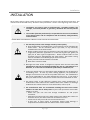
INSTALLATION
Allgaswaterheatersrequirecarefulandcorrectin stallationtoensuresafeandefficientoperation.This
manualmustbefollowedexactly.Readthe“SafetyGuidelines”section atthebeginningofthismanual.
WARNING
WARNING
CAUTION
PLEASEREADTHISMANUALCAREFULLYANDFOLLOWALLDIRECTIONS.

Installation
6│Page
GENERAL
1. Follow all local codes, or in the absence of local codes, follow the most recent edition of the
National Fuel Gas Code: ANSI Z223.1/NFPA 54 in the USA or CAN/CSA B149.1 Natural Gas,
PropaneInstallationCodeinCanada.
2. Themanifoldgaspre s sureispresetatthefactory.It
iscomputercontrolledandshouldnot
needadjustment.
3. Maintainproperspaceforservicing.Installtheunitsothatitcanbeconnectedorremoved
easily.Refertop.8,p.9andp.10forproperclearances.
4. Theelectricalconnectionrequiresameansofdisconnection,toterminatepowertothewater
heaterforservicingandsafetypurposes.
5. Ifyouwillbein stallingtheunitinacontaminatedareawithahighlevelofdust,sand,flour,
aerosolsorothercontaminants/chemicals,theycanbecomeairborneandenterandbuildup
withinthefanandburnercausingdamagetotheunit.
6. Particles from flour, aerosols, and other contaminants may clog the air vent or reduce the
functions of the rotatingfanandcauseimproperburningofthegas.Regularlyensurethatthe
area around the unit is dust‐ or debris‐free; regular maintenance is recommended for these
typesofenvironment.
7. Donotinstalltheunitwheretheexhaustventispointingintoanyopeninginabuildingorwhere
the noise may disturb your neighbors. Make sure the vent termination meets the required
distancebylocalcodefromany doorwayoropeningtopreventexhaustfromenteringabuilding
(refer
top.15).
INCLUDEDACCESSORIES
Checkthattheinstallationmanual,thecommunicationcable,theproductregistrationcardandthePVC
adaptorareincludedwiththeunit(theadapto rcomeswiththeDirectVentIndoormodelsonly.
Fordetailsonhowtoconnecttheadaptor,refertoP.14.
1.Manual
2.Communicationcable
520(T‐H2)modelsonly
3.ProductRegistrationCard
4.PVCadaptor
DirectVentIndoormodelsonly
Qty:1
Qty:1
Q
t
y
:1
Qty:1

Installation
7│Page
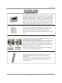
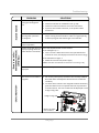
OPTIONALITEMS
1.TemperatureRemoteController:9007603005(TM‐RE30)
The Temperature Remote Controller has two functions. It allows
the output temperature from the water heater to be adjusted
within the range of 100 °F to 185 °F, and it also works as a
diagnostictoolthatwillgiveaconciseerrorcodewheneverthere
is a problem with the unit. The temperature options are 100°F,
105°F, 110°F, 115°F, 120°F, 125°F, 130°F, 135°F, 140°F, 145°F,
150°F,155°F,160°F,165°F,170°F,175°F,180°Fand185°F.Seethe
troubleshootingsectionforinformationonpossibleerrorcodes.
2.Pipecover:9007606005(TH‐PC02)
ThePipecoverprotectstheplumbingpipestothewaterheater
fromunexpectedadjustments.Thispipecoverisfixedtothe
bottomofthewaterheater,whichhidestheplumbingand
improvesthevisualaspectsofthewholeinstallationforthewater
heater.
3.WallthimblewithTermination:9007608005(TK‐KPWL4)and9007609005(TK‐KPWH4)
Theseterminationsareusedwhenventingoutthroughthewalland
arecompatiblewiththeT‐Ventpipesystem.
Theseterminationsarespecialstainlesssteelventsforgasappliances
andareULlistedasCategoryII,IIIandIV.Therearetwotypesof
terminations:theLouverterminationandtheHood
termination.For
differentwallthicknesses,therearetworangesof lengthsavailable
(refer totheventingbrochurefordetails).
Installthesevent terminationsinaccordancewiththeirinstallation
instructionsandanyapplicablelocalcodes.
4.Neutralizerkit:9007607005(TH‐NT01)
TheNeutralizerassemblyneutralizesthecondensate(acidic
water)thatformsinthesecondaryheatexchangerofthe
waterheater.
Itconnectstothecondensatedrainportofthewaterheaterby
usingconnectorsincludedwiththeneutralizerkit.Refertop.
21forthe
details.
Louver
Termination
9007608005
(TK‐KPWL4)
Hood
Termination
9007609005
(TK‐KPWH4)

Installation
8│Page
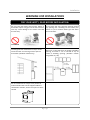
WARNINGFORINSTALLATIONS
FORYOURSAFETY,READBEFOREINSTALLATION:
Do not install the heater where water, debris or
flammablevaporsmaygetintotheflueterminal.
This may cause damage to the heater and void
thewarranty.
Do not have the vent terminal pointing toward
any opening into a building. Do not locate your
heater in a pit or
location where gas and water
canaccumulate.
Donotinstallthiswaterheaterunderan
overhanglessthan3feetfromitstoporeaves.
Theareaunderanoverhangmustbeopento
threesides.(Outdoormodelsonly)
Do not install the water heater vent terminator
within1ft.intheUSAofanyairintake
orbuilding
opening, and with in 3 ft. in Canada of any air
intake or building opening. (Outdoor models
only)(Refertop.15)
Donotinstallnexttoadryeroranysourceof
airbornedebristhatcanbetrappedinsidethe
combustionchamber,unlessthesystemisdirect
vented.
Prohibited
Prohibited
FORYOURSAFETY,READBEFOREINSTALLATION:

Installation
9│Page
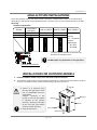
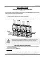
Thedarksquaresindicatethedirectionthe
dipswitchesshouldbesetto.
Leftbankofdipswitches
Leftbankofdipswitches
There is a 3” clearance from
the left and right sides of the
unit to combustible and non‐
combustible
surfaces.However, if any
portion or area of the surface
is exposed to the exhaust
fumes(i.e.directlytothesides
of the vent cap), that surface
mustbeatleast24”
away.
Keeptheclearances.
2,500to4,000ft
4,000 to5,000 ft
Altitude
HIGH‐ALTITUDEINSTALLATIONS
Checktheelevationwhereyourwaterheaterisinstalled.Setdipswitchesshowninthetablebelow
dependingonthealtitude.Thesedipswitches(No.5andNo.6)areonthecomputerboardontheleft
bankonly.
0to2,500ft
(DEFAULT)
Over5,000ft
SwitchNo.5 OFF
ON
OFF
Consult
our Technical
Services
Department
at1‐877‐
737‐2840
SwitchNo.6
OFF OFF ON
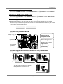
INSTALLATIONFOROUTDOORMODELS
1. InstalltheOutdoormodelonlyinareaswithmild,temperateclimates.
2. TheOutdoormodelshallbewall‐mountedormountedonastand.Locate theOutdoormodelin
anopen,unroofedareaandmaintainthefollowingminimumclearances:
DONOTadjustanydipswitchesontherightbank.
1
2
3
4
5
6
7
8
N
O
9
1
0
N
O
1
2
3
4
5
6
7
8
9
1
0
N
O
1
2
3
4
5
6
7
8
9
1
0
Side3”
Top36”
Side3”
Front24”
Bottom12”
Back0.5”

Installation
10│Page
Improperventingofthisappliancecanresultinexcessivelevelsofcarbonmonoxide
whichcanresultinseverepersonalinjuryordeath.
Wheninstallingtheventsystem,allapplicablenationalandlocalcodesmustbe
followed.Ifyouinstallthimbles,firestopsorotherprotectivedevicesandthey
penetrateanycombustibleornoncombustibleconstruction,besuretofollowall
applicablenationalandlocalcodes.
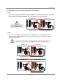
INSTALLATIONFORDIRECTVENTINDOORMODELS
TheDirectVent Indoor modelsareequippedwithathermistorandhi‐limitswitchfor the exhaustgas,
detectingexcesstemperatureswithintheflueandenablingtheunittosafelystopoperationsifneeded.
These components are always monitoring exhaust gas conditions in order to prevent heat damage to
PVC(Plastic)ventingifPVCisused.
If the exhaust gas temperature exceeds 140°F, these components will enable the unit to safely stop
operations.(For the Outdoor model, these components are not available since there’s no exhaust
ventingrequ ired.)
TheDirectVentIndoormodelrequiresa
4” make‐up intake air supply pipe. The
intakepipemustbesealedairtight.
AirsupplypipecanbemadeofABS,PVC,
galvanized steel, corrugated stainless
steel,orCategorylll/IVstainlesssteel.
Sidewallventingisrecommendedforthe
Direct Vent Ind oor model. Vertical
venting(rooftermination)isacceptable.
The manufacturer recommends
running the exhaust vent and the
intakepipeasparallelasp ossible.
ThePVCadaptorisusedtomake the
connection between the Direct Vent
Indoor model vent collar and PVC
ventpipeeasierand
formaintenance
purposes.
VENTINGINSTRUCTIONS
‐General‐
TheDirectVentIndoormodelsmustbeventedinaccordancewiththesection“VentingofEquipment"
of the latest edition of the National Fuel Gas Code: ANSI Z223.1/NFPA 54 in the United States and/or
Section 7 of the CAN/CSA B149.1 Natural Gas and Propane Installation Code in
Canada, as well as
applicablelocalbuildingcodes.
TheuseofventingmaterialsapprovedforCategoryIII/IVappliance sisrecommendedwheneverpossible.
However,theDirectVentIndoormodelsmayalsobeventedwithplasticpipematerialssuchasPVC.For
details,pleasereferto theExhaustVent(PVC Vent)sectiononp.11.VentinstallationsinCanadawhich
utilize
plasticventsystemsmustuseventingthatcomplieswithULCS636.
WARNING
Top12”
Side3”
Back0.5”
Side3”
Front4”
(24”Recommended
forMaintenance)
Bottom12”
Keeptheclearance s.

Installation
11│Page
Excludeselbowtermination,raincaps,orthe3”PVCConcentricTermination
FordetailsontheventconnectiontotheDirectVentIndoormodels
,
re
f
er toP.14
*Foreachelbowadded,deduct5ft.frommax.ventlength.
‐Exhaustvent(PVCandABSvent)‐
TheDirectVentIndoormodelscanbeconnectedwithPVCorABSventing(temperatureratedupto
149°F).However,themanufacturerrecommendsPVC(orABS)ventingcertifiedtoULCS636standards.
Item Material UnitedStates Canada
Exhaustpipeand
Fittings
Schedule40PVC ANSI/ASTMD1785
ULCS636Certified
MaterialsOnly
PVC‐DWV ANSI/ASTMD2665
Schedule40CPVC ANSI/ASTMF441
Schedule40ABS‐DWV ANSI/ASTMD2661
PipeCement/Primer
PVC ANSI/ASTMD2564
CPVC ANSI/ASTMF493
ABS ANSI/ASTMD2235
NOTE:DoNOTUseCellularFoamCorePipe
Themaximum lengthofexhaustventpipingmustnotexceed50ft.for4”ventingand25ft.for
3”venting(deducting5ft.foreachelbowusedintheventingsystem).Donotusemorethan5
elbowsfor4”ventingand2elbowsfor3”venting.
When
thehorizon t alventrunexceeds5ft.,supporttheventrunat3ft.intervalswithoverhead
hangers.
Diameter Max.No.ofElbow Max.VerticalandHorizontal(Total)VentLength
3” 2 25ft.
4” 5 50ft.
No.ofElbows
Max.VerticalorHorizontalLength
3”venting 4”venting
0 25ft. 50ft.
1 20ft. 45ft.
2 15ft. 40ft.
5 N/A 25ft.
ThisisaCategoryIVapplianceandmustbeventedaccordingly.Theventsystemmustbesealedairtight.
AllseamsandjointswithoutgasketsmustbesealedwithhighheatresistantsiliconesealantorULlisted
aluminumadhesivetapehavingaminimumtemperatureratingof160°F.Forbestresults,a
vent system
shouldbeasshortandstraightaspossible.
TheDirectVent IndoormodelsareaCategoryIVapplianceandmustbeventedaccordinglywith
any4”ventapproved forusewithCategoryIII/IVorSpecialBHtypegasvent.
The manufacturer recommends the “T‐Vent”line
manufactured by TAKAGI (Refer to Takagi’s
“T‐Vent”brochurefordetails).However,thefollowingarealsoULlistedmanufacturers:ProTech
SystemsInc.(FasNSeal),Flex‐LInc.,Z‐FlexInc.(Z‐VentIII),Metal‐FabInc.,andHeat‐FabInc.(Saf‐
TVent).
Followtheventpipemanufacturer’sinstructionswheninstalling
theventpipe.
‐Exhaustvent(Stainlesssteelvent)‐

Installation
12│Page
Improperinstallationcancausenauseaorasphyxiation,severeinjuryordeathfrom
carbonmonoxideandfluegasespoisoning.Improperinstallation willvoidproduct
warranty.
Do not common vent thisappliance with any ot hervented appliance(Donot terminate vent
intoachimney.Iftheventmustgothroughthechimney,theventmustrunallthewaythrough
thechimneywithCategoryIII/IVapprovedorSpecialBHventpipe).
The
maximum length of exhaust vent piping must not exceed 50 ft. (deducting 5 ft. for each
elbowusedintheventingsystem).Donotusemorethan5elbows.
Whenthehorizontalventrunexceeds5ft.,supporttheventrunat3ft.intervalswithoverhead
hangars.
Diameter Max.No.ofElbow Max.VerticalandHorizontal(Total)VentLength
4” 5 50ft.
*Foreachelbowadded,deduct5ft.frommax.Ventlength.
No.ofElbows Max.VerticalorHorizontalLength
0 50ft.
1 45ft.
2 40ft.
5 25ft.
‐Venttermination‐
Theventterminatorprovidesameansofin stalling ventpipethroughthebuildingwallandmustbe
located in accordance with ANSI Z223.1/NFPA 54, or in Canada with CAN/CSA‐B149.1 and local
applicablecodes.
Apropersidewalldirect‐ventterminatorisrecommendedwhenthewaterheaterisventedthrough
a
sidewall.
GeneralrulesforventingtheDirectVentIndoormodelsare:
1. Placethewaterheaterascloseaspossibletotheventterminator.
2. TheventcollarofthewaterheatermustbefasteneddirectlytoanunobstructedventpipeorPVC
adaptor.
3. Donotweldtheventpipeto
thewaterheatercollar.
4. Donotcuttheventcollaroftheunit.
5. Theweightoftheventstackmustnotrestonthewaterheater.
6. The vent must be easily removable from the top of the water heater for normal service and
inspectionoftheunit.
7. Thewaterheaterventmustnotbeconnectedtoanyothergasapplianceorventstack.
8. Avoidlo cating the waterheaterventterminatornearanyair intake devices.Thesefanscanpick
up the exhaust flue products from the water heater and return them to the building. This
can
createahealthhazard.
9. Avoidusinganoversizedventpipeorusingextremelylongrunsofthepipe.
10. Locate the vent terminator so that it cannot be blocked by any debris, at any time. Most codes
requirethatthet erminatorbeatleast12inchesabovegrade,buttheinstallermaydetermineifit
shouldbehigherdependingonthejobsiteconditionandapplicablecodes.
11. For
rooftopventing,arain capor otherformofterminationthatpreventsrainwaterfromentering
intothewaterheatermustbeinstalled.
WARNING

Installation
13│Page
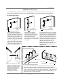
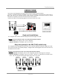
1. ConnectthePVCadaptor*directlyontheexhaustventcollarofthewaterheater.
2. Connecta4”PVCcoupler(or4x3”PVCreducer)tothePVCadaptor.
3. Fromthecoupler(orreducer),continueontherestoftheventrunwith4”PVCpipe(or3”PVC
pipe.)
(ForExhaust)
HorizontalInstallationDiagram
(Withelbowterminations)
HorizontalInstallationDiagram
(With3”PVCConcentricTermination)
Keepa1”cle arancebetweenwall
andtheintakesectionofthe
concentrictermination.Seethe
diagramtotheleft.
‐PVCVentingIllustrations‐
HowtoinstallPVCventingwiththeDirectVentIndoormodels
ConnectionbetweenexhaustventcollarandPVCpiping
Seethenextpageforinstructions.
Wall
ConnectionbetweenexhaustventcollarandPVCpiping
Seethenextpageforinstructions.
Wall
1” minimum
clearance
ConcentricTermination
Insertthebirdscreenincludedwith
thetermination
VerticalInstallationDiagram
Roo
f
RoofFlashing
Firestop

Installation
14│Page
1. Connecta4”PVCStraightpipedirectlyontheintakeventcollarofthewaterheater.
2. Connecta4x3”PVCreducertothe4”PVCStraightpipe.
3. Fromthereducer,continueontherestoftheventrunwith3”PVCpipe.
(ForIntake:4”only)
(ForIntake:
3”only)
Regardingtheclearancesfromtheexhaustterminatorto
theairinletoropening,refertothenextfewpages.
Followallventsystemmanufacturer’sinstructionsandall
localcodes.
Do not common vent or connect any vent from other
appliancestotheDirectVentIndoormodelsvent.
Use 4” Category III/IV approved or Special BH, single or
doublewallstainlesssteelventpipe.
VerticalInstallationDiagram
HorizontalInstallationDiagram
*PVCadaptorisincludedwiththeDirectVentIndoormodels.
4”ventconnectionDiagram
3”ventconnectionDiagram
‐
S
tainlessstee
l
VentingIl
l
ustrations‐
1.Connecta4”PVCStraightpipedirectlyontheintakeventcollarofthewaterheater.
RoofFlashing
Roo
f
RainCap
Firestop
Wall
SidewallVent
Terminator
Exhaustventcollar
oftheDirectVent
Indoormodels
(Female)
PVCadaptor*
4”PVCcoupler
4”PVCStraightpipe
4”PVCStraight
pipe
Intakeventcollar
3”PVCStraightpipe
4x3”PVCreducer
PVCadaptor*
3”PVCStraight
pipe
4x3”PVCreducer
4”PVCStraight
pipe
Intakeventcollar
Exhaustventcollar
oftheDirectVent
Indoormodels
(Female)

Installation
15│Page
‐Ventclearances‐
Canada U.S.A
Directventand
otherthanDirect
Vent
Directvent OtherthanDirectVent
A
Clearanceabovegrade,veranda,porch,deck,
orbalcony.
1foot 1foot 1foot
B
Clearancetowindowordoorthatmaybe
opened.
3feet 1foot
4feetfrombeloworside
opening.1footfrom
aboveopening.
C Clearancetopermanentlyclosedwindow * * *
D
Verticalclearancetoventilatedsoffitlocated
abovetheventterminatorwithinahorizontal
distanceof2feet(61cm)fromthecenterline
oftheterminator.
* * *
E Clearancetounventilatedsoffit * * *
F Clearancetooutsidecorner * * *
G Clearancetoinsidecorner * * *
H
Clearancetoeachsideofcenterlineextended
abovemeter/regulatorassembly
3feet * *
I Clearancetoserviceregulatorventoutlet. 3feet * *
J
Clearancetonon‐mechanicalairsupplyinlet
tobuildingorthecombustionairinlettoany
otherapplication.
3feet 1foot
4feetfrombeloworside
opening.1footfrom
aboveopening.
K Clearancetomechanicalairsupplyinlet. 6feet 3feet 3feet
L
Clearanceabovepavedsidewalkorpaved
drivewaylocatedonpublicproperty.
7feet * 7feet
M
Clearanceunderveranda,porchdeck,or
balcony.
1foot * *
*ForclearancesnotspecifiedinANSIZ223.1/NFPA54orCAN/CSA‐B149.1,pleaseuseclearancesinaccordancewith
localinstallationcodesandtherequirementofthegassupplier.

Installation
16│Page
‐Additionalclearances‐
Pleasefollowalllocalandnationalcodesinregardstoproperterminationclearances.Intheabsenceof
suchcodes,thefollowingclearancescanbeusedasguidelines.Localcodessupersedetheseguidelines.
Forsidewallterminations
Exhausttermination
1ft.
1ft.
2ft.
Inside
corner
Formultiplesidewallexhaust
terminations(e.g.multi‐unit
systems),anexhausttermination
mustbeatleast1ft.awayfrom
anotherexhausttermination.An
exhaustterminationmustalsobe
atleast2ft.awayfromaninside
corner(iftheadjacentwallisless
than2ft.oflength,theminimum
requireddistanceawayfromthe
insidecornerwillbeequaltothe
lengthofthatadjacentwall).
Fordirect‐ventsidewall
terminationsthatusetwo
separatepenetrationsforthe
intakeandexhaust,distance
theintakeandexhaust
terminationsatleast3ft.away
fromeachother,nomatterthe
orientation.
Formultiple‐unit,direct‐ventsidewall
terminationsthatcombinetheintake
andexhaustintoasinglepenetration,
spaceeachdirect‐ventterminationat
least1ft.awayfromeachother,no
mattertheorientation.Adirect‐vent
terminationmustalsobeatleast2ft.
awayfromaninsidecorner(if
the
adjacentwallislessthan2ft.of
length,theminimumrequired
distanceawayfromtheinsidecorner
willbeequaltothelengthofthat
adjacentwall).
Formultiple‐unitrooftopterminations(whetherforstandardindooror
direct‐ventinstallations)spaceallexhaustandintaketerminationsin
accordance
withlocalcodes.Anexhaustterminationmustbespacedfrom
awallorsurfaceinaccordance withlocalcodes aswell.Intheabsenceof
suchacode,anexhaustterminationmustbeahorizontaldistanceofat
least2ft.awayfromawallorsurface.
A:inaccordancewith
localcodes
Forrooftopterminations
Airintake
Exhaust termination
A
A
A
A
A
2ft.
Airintake
Exhaust
termination
Exhaustand/ordirect‐vent
sidewallterminationsshould
beatleast2ft.awayfroman
oppositesurface/wall.Do
notplacethetermination
directlyinfrontofan
openingintoabuilding.
2ft.
Exhaust
termination
Airsupplyinlet
3ft.
3ft.
3ft.
Directventtermination
1ft.
1ft.
Inside
corner
2ft.

Installation
17│Page
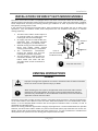
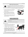
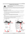
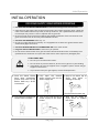
1. Turnoffallelectricpowertothewaterheaterifserviceistobeperformed.
2. Turnthemanualgasvalvelocatedontheoutsideoftheunitclockwisetotheoffposition.
Checkthatthetypeofgasmatchestheratingplatefirst.
Ensure that any and all gas regulators used are operating properly and
providing gas pressures within the specified range shown below. Excess gas
inletpressuremaycauseseriousaccidents.
Conversion of th is unit from natural gas to propane or vise versa will void all
warranty. Contact your local distributor to get the correct unit for your gas
type.Themanufacturerisnotliableforanypropertyand/orpersonaldamage
resultingfromgasconversions.
Sizethegaspipeappropriatelytosupplythenecessaryvolumeofgasrequiredfor
thewaterheaterusingANSI233.1/NFPA54intheUSAorCAN/CSAB149.1inCanada
orlocalcodes.Otherwise,flowcapabilitiesandoutputtemperatureswillbelimited.
GASSUPPLYANDGASPIPESIZING
Theminimumandmaximuminletgaspressuresare:
Gastype Inletgaspressure
NaturalGas Min.5.0”WC–Max.10.5”WC
Propane Min.8.0” WC– Max.14.0” WC
Gas pressure above this specified range for the water heater and/or insufficient gas volume will
adversely affect performance.These pressures are measured when the water heater is in full
operation.
Inlet gas pressure must not exceedthe above maximum values; gas pressure above the specified
rangewillcausedangerous
operatingconditionsanddamagetotheunit.
Until testing of the main gas line supply pressure is completed, ensure the gas line to the water
heaterisdisconnectedtoavoidanydamagetothewaterheater.
‐Gasconnections‐
1. Installamanualgasshut‐offvalvebetweenthewaterheaterandthegassupplyline.
2. When the gas connections are completed, it is nece ssary to perform a gas leak test (see below)
eitherbyapplyingsoapywatertoallgasfittingsandobserving for bubblesorbyusing
agasleak
detectiondevice.
Thewaterheater anditsindividualshutoff valve mu st bedisconnectedfromthegassupply
pipingsystemduringanypressuretestingofthatsystemattestpressuresinexcessof1/2psi
(3.5kPa).
Thewaterheatermustbeisolatedfromthegassupplypipingsystembyclosingitsindividual
manual shutoff valve during any pressure testing of the gas supply piping system at test
pressuresequaltoorlessthan1/2psi(3.5kPa).
3. Alwayspurgethegaslineofanydebrisand/orwater
beforeconnectingtothegasinlet.
WARNING
TOTURNOFFGASTOAPPLIANCE
NOTICE

Installation
18│Page
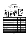
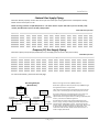
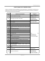
‐NaturalGasSupplyPiping‐
MaximumDeliveryCapacityofCubicFeetofGasperHourofIPSPipeCarryingNaturalGasof0.60SpecificGravity
BasedonPressureDropof0.5”WC
BasedonEnergyContentof1,000BTU/CubicFt.:Thewaterheaterrequires199CubicFt./hrforthe520(T‐H2)
models,and180CubicFt./hrforthe320(T‐H2S)models.
Unit:CubicFeetperHour
PipeSize Length
Diameter 10’ 20’ 30’ 40’ 50’ 60’ 70’ 80’ 90’ 100’ 125’ 150’ 200’
¾” 363 249 200 171 152 138 127 118 111 104 93 84 72
1” 684 470 377 323 286 259 239 222 208 197 174 158 135
1¼” 1,404 965 775 663 588 532 490 456 428 404 358 324 278
1½” 2,103 1,445 1,161 993 880 798 734 683 641 605 536 486 416
2” 4,050 2,784 2,235 1,913 1,696 1,536 1,413 1,315 1,234 1,165 1,033 936 801
‐Propane(LP)GasSupplyPiping‐
MaximumCapacityofPropane(LP)GasBasedon11”WCsupplypressureata0.5”WCpressuredrop
Unit:kBTUperHour
PipeSize
Length
Diameter
10’ 20’ 30’ 40’ 50’ 60’ 70’ 80’ 90’ 100’ 125’ 150’ 200’
¾” 567 393 315 267 237 217 196 185 173 162 146 132 112
1” 1,071 732 590 504 448 409 378 346 322 307 275 252 213
1¼” 2,205 1,496 1,212 1,039 913 834 771 724 677 630 567 511 440
1½” 3,307 2,299 1,858 1,559 1,417 1,275 1,181 1,086 1,023 976 866 787 675
2” 6,221 4,331 3,465 2,992 2,646 2,394 2,205 2,047 1,921 1,811 1,606 1,496 1,260
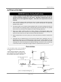
Formoreinformation,pleaseseethenextpage.
BasedonEnergyContentof1,000BTU/CubicFt:
Divideeachappliance’sBTUrequirementby1,000BTUtoget
theappliancesCubicFt.requirement.
Takeintoaccountthedistancetheapplianceisfromthegas
meter,lookintheabovegascharttoproperlysizetheline.
Forsectionsofthegasline
supplyinggastomorethanone
appliance(Ex:PointAtoPointB),addupthecubicft.
requirementsoftheappliancesthatarebeingsuppliedbythat
section,andsizetothefarthestappliance.
ForExample:ThesectionfromAtoBsuppliesgastothe
furnace,range,anddryer.
AddinguptheBTUrequirements
anddividingby1,000yieldsacubicft.requirementof220
cubicft.ofgas.Thefarthestapplianceistherange,whichis50
ft.awayfromthemeter.Lookingattheabovechart,and
underthecolumnof50ft.,SectionAtoBneeds
tobe1”in
ordertosupply220cubicft.
Range
65,000BTU
C
10’Length
1”PipeSize
GasSizingExample
(NaturalGas)
10’Length
3/4”PipeSize
15’Length
1/2”PipeSize
10’Length
1/2”PipeSize
Furnace
120,000BTU
WaterHeater
5’Length
1‐1/4”PipeSize
10’Length
3/4”PipeSize
Dryer
35,000BTU
15’Length
1”PipeSize
5’Length
1‐1/4”PipeSize
GasMeter
B
A
199,000BTU
or
180,000BTU

Installation
19│Page
1.Turnoffallelectricpowertothewaterheaterifserviceistobeperformed.
2.Turnthemanualgasvalvelocatedontheoutsideoftheunitclockwisetothe
off
p
osition.
Do not use this water heater if any part has been submersed under water.
Immediatelycallalicensedprofessionaltoinspectthewaterhe atertoreplace
anydamagedparts.
Donotreverse thehotoutletandcold inletconnections tothewaterheater.
Thiswillnotproperlyactivatethewaterheater.
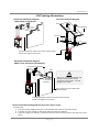
‐Measuringinletgaspressure‐
Thewaterheatercannotperformproperlywithoutsufficientinletgaspressure.Belowareinstructions
onhowtochecktheinletgaspressure.THISISONLYTOBEDONEBYALICENSEDPROFESSIONAL.
1. Shutoffthemanualgasvalveonthesupplygasline.
2. Removethescrewforthe
pressureportlocatedon
thegasinletofthewaterheatershowninthe
diagramtotheright.
3. Connectthemanometertothepressureport.
4. Re‐openthemanualgasval ve.Checktoseethat
therearenogasleaks.Opensomeofthefixtures
thatusethehighest
flowratetoturnonthewater
heater.
5. Checktheinletgaspressure.Whenthewaterheater
isonmaximumburn,themanometershouldread
from5.0”to10.5”WCforNaturalgas,from8.0”to
14.0”WCforPropane.
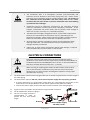
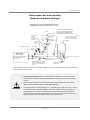
WATERCONNECTIONS
Allpipes,pipefittings,valvesandothercomponents,includingsolderingmaterials,mustbesuitablefor
potablewatersystems.
1. A manual shut off valve mustbeinstalledon the
coldwaterinlettothewaterheaterbetweenthe
mainwatersupplylineandthewaterheater.
2. In addition, a manual
shut off valve is also
recommendedonthehotwateroutletoftheunit.
If the water heater is installed with in, or
subjected to, a closed loop water system, a
thermalexpansiontankmustbeinstalled.
3. Before installing the water heater, flush the
water line to remove all debris,
and after
installation is comp lete, purge the air from the
line.Failuretodosomaycause damagetothe
heater.
4. Thereisawiremeshfilterwithin thecold inlettotrapdebrisfromenteringyourheater.Thiswill
needtobecleanedperiodicallytomaintainoptimumflow.
CAUTION
Pressure
ReliefValve
Hot
outlet
Cold
inlet
Gas
AsCloseas
Possible

Installation
20│Page
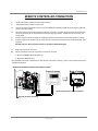
‐Pressurereliefvalve‐
Thewaterheaterhasahigh‐temperatureshutoffswitchbuiltinas a standard safety feature(calleda
Hi‐Limitswitch)thereforea“pressureonly”reliefvalveisrequired.
Thisunitdoesnotcomewithanapprovedpressurereliefvalve.
Anapprovedpressurereliefvalvemustbeinstalled
onthehotwateroutlet.
ThepressurereliefvalvemustconformtoANSIZ21.22orCAN1‐4.4andinstallationmustfollow
localcode.
The discharge cap acity must be at least 199,000 BTU/h for th e 520 (T‐H2) models, and 180,000
BTU/hforthe320(T‐H2S)models.
Thepressurereliefvalveneedstoberatedforamaximumof150psi.
Thedischargepipingforthepressurereliefvalvemustbedirectedsothatthehotwatercannot
splashonanyoneoronnearbyequipment.
Attach the discharge tube to the pressure relief valve and
run the end of the tube to within 6"
from the floor. This discharge tube must allow free and complete drainage without any
restrictions.
Ifthepressurereliefvalveinstalledonthewaterheaterdischargesperiodically,thismaybedue
toadefectivethermalexpansiontankordefectivepressure
reliefvalve.
Thepressurereliefvalvemustbemanuallyoperatedperiodicallytocheckforcorrectoperation.
Novalvemustbeplacedbetweenthereliefvalveandthewaterheater.
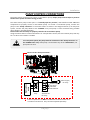
CONDENSATEDRAIN
Thewaterheaterdoesnotincludeabuilt‐incondensateneutralizercartridgeforreducingthepH
levelofcondensatewater.Iflocalcodesdictatethatcondensatemustbeneutralizedpriorto
drainage,acondensateneutralizermustbeinstalled.AnaccessoryNeutralizerassemblyissold
separately.
Intheabsenceof
applicablelocalcodesandregulations,themanufacturerrecommendsthat
condensatebedisposedofintoastandarddrain.Connectadraintubefromthecondensatedrain
port(shownbelow)locatedonthebottomofthewaterheatertoastandarddrain.
Follow all code requirements
of the local authority on
condensate neutralizers and
whether or not they are
requiredfortheinstallation.
Condensatedrainport
Page is loading ...
Page is loading ...
Page is loading ...
Page is loading ...
Page is loading ...
Page is loading ...
Page is loading ...
Page is loading ...
Page is loading ...
Page is loading ...
Page is loading ...
Page is loading ...
Page is loading ...
Page is loading ...
Page is loading ...
Page is loading ...
Page is loading ...
Page is loading ...
Page is loading ...
Page is loading ...
Page is loading ...
Page is loading ...
Page is loading ...
Page is loading ...
Page is loading ...
Page is loading ...
Page is loading ...
Page is loading ...
Page is loading ...
Page is loading ...
Page is loading ...
Page is loading ...
-
 1
1
-
 2
2
-
 3
3
-
 4
4
-
 5
5
-
 6
6
-
 7
7
-
 8
8
-
 9
9
-
 10
10
-
 11
11
-
 12
12
-
 13
13
-
 14
14
-
 15
15
-
 16
16
-
 17
17
-
 18
18
-
 19
19
-
 20
20
-
 21
21
-
 22
22
-
 23
23
-
 24
24
-
 25
25
-
 26
26
-
 27
27
-
 28
28
-
 29
29
-
 30
30
-
 31
31
-
 32
32
-
 33
33
-
 34
34
-
 35
35
-
 36
36
-
 37
37
-
 38
38
-
 39
39
-
 40
40
-
 41
41
-
 42
42
-
 43
43
-
 44
44
-
 45
45
-
 46
46
-
 47
47
-
 48
48
-
 49
49
-
 50
50
-
 51
51
-
 52
52


American Water Heater 520 Owner's manual
- Category
- Water heaters & boilers
- Type
- Owner's manual
- This manual is also suitable for
Ask a question and I''ll find the answer in the document
Finding information in a document is now easier with AI
Other documents
-
A.O. Smith ATI-110-P Technical Documents
-
-
-
Takagi Mobius T-M1 Owner's manual
-
State Water Heaters 710 Installation Manual And Owner's Manual
-
-
State 100282551 User manual
-
-
 The Plumber's Choice 12HCSGE Installation guide
-
 The Plumber's Choice 21GWHS User manual

