
Compared to standard remote controls, the remote control supplied with this receiver has
several operation modes. These modes enable the remote control to control other audio
components. In order to effectively use the remote control it is important to read the
operating instructions and obtain a proper understanding of the remote control and how to
switch its operation modes (etc.).
Using the remote control without completely understanding its design and how to switch
the operation modes may result in incorrect operations.
KRF-A4030
INSTRUCTION MANUAL
B60-4557-00 (EN)
AUDIO RECEIVER
About the supplied remote control (RC-R0708) . . .

Operations
Preparations Other
2
Unpack the unit carefully and make sure that all accessories
are put aside so they will not be lost.
Examine the unit for any possibility of shipping damage. If
your unit is damaged or fails to operate, notify your dealer
immediately. If your unit was shipped to you directly, notify
the shipping company without delay. Only the consignee (the
person or company receiving the unit) can file a claim against
the carrier for shipping damage.
We recommend that you retain the original carton and pack-
ing materials for use should you transport or ship the unit in
the future.
Keep this manual handy for future reference.
Safety precautions
WARNING :
TO PREVENT FIRE OR ELECTRIC SHOCK, DO NOT EXPOSE
THIS APPLIANCE TO RAIN OR MOISTURE.
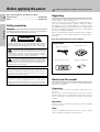
Unpacking
Accessories
FM indoor antenna (1)
AM loop antenna (1)
Batteries (R06/AA) (2)Remote control unit (1)
Before applying the power
Units are designed for operation as follows.
Europe and U.K.................................................................. AC 230 V only
Russia ................................................................................. AC 220 V only
CAUTION: TO REDUCE THE RISK OF ELECTRIC SHOCK, DO NOT
REMOVE COVER (OR BACK). NO USER-SERVICEABLE PARTS
INSIDE, REFER SERVICING TO QUALIFIED SERVICE PERSONNEL.
THE LIGHTNING FLASH WITH ARROWHEAD SYMBOL,
WITHIN AN EQUILATERAL TRIANGLE, IS INTENDED TO
ALERT THE USER TO THE PRESENCE OF UNINSULATED
“DANGEROUS VOLTAGE” WITHIN THE PRODUCT’S ENCLO-
SURE THAT MAY BE OF SUFFICIENT MAGNITUDE TO CONSTI-
TUTE A RISK OF ELECTRIC SHOCK TO PERSONS.
THE EXCLAMATION POINT WITHIN AN EQUILATERAL
TRIANGLE IS INTENDED TO ALERT THE USER TO THE
PRESENCE OF IMPORTANT OPERATING AND MAINTE-
NANCE (SERVICING) INSTRUCTIONS IN THE LITERATURE AC-
COMPANYING THE APPLIANCE.
CAUTION
RISK OF ELECTRIC SHOCK
DO NOT OPEN
Caution : Read this page carefully to ensure safe operation.
How to use this manual
This manual is divided in to three sections, Preparations,
Operations, and Other.
Preparations
Shows you how to connect your audio components to the
receiver.
We've tried to make setting up your system as easy as
possible. However, since this receiver works with all of your
audio components, connecting the system can be fairly
complex.
Operations
Shows you how to operate the various functions available
from the receiver.
Other
Shows you additional information such as “In case of diffi-
culty” (troubleshooting) and “Specifications.”
Maintenance of the set
When the front panel or case becomes dirty, wipe with a soft,
dry cloth. Do not use thinner, benzine, alcohol, etc. for these
agents may cause discoloration.
In regard to contact cleaner
Do not use contact cleaners because it could cause a
malfunction. Be specially careful not to use contact cleaners
containing oil, for they may deform the plastic component.

Operations
Preparations
Other
3
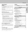
Contents
Before applying the power ................................... 2
Safety precautions ........................................................ 2
Unpacking...................................................................... 2
How to use this manual ................................................ 2
Special features............................................................. 3
Setting up the system............................................. 4
Connecting audio components ..................................... 4
Connecting the antennas .............................................. 5
Connecting the speakers .............................................. 5
Connecting the system control .................................... 6
Names and functions of parts .............................. 7
Main unit ....................................................................... 7
Remote control unit ...................................................... 8
Preparing the remote control ........................................ 9
Normal playback................................................... 10
Preparing for playback................................................. 10
Listening to a source component ............................... 10
Adjusting the sound .................................................... 11
Recording ............................................................... 12
Recording audio .......................................................... 12
Listening to radio broadcasts............................. 13
Tuning (non-RDS) radio stations ................................. 13
Using RDS (Radio Data System) ................................. 13
Using the DISPLAY key .............................................. 14
Presetting RDS stations 13
(RDS AUTO MEMORY) ........................................... 14
Presetting radio stations manually.............................. 15
Receiving preset stations ........................................... 15
Receiving preset stations in order (P.CALL)............... 15
Tuning by program type (PTY search) ........................ 16
Reserving the desired information ............................. 16
In case of difficulty............................................... 18
Specifications ....................................................... 20
Caution : Read the pages marked carefully to ensure
safe operation.
Special features
MONITOR
The TAPE2/MONITOR jacks of this unit accept the connec-
tion of a cassette deck, graphic equalizer, surround proces-
sor, etc. When a 3-head cassette deck is connected to the
TAPE2/MONITOR jacks, it is possible to monitor the sound
which has just been recorded during recording.
@
Station preset
This unit incorporates a function for storing received stations
in preset memory with a simple operation. It is very conve-
nient to preset the stations you like. The preset stations can
be recalled also very easily.
$
RDS (Radio Data System) tuner
#
The receiver is equipped with a RDS tuner that provides several
convenient tuning functions: RDS Auto Memory to automati-
cally preset up to 30 stations including RDS broadcasting
different programs and ordinary FM stations; station name
display to show you the name of the current broadcast station;
and PTY Search to let you tune stations by program type.
PTY (Program TYpe) search
Lets you tune stations by specifying the type of program
you want to hear.
EON (Enhanced Other Networks) reservation
The EON function lets you monitor information on other
stations so you can receive traffic or news programs as
soon as they are broadcast, even they are broadcast on a
station different from the one you are currently listening
to. When the broadcast ends, the receiver returns to the
original station. When listening to KENWOOD source
components connected with system control cords, the
input selector on the receiver automatically switches to
the tuner when a program you desire is broadcast.
Remote controllable audio function
By connecting KENWOOD source components such as a
cassette deck and CD player through system control connec-
tion, the basic operations of these components can be con-
trolled from the remote control unit provided with this unit. A
single remote control unit can control the entire audio system
easily.
New “TRAIT“ transistor
The new developed “TRAIT” transistor with extremely supe-
rior temperature characteristics is used in this amplifier‘s
amplification circuit. Through the use of this transistor, distor-
tion generated because of temperature change is kept to a
minimum resulting in “pure” sound reproduction.
Getting started
Preparations
Operations
Other

Operations
Preparations Other
4
Notes:
1. Be sure to insert all connection cords securely. If their
connections are imperfect, the sound may not be pro-
duced or noise may interfere.
2. Be sure to remove the power cord from the AC outlet
before plugging or unplugging any connection cords. Plug-
ging / unplugging connection cords without disconnecting
the power cord can cause malfunctions and may damage
the unit.
3. Do not connect power cords from components whose
power consumption is larger than what is indicated on the
AC outlet at the rear of this unit.
Microcomputer malfunction
If operation is not possible or an erroneous display ap-
pears, even though all connections have been made
properly, reset the microcomputer referring to “In case of
difficulty”.
*
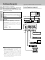
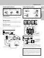
Connecting audio components
To AC wall outlet
CD player
IN
OUT
Record player
SYSTEM CONTROL jacks
6
Shape of AC outlets
IN
OUT
OUT
OUT
Make connections as shown below.
When connecting the related system components, be
sure to also refer to the instruction manuals supplied
with the components you are connecting.
Do not connect the power cord to a wall outlet until all
connections are completed.
Cassette deck or
MD recorder
Cassette deck or
graphic equalizer
@
Setting up the system
Video deck
Monitor TV
OUT
REC OUT
PLAY IN
AUX MD / TAPE1 TAPE2/
MONITOR
PLAY IN REC OUT PLAY IN
PLAY IN
PHONO
CD
L
R
For U.K.
Other countries
CAUTION
Be sure to adhere followings. Or proper ventilation
will be blocked causing damage or fire hazard.
• Do not place any objects impairing heat radiation onto
the top of unit.
• Leave a space around the unit (from the largest outside
dimension including projection) equal or greater than,
shown below.
Top panel : 50 cm
Side panel : 10 cm
Back panel : 10 cm
Caution : Read this page carefully to ensure safe operation.

Operations
Preparations
Other
5
Connecting the antennas
AM Antenna terminal connections
1 Push lever.
AM loop antenna
The supplied loop antenna is for use indoors. Place it as far as
possible from the receiver, TV set, speaker cords and power
cord, and adjust the direction for best reception.
FM indoor antenna
The supplied indoor antenna is for temporary use only. For
stable signal reception we recommend using an outdoor
antenna. Disconnect the indoor antenna when you connect
one outdoors.
FM outdoor antenna
Lead the 75Ω coaxial cable connected to the FM outdoor
antenna into the room and connect it to the FM 75Ω terminal.
AM loop
antenna
FM indoor
antenna
FM outdoor antenna
Use an antenna adaptor
(Commercially available)
1 Strip coating.
2 Push lever.
3 Insert cord. 4 Return lever.
Connecting the speakers
Right
Front Speakers A
Use the FRONT
SPEAKERS B
terminals if you
want to connect a
second front
speaker system.
Left
Setting up the system
2 Insert cord. 3 Return lever.
• Never short circuit the + and – speaker cords.
• If the left and right speakers are connected inversely or the
speaker cords are connected with reversed polarity, the
sound will be unnatural with ambiguous acoustic imaging.
Be sure to connect the speakers correctly.
Speaker impedance
After confirming the speaker impedance indications printed
on the rear panel of the receiver, connect speakers with
matching impedance ratings. Using speakers with a rated
impedance other than that indicated on the rear panel of
the receiver could result in malfunctions or damage to the
speakers or receiver.
FM
75Ω
GND
AM
ANTENNA
SPEAKERS
+
--
+
R
+
--
+
L
LR
B
A
SUBWOOFER
PRE OUT
Front Speakers B
Right
Left
Powered subwoofer
To produce sound from
the powered subwoofer,
turn the SPEAKERS A
key on. No sound will be
produced if only the
SPEAKERS B key is on.

Operations
Preparations Other
6
Connecting the system control
Setting up the system
SYSTEM CONTROL operations
Remote Control
Lets you operate this unit with the system remote sup-
plied with the receiver.
Automatic Operation
When you start playback from a source component, the
input selector on this unit switches to that component
automatically.
Synchronized Recording
Lets you synchronize recording with the start of playback
when recording from CD, MD or analog discs.
Do not connect a system control cord to a cassette
deck connected to the TAPE2/MONITOR jacks.
Connecting system control cords after connecting a
KENWOOD audio component system lets you take
advantage of convenient system control operations.
This unit is compatible only with the [SL-16] mode. The
system control operation is not available if the unit is
connected in the [XS-8], [XS], or [XR] connection
mode.
If your component has the mode select switch, set the
connected components to the [SL16] mode.
[
SL16]
[
SL16] [XS] [XS8] [XR]
[
SL16] [XS] [XS8]
[XS]
SYSTEM
CONTROL
cord
Receiver
Cassette deck
or MD recorder
CD player
Record player
• In order to take advantage of the system control opera-
tions, the components must be connected to the correct
jacks. To use a CD player it must be connected to the CD
jacks. To use a cassette deck (or MD recorder) it must be
connected to the MD/TAPE jacks. When using more than
one CD player (etc.) only the one connected to the
specified jacks may be connected for system control.
• Some CD players and cassette decks are not compatible
with the [SL16] system control mode.
• Some MD players are not system control compatible.
You cannot make system control connections to this
kind of equipment.
Notes
1. [SL16] equipment cannot be combined with [XR], [XS],
and [XS8] equipment for system operations. If your
equipment consists of this kind of combination, please do
not connect any system control cords. Even without
system control cords, normal operations can be carried
out without effecting performance.
2. Do not connect system control cords to any components
other than those specified by KENWOOD. It may cause
a malfunction and damage your equipment.
3. Be sure the system control plugs are inserted all the way
in to the system control terminals.
EXAMPLE: [SL16] mode connections
The underlined portion represents the setting of the system
control mode.
SYSTEM CONTROL cord
SYSTEM CONTROL

Operations
Preparations
Other
7
A SPEAKERS B
STANDBY
POWER
MULTI CONTROL
SOUND
SOURCE DIRECT
AUTOBAND MEMORY
INPUT SELECTOR
VOLUME CONTROL
UPDOWN
BALANCE
PTY TA/NEWS DISPLAY
PHONES
ON/STANDBY
ON OFF
STEREO
TUNED
AUTO
SP.
TI. V
O
L
S.DI
R
ECT
TAPE 2/MONI
TPTA NEWS PTY
****** **.
MHz
kHz
A B MUTE
MEMOMEMO
EON
FM
AM
TAPE 2/MONITOR
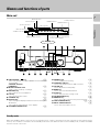
Display
AUTO indicator
TUNED indicator
Standby mode
While the standby indicator of the unit is lit, a small amount of current is flowing into the unit’s internal circuitry to back up the
memory. This condition is referred to as the standby mode of the unit. While the unit is in the standby mode, it can be turned ON
from the remote control unit.
Speaker indicators
S.DIRECT indicator
TAPE 2/ MONI indicator
1 ON/STANDBY ( ) key 0
Use to switch the power ON/STANDBY when the POWER
is turned ON.
STANDBY indicator
POWER key
0
2 MULTI CONTROL knob
Used to make a variety of settings.
3 BALANCE key
!
Use to adjust the sound balance.
4 PTY key
^
Use to perform PTY search.
5 TA/NEWS key
&
6 DISPLAY key $
Use to change the display indications when receiving RDS
broadcasts.
Use to adjust the brightness of the display.
7 VOLUME CONTROL knob
0
8 PHONES jack !
Use for headphone listening.
9 SPEAKERS A B keys
0
Use to turn speaker system A/B on and off.
0 SOUND key
!
Use to adjust the sound quality.
! BAND key
#
Use to select the broadcast band.
@ AUTO key
#
Use to select the auto tuning mode.
# SOURCE DIRECT key
!
$ MEMORY key $
Use to store radio stations in the preset memory.
% TAPE 2/MONITOR key
0 @
^ INPUT SELECTOR knob 0
Use to select the input sources.
MUTE indicator
Names and functions of parts
MEMO indicator
STEREO indicator
Frequency display, Input display,
Preset channel display
Band indicators
RDS indicator
RDS indicator
Main unit

Operations
Preparations Other
8
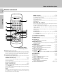
Remote control unit
1 Numeric keys (1~0, +10)
If CD or MD is selected as the input source, these keys
function as numeric keys. If tuner is selected as the input
source, these keys are used to call up station presets.
2 Component operation keys
Use these keys to operate other components with system
control connections to the receiver.
TUNING (1 ¡) keys
#
If tuner is selected as the input source, these keys func-
tion as tuning keys.
If CD or MD is selected as the input source, these keys
function as search keys.
P.CALL (4 ¢) keys
%
If tuner is selected as the input source, these keys func-
tion as P.CALL keys.
If CD or MD is selected as the input source, these keys
function as skip keys.
2 key
If tape is selected as the input source, this key functions
as the play key for side B of the cassette (the side facing
away from the front of the deck).
BAND (6) key
#
If tuner is selected as the input source, this key functions
as the band selector key.
If CD is selected as the input source, this key functions as
the play/pause key.
If MD is selected as the input source, this key functions as
the play key.
DISC SKIP, A/B, +100 key
If CD is selected as the input source, this key functions as
the multi-CD player disc skip key.
If TAPE is selected as the input source, this key is used to
switch between the two decks (A and B) of a double
cassette deck.
If MD is selected as the input source, this key function as
numeric key.
AUTO(7) key
#
If tuner is selected as the input source, this key functions
as the AUTO key.
If CD or MD is selected as the input source, this key
functions as the stop key.
3 VOLUME UP, DOWN keys
0
4 MEMORY key $
Use to store radio stations in the preset memory.
5 SOUND key
!
Use to adjust the sound quality.
6 BASS BOOST key
!
Use to select the maximum adjustment setting for the low
frequency range.
7 DIMMER key
$
Use to adjust the brightness of the display.
8 Input selector keys
0
Use to select the receiver’s input source.
9 RDS operation keys
#
Use to receive RDS broadcasts.
0 POWER (
)key 0
Use to switch the power ON/STANDBY when the POWER
is turned ON.
! S.DIRECT key
!
@ MUTE key !
Use to temporarily mute the sound.
# MULTI CONTROL keys
Used to make a variety of settings.
$ BALANCE key
!
Use to adjust the sound balance.
% TAPE2/ MONITOR key
0@
Names and functions of parts
Model: RC-R0708
Infrared ray system
DIMMER
BASS BOOST
TUNER CD
1 2 3
4 5 60
7 8 9 +10
TAPE2/
MONITOR
TA/NEWSPTY DISPLAY AUX
MULTI CONTROL
MD/TAPE1
REMOTE CONTROL UNIT
RC-R0708
8
PHONO
6 7
¡
2
TUNING
DISC SKIP
%
VOL. DOWN
VOL. UP
MEMORY
S.DIRECT
SOUND BALANCE
fi
1 ¢
P.CALL
4
BAND AUTO
A/B +100
POWER
1
2
#
3
4
5
6
7
0
!
$
%
@
9
fi
fi
MUTE

Operations
Preparations
Other
9
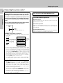
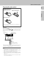
Loading the batteries
Preparing the remote control
Notes:
1. The supplied batteries may have shorter lives than ordinary
batteries due to use during operation checks.
2. When the remote-controllable distance gets shorter than
before, replace both batteries with new ones.
3. Placing the remote sensor in direct sunlight, or in direct
light from a high frequency fluorescent lamp may cause a
malfunction.
In such a case, change the location of the system installa-
tion to prevent malfunction.
Model: RC-R0708
Infrared ray system
• When pressing more than one remote control key succes-
sively, press the keys securely by leaving an interval of 1
second or more between keys.
Operation
Operating range
(Approx.)
1 Remove the cover.
2 Insert the batteries.
3 Close the cover.
• Insert two AA-size (R06) batteries as indicated by the
polarity markings.
Names and functions of parts
When the “STANDBY” indicator is lit, the power turns ON
when you press the POWER (
) key on the remote control.
When the power comes ON, press the key you want to
operate.
Remote sensor
30˚
6 m
30˚

Operations
Preparations Other
10
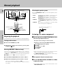
Preparing for playback
Some preparatory steps are needed before starting playback.
Turning on the receiver
1 Turn on the POWER key to ON.
2 Turn on the power to this receiver by pressing ON/
STANDBY (
) key.
Selecting MD/TAPE 1 (Main unit only)
Select the source name corresponding to the component
connected to the MD/TAPE1 jacks. The initial factory setting
is “TAPE 1”. To change the source name associated with the
MD/TAPE1 jacks to “MD”, follow the steps below:
1 Use the INPUT SELECTOR knob to select “TAPE 1”.
2 Hold down the AUTO key for more than 2 seconds.
• The source indication changes to “MD”.
• To return to the original indication, repeat the above
procedure.
Selecting the speaker system
Press the SPEAKERS A or B key to select the speaker system
to be used.
A ON : Sound from the speakers connected to the
SPEAKERS A terminals on the rear panel.
B ON : Sound from the speakers connected to the
SPEAKERS B terminals on the rear panel.
A+B ON : Sound from both the speakers connected to
the SPEAKERS A and B terminals on the rear
panel.
A+B OFF : No sound from the speakers. Use this setting
when listening with headphones.
Listening to a source component
1
Use the input selector (INPUT SELECTOR) to select
the source you want to listen to.
The input sources change as shown below:
Selecting a source using the INPUT SELECTOR
1 TUNER (frequency display)
2 “CD”
3 “TAPE 1” or “MD”
4 “PHONO”
5 “AUX”
• When selecting an input source by using the remote
control , press the desired input selector key.
• The INPUT SELECTOR on the front panel of the receiver
always cycles through all inputs.
2
Start playback from the selected source.
3
Use the VOLUME CONTROL (VOLUME UP , DOWN)
to adjust the volume.
• The sound of input source cannot be listened to with
TAPE2/MONITOR is ON.
The indicator for the speakers you
want to use should be lit.
Normal playback
SP. A B
MULTI CONTROL
INPUT SELECTOR
BASS BOOST
SOUND
MUTE
POWER
S. DIRECT
BALANCE
VOLUME UP, DOWN
INPUT SELECTOR
MULTI CONTROL
SOUND
BALANCE
SPEAKERS A B
POWER
ON/STANDBY
AUTO
SOURCE DIRECT
VOLUME CONTROL

Operations
Preparations
Other
11
Blinks
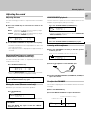
Adjusting the sound
Adjusting the tone
Use the following procedure to adjust the bass and treble
levels.
1 Press the SOUND key to select the tone mode to be
adjusted.
BASS : Select this to adjust the low frequency range.
(Press the SOUND key once.)
TREBLE: Select this to adjust the high frequency range.
(Press the SOUND key twice.)
2 Use the MULTI CONTROL to adjust the sound quality.
• The bass and treble levels are adjustable from -10 to +10
in 2 step increments.
• The adjustment item is displayed for approximately 8
seconds.
Once-touch low frequency emphasis
(BASS BOOST) (Remote control only)
Use the following procedure to emphasize the bass and
create a richer sound.
Press the BASS BOOST key.
• Press the BASS BOOST key once to select the maxi-
mum (+10) low frequency emphasis setting.
Switching back to the previous setting
Press the BASS BOOST key again.
Muting the sound (Remote control only)
MUTE lets you mute the sound of the speakers.
Press the MUTE key.
• Muting can also be cancelled by adjusting the volume.
To cancel
Press the MUTE key again so that the “MUTE”
indicator goes off.
Listening with headphones
1 Press the SPEAKERS A or B key so that the speaker
indicator goes off.
2 Connect headphones to the PHONES jack.
3 Use the VOLUME CONTROL (VOLUME UP, DOWN) to
adjust the volume.
To adjust the BALANCE
The mode for adjusting the volume balance between the left
and right.
1 Press the BALANCE key.
2 Use the MULTI CONTROL to adjust the balance.
PHONES
Make sure the SPEAKERS indicators are turned off.
Indicates the center.
Indicates the balance setting.
SOURCE DIRECT playback
Use this function to pass the source material direct to the
amplifier, by passing any audio processing.
Press the SOURCE DIRECT (S.DIRECT) key.
• Switch to another input source to cancel SOURCE DI-
RECT (S.DIRECT) playback.
To cancel
Press the SOURCE DIRECT (S.DIRECT) key again.
Normal playback
SP.
BAss +4
A B
SP.
BAss + 1)
A B
SP.
TAPE1
A MUTEB
TAPE1
S.DI
R
ECT
SP.
A B
SP.
TAPE1
L-- t
SP. A B
-R

Operations
Preparations Other
12
Recording audio
Recording a music source
1 Use the input selector (INPUT SELECTOR) to select
the source (other than “TAPE 1”) you want to record.
2 Set the cassette deck to record.
3 Start playback, then start recording.
Copying tapes
TAPE 1 = TAPE 2 copying
1 Use the input selector to select “TAPE 1”.
2 Start playback on the cassette deck connected to the
MD/TAPE1 jacks and start recording on the cassette
deck connected to the TAPE2/MONITOR jacks.
• To copy tapes using a double cassette deck, refer to the
instruction manual of the double cassette deck.
TAPE2/MONITOR function
You can connect a cassette deck or graphic equalizer to
the TAPE2/MONITOR jacks of the receiver. If a graphic
equalizer is connected, the TAPE2/MONITOR key should
be left in the on position. Alternately, if a cassette deck
equipped with a 3-head system is connected to theTAPE2/
MONITOR jacks, you will be able to monitor the just-
recorded signal while making recordings on the cassette
deck. By switching the TAPE2/MONITOR key on and off,
you can compare the sound of the source signal and the
just-recorded signal. For more information, refer to the
instruction manual of the connected component.
• The equalizer effect can be applied to the played
audio but cannot be recorded together with the
audio signal.
• Copy from “TAPE 2” to ”TAPE 1“ is not possible.
Input level adjustment
(when using the monitor function)
If the input level while using the monitor function is too high,
adjust the input level as described below.
The input level cannot be adjusted when in the source direct
playback mode.
1 Press the TAPE2/MONITOR key.
2 Press the SOUND key several times until the “INPUT”
indication appears.
3 Use the MULTI CONTROL to adjust the input level.
• The adjustment mode is displayed for approximately 8
seconds.
• The input level may be adjusted to any one of 2 settings:
0 and -6. (The initial setting is 0.)
4 Press the SOUND key to return to the input indication.
Recording
SP.
INPUT -6
A B
FW
TAPE 2/MONI
MULTI CONTROL
SOUND
TAPE2 /MONITOR
INPUT SELECTOR
MULTI CONTROL
TAPE2 /MONITOR
SOUND
INPUT SELECTOR

Operations
Preparations
Other
13
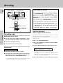
Listening to radio broadcasts
Tuning (non-RDS) radio stations
Radio stations can be classified into RDS (Radio Data System)
stations and other stations. To listen to or store RDS stations
in the preset memory, see the section entitled, “Using RDS”.
Frequency display
1
Use the input selector (INPUT SELECTOR) to select
the tuner.
2
Use the BAND key to select the desired broadcast
band.
Each press switches the band as follows:
3
Use the AUTO key to select the desired tuning
method.
Each press switches the tuning method as follows:
• Normally, set to “AUTO”(auto tuning). If the radio
waves are weak and there is a lot of interference, switch
to manual tuning. (With manual tuning, stereo broad-
casts will be received in monaural.)
4
Use the MULTI CONTROL to select the station.
Auto tuning :The next station is tuned automatically.
Manual tuning :Turn the knob (press the key) to select
the desired station.
• You can also use the TUNING key on the remote control
to make the selection.
Lights when a broadcast is being received in stereo.
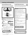
Using RDS (Radio Data System)
RDS is a system that transmits useful information (in the form
of digital data) for FM broadcasts along with the broadcast
signal. Tuners and receivers designed for RDS reception can
extract the information from the broadcast signal for use with
various functions, such as automatic display of the station
name.
RDS functions:
PTY (Program TYpe identification) Search ^
Automatically tunes to a station that is currently broad-
casting the specified program type (genre).
EON (Enhanced Other Network) reservation
^
Sets the tuner to automatically switch to stations broad-
casting one of two types of programs, even though you are
listening to another station. The tuner returns to the
original station when the broadcast of the selected pro-
gram ends.
PS (Program Service name) Display
Automatically displays the station name transmitted by
the RDS station.
RDS Auto Memory function
$
Automatically selects and stores up to 30 RDS stations in
the preset memory.
If fewer than 30 RDS stations have been stored in the
preset memory, regular FM stations will be stored in the
remaining places.
Radio Text function
Displays the radio text data transmitted by some RDS
stations when you press the DISPLAY key. There is no
display if no text data was transmitted.
TI volume
&
If you preset the volume level, you can listen to the
information of your choice at that volume level automati-
cally. After the information has been received, the volume
returns to the previous level.
The ”RDS“ indicator lights up when an RDS broadcast (signal)
is received.
Note:
Some functions and function names may differ for cer-
tain countries and areas.
Before using a function utilizing the RDS, be sure to
perform the RDS Auto Memory operation by referring to
the description in “Presetting RDS stations (RDS AUTO
MEMORY)”.
$
SP.
A B
FM
AM
STEREO
AUTO
))
.
MHz
STEREO
TUNED
AUTO
SP.
-- 89 )).
MHz
A B
FM
STEREO
TUNED
AUTO
SP.
TP
BBC 1F M
MHz
kHz
A B MUTE
EON
FM
AM
S.DI
R
ECT
TAPE 2/MONI
“FM“ or “AM” indicator
1 FM
2 AM
1 AUTO lit (auto tuning)
2 AUTO not lit (manual tuning)
”TUNED“ is
displayed when
a station is
received
MULTI CONTROL
VOLUME UP, DOWN
1~0, +10
BAND
AUTO
PTY
DISPLAY
TA/NEWS
4 P.CALL ¢
DIMMER
INPUT SELECTOR
MULTI CONTROL
AUTO
BAND
MEMORY
PTY DISPLAY
TA/NEWS
INPUT SELECTOR

Operations
Preparations Other
14
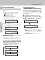
Using the DISPLAY key
Pressing the DISPLAY key changes the contents of the
display.
Each press switches the display mode as follows:
1 PS (Program Service name) display
2 RT (Radio Text) display
3 Frequency display
1 PS (Program Service name) display:
The station name is displayed automatically when an RDS
broadcast is received,
If no PS data was sent, “NO PS” is displayed.
2 RT (Radio Text) display:
Text data accompanying the RDS broadcast scrolls across
the display. “NO RT” or “RT----” is displayed if the current
RDS station does not provide RT data.
3 Frequency display:
Displays the frequency of the current station.
Display dimmer adjustment
The dimmer function lets you select the brightness of the
receiver's display. You might find this useful if you darken
your room to watch movies or listen to music.
Each time you hold down the DISPLAY key of the main
unit for more than 2 seconds, the display brightness
changes among the three available settings. Select the
brightness level you find most pleasing.
The same function as above is also available by pressing
the DIMMER key of the remote control unit.
Presetting RDS stations
(RDS AUTO MEMORY) (Main unit only)
This function automatically stores up to 30 stations including
the RDS stations and ordinary FM stations in the preset
memory. In order to use the EON and PTY functions, the RDS
stations must be stored in the preset memory using the RDS
AUTO MEMORY function.
1
Use the INPUT SELECTOR to select the tuner.
2
Use the BAND key to set the broadcast band to
“FM”.
3
Press and hold the MEMORY key for more than 2
seconds.
• After a few minutes, up to 30 RDS stations are preset in
order from channel “01”.
• Stations already stored in the preset memory may be
replaced by RDS stations. (i.e., If the RDS AUTO
MEMORY function finds 15 RDS stations, the stations
currently preset at numbers 01~15 are replaced by the
RDS stations.)
• The RDS AUTO MEMORY may take a few minutes to
preset stations.
Listening to radio broadcasts
STEREO
TUNED
AUTO
SP.
TP
BBC 1F M
MHz
kHz
A B MUTE
EON
FM
AM
S.DI
R
ECT
TAPE 2/MONI
STEREO
TUNED
AUTO
SP.
TP
-- 1)) 4).
MHz
kHz
A B MUTE
EON
FM
AM
S.DI
R
ECT
TAPE 2/MONI
STEREO
TUNED
AUTO
SP.
TP
ABCDEF GH
MHz
kHz
A B MUTE
EON
FM
AM
S.DI
R
ECT
TAPE 2/MONI
STEREO
TUNED
AUTO
SP.
TP
AUTO
MHz
kHz
A B MUTE
EON
R.D.S
FM
AM
S.DI
R
ECT
TAPE 2/MONI
STEREO
TUNED
AUTO
SP.
TP
MEMORY
MHz
kHz
A B MUTE
EON
R.D.S
FM
AM
S.DI
R
ECT
TAPE 2/MONI
j
SP.
TAPE1
A B
SP.
TAPE1
A B
SP.
TAPE1
A B

Operations
Preparations
Other
15
Blinks for 5 seconds
Lights for 5 seconds
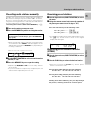
Receiving preset stations
1
Use the input selector (INPUT SELECTOR) to select
the tuner.
2
Using the remote control unit, enter the number of
the preset you want to receive (up to ”30“).
Press the numeric keys in the following order:
For ”15“, press .......... 0,5
For ”20“, press .......... 0,0,)
• If you make a mistake entering a two digit number, press
the 0 key several times to return to the original
display and start again.
Receiving preset stations in order
(P.CALL)
1
Use the input selector (INPUT SELECTOR) to select
the tuner.
2
Use the P.CALL key to select the desired station.
• Each time you press the P.CALL key, another preset
station is received in order.
Pressing the P.CALL (¢) key does the following:
01=02=03=
....
28=29=30=01=02=03=
Pressing the P.CALL (4) key does the following:
01+02+03+
....
28+29+30+01+02+03+
Holding down the P.CALL key, lets you skip through
the presets, receiving each for 0.5 seconds apiece.
Presetting radio stations manually
The RDS auto memory function assigns preset numbers to
RDS stations starting from preset number ”01“. Therefore,
be sure to execute the RDS auto memory function before
using the following operations to manually store AM stations
and other FM stations, and RDS stations.
“Presetting RDS stations (RDS AUTO MEMORY)”.
$
1
Tune to the station you want to store.
2
Press the MEMORY key while receiving the station.
Proceed to step 3 within 5 seconds.
(If more than 5 seconds elapse, press the MEMORY
key again).
• When storing radio stations manually, it may take a few
seconds before the “MEMO” indicator appears in the
display after pressing the MEMORY key depending on
receiving conditions.
3
Use the MULTI CONTROL to select one of the station
presets (1 – 30).
4
Press the MEMORY key to accept the setting.
• Repeat steps 1, 2, 3 and 4 to store as many stations
as necessary.
• If you store a station at a previously used preset, the old
station will be replaced by the new one.
Listening to radio broadcasts
STEREO
TUNED
AUTO
SP.
01 89 )).
MHz
A B
FM
MEMO
STEREO
TUNED
AUTO
SP.
15 9) )).
MHz
A B
FM

Operations
Preparations Other
16
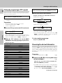
Tuning by program type (PTY search)
This function lets you set the tuner to automatically search for
stations which are currently broadcasting the type of program
(genre) you want to listen to.
Under certain receiving conditions, it may take more
than 1 minute to complete the search.
• PTY search cannot be activated during EON override
reception.
Preparations
• Execute the RDS auto memory procedure.
• Set the broadcast band to ”FM“.
• Tune to a RDS station.
1
Press the PTY key to activate the PTY search mode.
When a RDS broadcast is received, the program type is
shown on the display. If no PTY data is available, or if the
station is not a RDS station, ”NONE” is displayed.
2
While the “PTY” indicator is lit, use the MULTI
CONTROL to select the program type of your choice.
Program type table
Program Type Name Display
Pop Music POP M
Rock Music ROCK M
Easy Listening Music EASY M
Light Classical LIGHT M
Serious Classical CLASSICS
Other Music OTHER M
News NEWS
Current Affairs AFFAIRS
Information INFO
Sport SPORT
Education EDUCATE
Drama DRAMA
Culture CULTURE
Science SCIENCE
Varied VARIED
Weather WEATHER
Finance FINANCE
Children’s programs CHILDREN
Social Affairs SOCIAL
Religion RELIGION
Phone In PHONE IN
Travel TRAVEL
Leisure LEISURE
Jazz Music JAZZ
Country Music COUNTRY
National Music NATION M
Oldies Music OLDIES
Folk Music FOLK M
Documentary DOCUMENT
“NO PROG” is displayed if this operation is attempted
before performing the RDS AUTO MEMORY operation.
3
Press the PTY key to start searching.
Example: Searching for a Rock Music broadcast.
• No sound is heard while “PTY” is blinking.
• If the desired program type cannot be found, “NO
PROG” is displayed, then after several seconds the
display returns to the original display.
To select another program type
Repeat steps 1, 2 and 3.
Reserving the desired information
When the receiver is tuned to a RDS EON station (a station at
which the “EON” indicator lights up), this function lets you
set the receiver to automatically switch stations to receive
news or traffic programs as they are broadcast. When the
broadcast is over, the receiver returns to the original station
automatically.
Preparation
• Set the broadcast band to ”FM”. #
1
Complete steps
1
~
3
of ”Presetting RDS stations
(RDS AUTO MEMORY)“.
$
Skip this step if you have already completed the
RDS AUTO MEMORY procedure.
• The EON function will not work if all 30 FM preset
stations were stored manually using the procedure shown
in “Presetting radio stations manually”.
%
Be sure to use the RDS AUTO MEMORY function.
Continued to next page
Goes out
Station name display
Blinks
Program type name display
Display while searching
Display when a station is received.
STEREO
TUNED
AUTO
SP.
TPTA PTY
NEWs
MHz
kHz
A B MUTE
EON
FM
AMTI. V
O
L
S.DI
R
ECT
TAPE 2/MONI
STEREO
TUNED
AUTO
SP.
PTY
ROCK M
MHz
kHz
A B MUTE
EON
FM
AM
S.DI
R
ECT
TAPE 2/MONI
STEREO
TUNED
AUTO
SP.
TP PTYPTY
BBC 1F M
MHz
kHz
A B MUTE
EON
FM
AM
S.DI
R
ECT
TAPE 2/MONI
Blinks for 2 seconds
Listening to radio broadcasts

Operations
Preparations
Other
17
When waiting for information while listening
to a RDS station without the EON function
If the “EON” indicator does not light in steps 3 and 4 and
the desired kind of information has already been selected,
the information from only the station being received will
be waited for.
TP (Traffic Program) indication
When the “TP” indicator is lit, this means that the pres-
ently-received station or a station in the same network is
transmitting traffic information. When “TP” is displayed
for the station being received, the traffic information of
this station can be received without EON reservation.
To cancel
Press the TA/NEWS key again.
Setting the volume while receiving information
(TI volume) (Main unit only)
If you preset the volume level, you can listen to the informa-
tion of your choice at that volume level automatically. After
the information has been received, the volume returns to the
previous level.
1 Hold down the TA/NEWS key for more than 2
seconds so that the “TI.VOL” indicator starts blink-
ing.
2 Use the VOLUME CONTROL knob to select the
desired volume level.
Proceed to next step within 5 seconds.
3 Press the TA/NEWS key to enter the new setting.
• The “TI.VOL” indicator stops blinking and remains lit.
To cancel
Hold down the TA/NEWS key for more than 2 seconds
so that the “TI.VOL” indicator goes off.
Blinks
2
Press the TA/NEWS key to select the information
type of your choice.
”TP“ lights for stations where TP (Traffic Program) information
can be received.
Each press switches the reservation mode as fol-
lows:
• If “TA” and “NEWS” can not be selected, carry out the
“Presetting RDS stations (RDS AUTO MEMORY)”
again.
$
3
Tune to a preset RDS station.
Choose a RDS preset station that displays both the
“RDS” and “EON” indicators.
• If you want to reserve TA, receive a station with which
the “TP” indicator lights.
When “EON” does not light although an RDS station is
received, that station is not transmitting EON data.
Please select a different station.
4
Wait for the information you selected while listen-
ing to the current station.
The receiver will wait for the desired information to start
as long as the tuner is set to a preset RDS station that
displays both the “EON” and “RDS” indicators.
When listening to the tuner:
Be sure to stay tuned to stations that display both the
“EON” and “RDS” indicators.
To listen sources other than the tuner:
1. Tune in a station which that displays both the “EON”
and “RDS” indicators, then use the INPUT SELECTOR
to switch the input to the source you desire.
2. Even when the INPUT SELECTOR is set to a source
other than tuner, it will automatically switch to tuner
when the desired EON program starts to broadcast.
During this period, the source selected in step 1 contin-
ues playing, but will not be heard.
3. When reception of the desired EON program is com-
plete, the INPUT SELECTOR returns to the previous
input source.
•If a reserved EON program starts to broadcast during
recording, the INPUT SELECTOR switches to the tuner
and the station broadcasting the EON program is re-
corded.
•Do not use the EON function during recording.
Display When ”TA“ is selected
1 TA (Traffic Announcement)
2 NEWS (News)
3 TA, NEWS (Traffic Announcement and News)
4 Goes off (EON off)
STEREO
TUNED
AUTO
SP.
TPTA PTYPTY
BBC 1F M
MHz
kHz
A B MUTE
EON
FM
AM
S.DI
R
ECT
TAPE 2/MONI
STEREO
TUNED
AUTO
SP.
TPTA PTYPTY
NOW TA
MHz
kHz
A B MUTE
EON
FM
AM
S.DI
R
ECT
TAPE 2/MONI
STEREO
TUNED
AUTO
SP.
TPTA PTYPTY
TI -66 dB
MHz
kHz
A B MUTE
EON
FM
AMTI. V
O
L
S.DI
R
ECT
TAPE 2/MONI
Display When “TA” is selected
Be sure “EON” appears in the display
Listening to radio broadcasts

Operations
Preparations Other
18
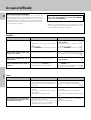
Resetting the Microcomputer
If the microcomputer may malfunction (unit cannot be
operated, or shows an erroneous display) if the power cord
is unplugged while the power is ON, or due to some other
external factor. If this happens, execute the following pro-
cedure to reset the microcomputer and return the unit to its
normal operating condition.
Amplifier
Cause
• The speaker cords are disconnected.
• VOLUME is set to the minimum posi-
tion.
• MUTE is ON.
• The SPEAKERS switches are set to OFF.
• Speaker cords are short-circuited.
• The speaker cord is disconnected.
• The audio cord from the turntable is not
connected to the PHONO jacks.
• The turntable is not grounded.
Remedy
• Connect properly referring to “Setting
the speakers”.
5
• Adjust the volume to a proper level.
• Turn OFF the MUTE. !
• Set the SPEAKERS switch(es) to ON.
0
• Turn the power off, eliminate the short-
circuiting, then turn on the power again.
5
• Connect properly referring to “Setting
the speakers”. 5
• Insert the audio cord plugs securely into
the PHONO jacks.
• Connect the grounding wire to the GND
terminal on the rear panel. 4
With the power cord plugged in, turn the POWER key
OFF. Then, while holding down the ON/STANDBY
key, press the POWER key.
• Please note that resetting the microcomputer will clear
the contents of the memory and returns the unit to the
state it was in when it left the factory.
In case of difficulty
Tuner
Cause
• No antenna is connected.
• The broadcast band is not set properly.
• The frequency of the desired station is
not tuned.
• Noise due to ignition noise from an auto-
mobile.
• Noise due to interference from an elec-
tric appliance.
• Noise due to a nearby TV set.
• The preset station belongs to a frequency
that cannot be received.
• The preset memory was cleared be-
cause the power cord had been un-
plugged for a long period of time.
Remedy
• Connect an antenna.
5
• Set the broadcast band properly.
• Tune the frequency of the desired sta-
tion. #
• Install the outdoor antenna away from
the road.
• Turn off the power to the appliance.
• Install the receiver farther away from the
TV.
• Preset a station with a receivable fre-
quency.
• Preset the station again.
Symptom
Radio stations cannot be received.
Interference.
A station which was preset cannot
be received by pressing the corre-
sponding numeric key.
Symptom
No sound from the speakers.
The standby indicator blinks and
sound is not output.
Sound is not output from one of
the speakers.
A humming noise is generated
when the PHONO input selector is
selected.

Operations
Preparations
Other
19
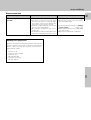
Remote control unit
Cause
• Batteries are exhausted.
• The remote control unit is too far away
from the main system, controlling angle
is too large, or there is an obstacle be-
tween the receiver and the remote.
• The audio cords and system control cords
are not connected properly.
• No software is loaded in the source
component.
• An attempt is made to play a tape which
is being recorded in the cassette deck.
Remedy
• Replace with new batteries. 9
• Operate the remote control unit within
the controllable range.
• Connect properly referring to “Setting
up the system”. 46
• Place software in the source component
you want to play.
• Wait until recording has completed.
Symptom
Remote control operation is not
possible.
Memory back up function
Please note that the following items will be deleted from
the unit's memory if the power cord is disconnected from
the AC outlet or the main power switch is turned off for
approximately 3 days.
• Power mode
• Input selector settings
• Volume level
• Broadcast band
• Frequency setting
• Preset stations
In case of difficulty

Operations
Preparations Other
20
For your records
Record the serial number, found on the back of the unit, in
the spaces designated on the warranty card, and in the
space provided below. Refer to the model and serial
numbers whenever you call upon your dealer for informa-
tion or service on this product.
Model Serial Number
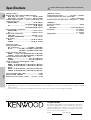
Specifications
[ AUDIO section ]
Rated power output during STEREO operation
(DIN) 1 kHz, 0.7 % at 4 Ω ........................ 105 W + 105 W
(IEC) 63 kHz ~ 12.5 kHz, 0.5 % at 4 Ω..100 W + 100 W
Total harmonic distortion ....... 0.02 % (1 kHz, 50 W, 4 Ω)
Signal to noise ratio
PHONO (MM) .......................................... 75 dB (IHF'66)
55 dB (DIN 50mW output)
CD ............................................................. 92 dB (IHF'66)
56 dB (DIN 50mW output)
Input sensitivity / impedance
PHONO (MM) ........................................ 2.5 mV / 27 kΩ
CD .......................................................... 200 mV / 47 kΩ
Output level / impedance
TAPE REC ............................................ 200 mV / 2.2 kΩ
PRE OUT (SUBWOOFER) ........................... 2 V / 2.2 kΩ
Tone control
BASS ...................................................±9 dB (at 100 Hz)
TREBLE ...............................................±9 dB (at 10 kHz)
[ FM tuner section ]
Tuning frequency range
U.K. and Europe ........................ 87.5 MHz ~ 108.0 MHz
Russia............... 87.5 MHz ~ 108.0 MHz (10 kHz STEP)
65.0 MHz ~ 74.0 MHz (50 kHz STEP)
Usable sensitivity (DIN, 75 Ω)
MONO ..... 1.2 µV / 13.2 dBf (40 kHz DEV., S/N 26 dB)
STEREO.... 45 µV / 44.2 dBf (46 kHz DEV., S/N 46 dB)
Total harmonic distortion (DIN, 1 kHz)
MONO .......................................... 0.2% (65.2 dBf input)
STEREO........................................ 0.8% (65.2 dBf input)
Signal to noise ratio (DIN weighted, 1 kHz)
U.K. and Europe
MONO .... 65 dB (40 kHz DEV., S/N 26 dB, 65.2 dBf input)
STEREO . 58 dB (46 kHz DEV., S/N 46 dB, 65.2 dBf input)
Russia
MONO ... 63 dB (40 kHz DEV., S/N 26 dB, 65.2 dBf input)
STEREO . 58 dB (46 kHz DEV., S/N 46 dB, 65.2 dBf input)
Stereo separation (DIN, 1 kHz) ................................ 36 dB
Selectivity (DIN, ±300 kHz) ....................................... 64 dB
Frequency response (30 Hz ~ 15kHz) ....... +0.5 dB ~ –3.0 dB
Notes:
1. KENWOOD follows a policy of continuous advancements in development. For this reason specifications may be changed
without notice.
2. The full performance may not be exhibited in an extremely cold location (under a water-freezing temperature).
Caution : Read this page carefully to ensure safe operation.
[ AM tuner section ]
Tuning frequency range................... 531 kHz ~ 1,602 kHz
Usable sensitivity (30% mod., S/N 20 dB)
......................................................... 16 µV / (600 µV/m)
Signal to noise ratio (30% mod., 1 mV input)........ 50 dB
[ GENEAL ]
Power consumption ................................................. 280 W
AC outlet
SWITCHED .................................... 2 (total 150 W max.)
Dimensions........................................................ W: 440mm
H : 144mm
D : 389mm
Weight (Net) ...............................................................8.0 kg
-
 1
1
-
 2
2
-
 3
3
-
 4
4
-
 5
5
-
 6
6
-
 7
7
-
 8
8
-
 9
9
-
 10
10
-
 11
11
-
 12
12
-
 13
13
-
 14
14
-
 15
15
-
 16
16
-
 17
17
-
 18
18
-
 19
19
-
 20
20


Ask a question and I''ll find the answer in the document
Finding information in a document is now easier with AI
Related papers
Other documents
-
Technicolor - Thomson Radio DPL913VD User manual
-
Pioneer A-109 User manual
-
Grundig SPACE FIDELITY PA 3 I User manual
-
Sony TA-FE910R User manual
-
Denon DNU100P Datasheet
-
-
-
-
-
Pyramid PR-332T User manual