Page is loading ...

Product Descriptor with Initial Caps and No Period
Benefit statement of product that describes it’s function
upper and lower case that can go to two lines
• Turnkey system – includes everything you need to be job-site ready
• Better temperature control of materials which results in better yields
• Solid construction – engineered to support the weight of equipment and materials
• Rugged design handles extreme job environments
• Safety features and climate control built into the design
Husky
™
1050HP
• Increased fluid pressure without sacrificing flow
• Low-high pressure mode valve lets you operate the pump as a standard AODD or a high pressure AODD
• Reduce air consumption up to 50% with the low pressure mode
• Same repair parts as our Husky 1050 AODD reduces inventory levels
High Pressure Air-Operated Diaphragm Pump

HUSKY
™
1050HP
The Husky 1050HP is the first pump on the market that allows users to choose between
low pressure and high pressure operating modes with Graco’s low-high pressure mode
valve. High pressure operation isn’t always required, so switch to the low pressure mode
to reduce air consumption up to 50%. These features, combined with the quality and
reliability of our standard Husky diaphragm pump design; make this one of the most
unique high pressure diaphragm pumps on the market.
Filter Press Applications
The Husky 1050HP pump is ideal for filter
press applications. The full flow and high
pressure design allows for maximum
flow rate through the press to keep your
operation running at top capacity.
RECOMMENDED MATERIALS
Ceramic Applications
For ceramic applications, use the low
pressure mode for the initial mold filling to
maintain process speed. Final mold pack
can be performed in the high pressure
mode to remove air pockets for a higher
finish quality.
RECOMMENDED MATERIALS
High Head Pressure or Long
Distance Applications
The high pressure mode of the Husky
1050HP is great for applications that
require additional head pressure to
pump fluid against higher pressures
or longer distances.
RECOMMENDED MATERIALS
Any material configuration can be used
as long as chemical compatibility has
been verified.
Application Areas
Material Options
Balls Seats Diaphragms
Fluid Manifolds
/ Covers
Aluminum or
Stainless Steel
Seat Stainless Steel or
Geolast
Ball Weighted Neoprene
or Stainless Steel
Diaphragms Overmolded Neoprene
or Buna
Fluid Manifolds
/ Covers
Aluminum or
Stainless Steel
Seat Santoprene or
Stainless Steel
Ball Santoprene or
Stainless Steel
Diaphragms Santoprene or
2-piece PTFE

Low Pressure
Setting
High Pressure
Setting
Additional
Diaphragm
• For high pressure
operation
Modular Air Valve
• Ease of maintenance
• Stall and lube free
Low/High Pressure
Operation Valve
• Selectable operating setting
• Reduces air consumption
• Only use high pressure when required
Wetted Components
• Utilizes same parts as
Husky 1050 which reduces
repair part inventory
Fluid Manifold
• Stainless Steel or Aluminum
External Pilots
• Ease of maintenance
• Reduced down-time (quick change time)
• Spring loaded for faster change over
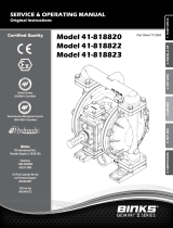
Performance
LOW PRESSURE SETTING
FLUID OUTLET PRESSURE
psi (bar, MPa)
250
(17, 1.7)
200
(13, 1.3)
150
(10, 1.0)
50
(3.4, 0.34)
0
100
(7, 0.7)
Approx. Cycles per Minute
Husky 1050HP Performance
50 100 150 200 250
AIR CONSUMPTION scfm (m
3
/min)
25
(0.7)
100
(2.8)
75
(2.1)
125
(3.5)
50
(1.4)
FLUID FLOW
(Pump tested in water with inlet submerged)
gpm
(lpm)
20
(76)
30
(114)
50
(189)
0
10
(38)
40
(151)
A
C
E
D
B
A
B
C
E
D
HIGH PRESSURE SETTING
FLUID OUTLET PRESSURE psi (bar, MPa)
125
(8.6, 0.86)
100
(7, 0.7)
75
(5.2, 0.52)
25
(1.7, 0.17)
0
50
(3.4, 0.34)
Approx. Cycles per Minute
Husky 1050HP Performance
56 112 168 224 280
AIR CONSUMPTION scfm (m
3
/min)
20
(0.6)
80
(2.3)
60
(1.7)
100
(2.8)
40
(1.1)
FLUID FLOW
(Pump tested in water with inlet submerged)
gpm
(lpm)
20
(76)
30
(114)
50
(189)
0
10
(38)
40
(151)
A
B
C
E
D
A
B
C
E
D

Call today for product information or to request a demonstration.
877.84GRACO (1-877-844-7226) or visit us at www.graco.com/process
All written and visual data contained in this document are based on the latest product information available at the time of publication. Graco reserves the right to make changes at any time without notice.
©2015 Graco Inc. Form No. 345064 Rev. B 2/15 Printed in the U.S.A.
All other brand names or marks are used for identification purposes and are trademarks of their respective owners.
Maximum fluid working pressure ..................................................................................... 250 psi (14 bar, 1.4 MPa)
Air pressure operating range ............................................................................. 20-125 psi (1.4-6.9 bar, 0.14-0.69 MPa)
Fluid displacement per cycle
Low Pressure Setting.................................................................................................0.17 gal (0.64 l)
High Pressure Setting ................................................................................................0.20 gal (0.76 l)
Air consumption at 70 psi (4.8 bar), 20 gpm (76 lpm)
Low Pressure Setting.............................................................................................26 scfm (0.7 m3/min)
High Pressure Setting ...........................................................................................51 scfm (1.4 m3/min)
Maximum values with water as media under submerged inlet conditions at ambient temperature:
Maximum air consumption
Low Pressure Setting ..........................................................................................59 scfm (1.7 m3/min)
High Pressure Setting ..........................................................................................95 scfm (2.7 m3/min)
Maximum free-flow delivery
Low Pressure Setting ............................................................................................ 50 gpm (189 lpm)
High Pressure Setting ............................................................................................ 46 gpm (174 lpm)
Maximum pump speed
Low Pressure Setting ...................................................................................................280 cpm
High Pressure Setting ...................................................................................................225 cpm
Maximum suction lift*
Dry ................................................................................................................ 16 ft (4.9 m)
Wet ............................................................................................................... 29 ft (8.8 m)
Maximum size pumpable solids ..............................................................................................1/8 in (3.2 mm)
Recommended cycle rate for continuous use .................................................................... 93–140 cpm (in Low or High setting)
Air inlet size . . . . . . . . . . . . . . . . . . . . . . . . . . . . . . . . . . . . . . . . . . . . . . . . . . . . . . . . . . . . . . . . . . . . . . . . . . . . . . . . . . . . . . . . . . . . . . . . . . . . . . . . . . . . . . . . . 3/4 npt(f)
Fluid inlet size..........................................................................................................1 in npt(f) or bspt
Fluid outlet size.........................................................................................................1 in npt(f) or bspt
Weight
Aluminum manifolds ..................................................................................................48 lb (21.8 kg)
SST manifolds.......................................................................................................60 lb (27.2 kg)
Wetted parts................................................... aluminum or stainless steel plus the material(s) chosen for seat, ball, and diaphragm options
Non-wetted external parts ....................................................................................aluminum, coated carbon steel, sst
*Varies based on ball/seat selection and wear, operating speed, material properties, and other variables
Part No. Seat Ball Fluid Diaphragm Center Diaphragm Fluid Covers Fluid Manifold Porting
24W756 Stainless Steel Santoprene Santoprene Santoprene Stainless Steel Aluminum
NPT
24W757 Stainless Steel Santoprene Santoprene Santoprene Stainless Steel Aluminum
BSPT
24W758 Stainless Steel Santoprene Santoprene Santoprene Stainless Steel Stainless Steel
NPT
24W759 Stainless Steel Santoprene Santoprene Santoprene Stainless Steel Stainless Steel
BSPT
24W762 Santoprene Santoprene Santoprene Santoprene Stainless Steel Aluminum
NPT
24W763 Santoprene Santoprene Santoprene Santoprene Stainless Steel Aluminum
BSPT
24W764 Geolast Geolast Buna Santoprene Stainless Steel Aluminum
NPT
24W765 Geolast Geolast Buna Santoprene Stainless Steel Aluminum
BSPT
24W766 Stainless Steel Weighted Neoprene Buna Santoprene Stainless Steel Aluminum
NPT
24W767 Stainless Steel Weighted Neoprene Buna Santoprene Stainless Steel Aluminum
BSPT
24W768 Stainless Steel Weighted Neoprene Neoprene Overmold Santoprene Stainless Steel Aluminum
NPT
24W769 Stainless Steel Weighted Neoprene Neoprene Overmold Santoprene Stainless Steel Aluminum
BSPT
24X388 Stainless Steel Stainless Steel 2-piece PTFE/Santoprene Santoprene Stainless Steel Stainless Steel
NPT
24X389 Stainless Steel Stainless Steel 2-piece PTFE/Santoprene Santoprene Stainless Steel Stainless Steel
BSPT
*Note: All fluid covers are stainless steel. Fluid manifolds will differ between aluminum and stainless steel.
Technical Specifications
Ordering Information
/