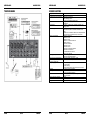
JBSYSTEMS SMP 8.2 Owner's manual
- Category
- Audio mixers
- Type
- Owner's manual
Page is loading ...

EN - DISPOSAL OF THE DEVICE
Dispose of the unit and used batteries in an environment friendly manner
according to your country regulations.
FR - DÉCLASSER L’APPAREIL
Débarrassez-vous de l’appareil et des piles usagées de manière écologique
Conformément aux dispositions légales de votre pays.
NL - VERWIJDEREN VAN HET APPARAAT
Verwijder het toestel en de gebruikte batterijen op een milieuvriendelijke
manier conform de in uw land geldende voorschriften.
DU - ENTSORGUNG DES GERÄTS
Entsorgen Sie das Gerät und die Batterien auf umweltfreundliche Art und
Weise gemäß den Vorschriften Ihres Landes.
ES - DESHACERSE DEL APARATO
Reciclar el aparato y pilas usadas de forma ecologica conforme a las
disposiciones legales de su pais.
PT - COMO DESFAZER-SE DA UNIDADE
Tente reciclar a unidade e as pilhas usadas respeitando o ambiente e em
conformidade com as normas vigentes no seu país.

ENGLISH OPERATION MANUAL
SYNQ
®
1/98 SMP8.2
OPERATION MANUAL
Thank you for buying this SYNQ
®
product. To take full advantage of all possibilities, please read these
operating instructions very carefully.
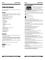
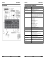
FEATURES
This unit is radio-interference suppressed. This appliance meets the requirements of the current European
and national guidelines. Conformity has been established and the relevant statements and documents have
been deposited by the manufacturer.
8 channel PA-mixing console with very low noise architecture.
Internal 24bit DSP-effect unit with 100 presets & foot switch
USB in/out for direct recording to PC
4 balanced input channels, 2 Mono & 3 Stereo channels:
Input gain
Inserts on mono channels
Peak indication @ -5dB
High pass filter @ 75Hz
3band equalizer
1 AUX send EFX send for effects section (post)
PAN/BAL control
PFL-switch
LEVEL control
48V Phantom power available on all balanced microphone inputs
Use of external effects possible
Balanced Main L/R output controls
Headphone and control room output
2x 10 section LED VU-meters
External power transformer
BEFORE USE
Before you start using this unit, please check if there’s no transportation damage. Should there be any, do
not use the device and consult your dealer first.
Important: This device left our factory in perfect condition and well packaged. It is absolutely necessary
for the user to strictly follow the safety instructions and warnings in this user manual. Any damage caused
by mishandling is not subject to warranty. The dealer will not accept responsibility for any resulting defects
or problems caused by disregarding this user manual.
Keep this booklet in a safe place for future consultation. If you sell the fixture, be sure to add this user
manual.
To protect the environment, please try to recycle the packing material as much as possible.
Check the contents:
Check that the carton contains the following items:
User manual
SMP8.2 mixer
Power supply
ENGLISH OPERATION MANUAL
SYNQ
®
2/98 SMP8.2
SAFETY INSTRUCTIONS:
To prevent fire or shock hazard, do not expose this appliance to rain or moisture.
To avoid condensation to be formed inside, allow the unit to adapt to the surrounding temperatures when
bringing it into a warm room after transport. Condense sometimes prevents the unit from working at full
performance or may even cause damages.
This unit is for indoor use only.
Don’t place metal objects or spill liquid inside the unit. No objects filled with liquids, such as vases, shall be
placed on this appliance. Electric shock or malfunction may result. If a foreign object enters the unit,
immediately disconnect the mains power.
No naked flame sources, such as lighted candles, should be placed on the appliance.
Don’t cover any ventilation openings as this may result in overheating.
Prevent use in dusty environments and clean the unit regularly.
Keep the unit away from children.
Inexperienced persons should not operate this device.
Maximum save ambient temperature is 40°C. Don’t use this unit at higher ambient temperatures.
Minimum distances around the apparatus for sufficient ventilation is 5cm.
Always unplug the unit when it is not used for a longer time or before you start servicing.
The electrical installation should be carried out by qualified personal only, according to the regulations for
electrical and mechanical safety in your country.
Check that the available voltage is not higher than the one stated on the rear panel of the unit.
The socket inlet shall remain operable for disconnection from the mains.
The power cord should always be in perfect condition. Switch the unit immediately off when the power cord
is squashed or damaged. It must be replaced by the manufacturer, its service agent or similarly qualified
persons in order to avoid a hazard.
Never let the power-cord come into contact with other cables!
In order to avoid a hazard, the unit shall only be used with the AC-adaptor delivered with it. If the AC-
adaptor is damaged, a same model adaptor shall be used only.
When the power switch is in OFF position, this unit is not completely disconnected from the mains!
This appliance must be earthed to in order comply with safety regulations.
In order to prevent electric shock, do not open the cover. Apart from the mains fuse there are no user
serviceable parts inside.
Never repair a fuse or bypass the fuse holder. Always replace a damaged fuse with a fuse of the same
type and electrical specifications!
In the event of serious operating problems, stop using the appliance and contact your dealer immediately.
Please use the original packing when the device is to be transported.
Due to safety reasons it is prohibited to make unauthorized modifications to the unit.
CAUTION
CAUTION: To reduce the risk of electric shock, do not
remove the top cover. No user-serviceable parts inside.
Refer servicing to qualified service personnel only.
The lightning flash with arrowhead symbol within the equilateral triangle is intended to alert the
use or the presence of un-insulated “dangerous voltage” within the product’s enclosure that may
be of sufficient magnitude to constitute a risk of electric shock.
The exclamation point within the equilateral triangle is intended to alert the user to the presence of
important operation and maintenance (servicing) instructions in the literature accompanying this
appliance.
This symbol means: indoor use only
This symbol means: Read instructions
This symbol means: Safety Class II appliance

ENGLISH OPERATION MANUAL
SYNQ
®
3/98 SMP8.2
INSTALLATION GUIDELINES:
Install the unit in a well-ventilated location where it will not be exposed to high temperatures or humidity.
Placing and using the unit for long periods near heat-generating sources such as amplifiers, spotlights, etc.
will affect its performance and may even damage the unit.
When installed in a booth or flight case, please make sure to have good ventilation to improve heat
evacuation of the unit.
To avoid condensation to be formed inside, allow the unit to adapt to the surrounding temperatures when
bringing it into a warm room after transport. Condense sometimes prevents the unit from working at full
performance.
CLEANING THE APPLIANCE:
Clean by wiping with a polished cloth slightly dipped with water. Avoid getting water inside the unit. Do not
use volatile liquids such as benzene or thinner which will damage the unit.
CONNECTIONS
For more information on connections, please refer to the next chapter.
Be sure to turn off the mixer before you make changes to the different connections.
In this manual we talk about “line inputs”. This is a global name for inputs with a level between 750mV and
2V. This includes tuners, videos, CD-players, etc.
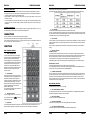
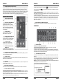
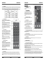
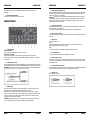
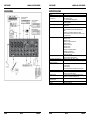
FUNCTIONS
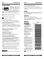
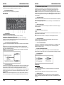
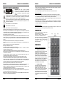
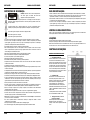
INPUT CHANNEL CONTROL
1. PEAK LED INDICATOR
This LED indicator shows the level of the signal
input of the channel. The peak indicator lights up
when the input signal reaches 5dB below the
channel’s clipping point. This indicator shows the
level of the Post-EQ/ pre-fader signal. If the PEAK
indicator lights more than briefly on high-level
transients, you should use the TRIM control to
decrease the input sensitivity of the channel. If this
does not work, reduce the output level of the
connected source.
2. TRIM CONTROL
According to the level of the input signal, use this
knob to adjust the input to an appropriate level. The
best balance of S/N and dynamic range will be
achieved if you adjust the TRIM control so that the
peak indicator lights occasionally. This control
adjusts the channel’s MIC input sensitivity between
-50dB and -6dB and the line input sensitivity
between -30dB and +14dB.
The mono/stereo combination input channels have
a sensitivity of +20dB to-20dB
3. HPF(High-Pass Filter)
This switch toggles the HPF on or off. To turn the
HPF on, press the switch In ( ). The HPF cut
frequencies below 75Hz
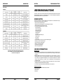
4. EQUALIZER
This 3-band equalizer adjusts the channel’s high, mid and low frequency bands. Setting the knob to the “0”
position produces a flat frequency response. Turning the knob to the right boosts the corresponding
ENGLISH OPERATION MANUAL
SYNQ
®
4/98 SMP8.2
frequency band ,while turning to the left cuts the band.
The following table shows the EQ type, frequency, and maximum cut/boost for each of the three bands.
5. AUX CONTROL
The AUX knob controls the signal level that the channel sends to the AUX bus.
If you are using stereo channels, the signals from the L and R channels are mixed and send to the AUX bus.
The AUX controls are switched as pré fader. Pré-fader aux outputs are not influenced by the position of the
channel fader and are mainly used to control stage monitors.
6. EFX CONTROL.
This knob controls the level of the signals sent to the EFX bus (to the EFX SEND jack on the front panel and
to the internal effect module). The channel signals mixed by this bus have their overall level set by the EFX
SEND Control.
Since this control is placed after the channel fader, the signal level will be affected by the channel fader’s
setting.
7. PAN /BAL CONTROL
PAN (Mono Channel)
This control pans the channel signal across the master L and R busses, thus determining the perceived
position of the sound from that channel in the output stereo sound field. If a PAN control is set all the way to
the left, for example, the sound from that channel will be heard from the left speaker system only.
If it is set all the way to the right, the sound will be heard from the right speaker system only.
Intermediate settings will cause the sound to appear at corresponding locations in the stereo sound field.
BALANCE (Stereo Channel)
This control adjusts the balance or the L/R position of the stereo input signal.
Turning the BALANCE control to the left of center moves the apparent source toward the MAIN MIX L bus,
turning it to the right moves the source toward the MAIN MIX R bus.
8. CHANNEL VOLUME KNOB
This is the channel’s main level control. It determines the level of the signal that is sent from the channel to
the master mixing effect bus. It is the settings of the input channel volume knobs that determine the mix, or
the balance of sound levels between the instruments or other sources connected to the inputs. When a
channel is not being used, its volume knob should be set at the minimum position to prevent the addition of
unwanted noise to the main program signal.
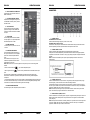
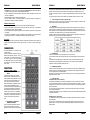
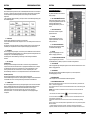
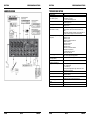
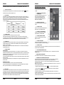
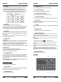
MAIN CONTROL SECTION
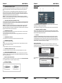
1. DSP PROGRAM DISPLAY
The selected DSP effect number is shown on the display.
2. DSP PROGRAM SELECT SWITCH
Turn the program knob to select one of the 100 built-in digital effects. The 24 Bit Digital Effects processor
provides high quality effects like Delay, Chorus and Reverb.
3. DSP ON/OFF SWITCH
This switch turns the internal digital effect on/off.
4. EFX RTN VOLUME KNOB
Adjust the level of the signal sent from the internal digital effect to the MAIN bus.
5. CTRL ROOM /PHONES CONTROL
Controls the signal output level of the PHONES and CONTROL ROOM outputs.

ENGLISH OPERATION MANUAL
SYNQ
®
5/98 SMP8.2
6. MAIN L/R MASTER VOLUME KNOB
Adjusts the final output level that is sent to the
MAIN L/R OUTPUTS.
7. AUX STEREO RETURN CONTROL
Adjusts the level of the signal coming from the
AUX RETURN connectors (L and R), routed to
the MAIN L/R bus.
8. TAPE IN CONTROL
This knob controls the level of the playback
signal that is coming from the TAPE IN RCA
connectors, and that will be routed to the MAIN
L/R output.
9. LEVEL METER
This LED display shows the level of the MAIN
L/R output signal. The “0” point corresponds to
the standard output level of +4dB.
10. POWER INDICATOR
This indicator lights when power switch of the mixer
is turned on.
11. PHANTOM POWER SWITCH
This switch toggles the phantom power on or
off. If you set the switch on, the mixer supplies
power to all channels that provide XLR MIC
inputs.
Set this switch on when using one or more
condenser microphones that need to receive
external power from the mixer.
NOTE
: When this switch is on, the mixer supplies DC +48V power to pins 2 and 3 of all XLR-type MIC
INPUTS.
* Be sure to leave this switch off ( ) if you do not need phantom power.
* When tuning the switch on ( ), be sure that only condenser MICs are connected to the XLR input
jacks.
Devices other than condenser MICs may be damaged if connected to the phantom power supply.
Note, however, that the switch may be left on without problem when connecting to balanced dynamic
microphones.
* To avoid damage to speakers, be sure to turn off amplifier (on powered speakers) before turning this switch
on or off. We also recommend that you turn all out controls to minimum settings before operating the switch,
to avoid risk of loud noises that could cause hearing loss or device damage.
12. PHANTOM POWER INDICATOR
This indicator lights up when the phantom power is switched on.
ENGLISH OPERATION MANUAL
SYNQ
®
6/98 SMP8.2
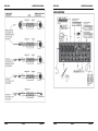
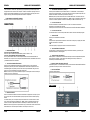
CONNECTORS
1. CHANNEL INPUTS
BALANCED MIC XLR Connectors
These are balanced XLR-type input jacks (1: Sleeve, 2: Hot, 3:Cold)
BALANCED LINE IN JACK Connectors
A standard 1/4” TRS phone jack is used for balanced or unbalanced line level signals, like used with most
electronic keyboards, synthesizers, tape decks and the line outputs from other mixers.
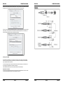
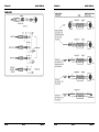
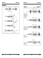
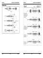
2. CHANNEL INSERT I/O JACK
These are input/output jacks located between the head-amplifier and the high pass filter.
These jacks can be used to independently connect these channels to devices such as graphic equalizers,
compressors, and noise filters. These are 1/4” TRS (tip, ring, sleeve) phone jacks that support bi-directional
operation.
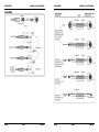
NOTE:
Connection to an INSERT I/O jack requires a special separately-sold insertion cable such as
illustrated below.
3. CHANNEL INPUT JACKS
These are unbalanced stereo line input connectors. Two types are provided: Jack type and RCA pin type.
For stereo signals, you need of course to connect both Left and Right channels.
Channels CH9/10 and CH11/12 can also be used for mono signals. If you need to connect a mono signal,
then use only the L MONO Jack input. When the mixer detects no connector in the R input, it will spread the
signal of the L MONO Jack input over both L and R channels.
NOTE:
Channels 7/8 provide 2 types of inputs: jack and RCA connectors. Please use only one of these
inputs. Never use both input types at the same time on the same channel.
4. STEREO RETURN L (MONO), R JACK
These are unbalanced 1/4” TRS phone-type line input jacks. The signal received by these jacks is sent to the
MAIN bus and AUX buss. These jacks are mainly used to receive a return signal from an external effect
(reverb, delay, etc.)
NOTE: These jacks can also be used as an auxiliary stereo input. If you need to connect a mono signal, then
use only the L MONO Jack input. When the mixer detects no connector in the R input, it will spread the
signal of the L MONO Jack input over both L and R channels.

ENGLISH OPERATION MANUAL
SYNQ
®
7/98 SMP8.2
5. TAPE IN RCA connectors
Use these RCA connectors when you want to connect a CD, DAT or other external sound source directly to
the mixer for monitoring.
You can adjust the signal level using the TAPE/USB control in the MAIN CONTROL SECTION.
6. REC OUT RCA connectors
The REC OUT connectors send the pre-fader signal from the master bus. U can use this output for
recording.
7. SEND JACKS
These are unbalanced phone jacks
* AUX
These jacks output sends the signal form AUX bus. You can use this jack, for example to connect powered
stage monitors.
* EFX
You can use this jack for example to connect an external effect unit.
8. FOOT SWITCH JACK
A foot switch can be connected to this phone input jack and can be used to turn the digital effects ON/OFF.
9. MAIN L/R OUTPUT JACKS
Balanced 1/4” Jack outputs. You can use these outputs to connect the power amplifiers for you main
speakers, or you can use them when you wish to record the signal that is also influenced by the main output
faders.
10. CONTROL ROOM OUTPUT JACKS
These unbalanced 1/4” Jack outputs are controlled by the CTRL ROOM /PHONES CONTROL and are
generally used to connect a monitoring system.
11. PHONES JACK
Stereo headphones connector.
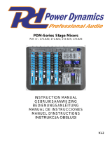
REAR PANEL
1. POWER SUPPLY CONNECTOR
Connect the included power supply here. Replace this power supply only with exactly the same type number.
Use of a different adaptor may result in fire or electric shock.
2. POWER SWITCH
Used to switch the mixer on/off. We strongly advise to set the master output faders of the mixer and the gain
controls of your amplifier to zero before you switch the mixer on or off
ENGLISH OPERATION MANUAL
SYNQ
®
8/98 SMP8.2
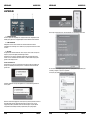
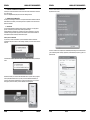
3. USB PORT
The built-in stereo USB audio interface allows you to connect your mixer to a PC for recording or playback.
Virtually any digital recording software can be used.
The PC/Mac will detect your mixer as a sound card, so normally no drivers are needed. This means also you
will be able to use the standard audio interface controls in the MAC or Windows operating system to make all
the settings.
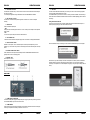
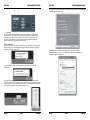
Getting Started with Windows XP
The first time you plug the mixer into a USB port, Windows will install the universal drivers for that port. A
balloon tip will pop up, telling you it has found the USB Audio codec.
When the installation is ready, the message “Your new hardware is installed and ready to use” will appear
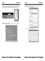
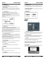
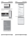
Most of the time, you’ll want the output volume from the computer at it’s maximum position, but sometimes
the default setting is much lower, what makes the output level too low. The volume can be increased in
several ways. The simplest is to click the loudspeaker icon (figure 3) in the system tray and drag the slider to
the top

ENGLISH OPERATION MANUAL
SYNQ
®
9/98 SMP8.2
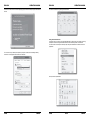
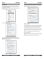
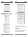
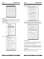
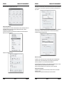
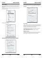
If the icon is not there, the volume can be changed by going to Control Panel and opening Sounds and Audio
Devices.
To use the mixer as your default input/output device (for system sounds and audio recording software),
ensure that it is set for playback and recording in the Audio tab.
ENGLISH OPERATION MANUAL
SYNQ
®
10/98 SMP8.2
The volume can then be set by pressing the Volume button
Getting Started with MAC OS X
Connect the mixer to your mac by using a standard USB cable. The LED will light up to indicate it is receiving
USB power. The MAC will recognize the USB audio device and automatically install a universal driver.
To select the mixer as the computer’s audio input, open the System Preferences from the dock or the main
Apple Menu.
Next: open the Sound preferences.

ENGLISH OPERATION MANUAL
SYNQ
®
11/98 SMP8.2
Now, click on the Input tab and select USB Audio Codec. You may notice that the Volume slider sets itself to
the highest level. This will allow you to use the level controls of the mixer at their full range.
Then click on the Output tab and select USB Audio Codec. You may notice that the Volume slider sets itself
to the full level. You may notice that the Volume slider sets itself to the highest level. This will allow you to
use the level MAIN controls of the mixer to set the exact output level.
Recording to the USB I/O
For recording a live performance, you can send the main output mix to a computer by using the USBI/O
connector. The output signal will only be influenced by the individual channel settings and channel faders,
not by the MAIN L/R master output fader.
You can also assign the outputs of the AUX1 and AUX2 to the USB out, enabling you to build a stereo mix
for recording that’s independent from the house sound system.
Press the USB SEND switch down to send the AUX1 and AUX2 mix to the USB input.
Playback from the USB I/O
For playback, the USB stereo signal goes directly via the TAPE IN to the MAIN OUTPUT mix of the console.
You can set the USB playback level by using the TAPE/USB volume knob.
ENGLISH OPERATION MANUAL
SYNQ
®
12/98 SMP8.2
WIRING
Page is loading ...

ENGLISH OPERATION MANUAL
SYNQ
®
15/98 SMP8.2
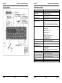
SPECIFICATIONS
Power Supply AC 230 V, 50Hz
Power consumption 25W
Max output level (0.5% thd @ 1kHz) +26dB (MAIN L/R)
+20dB (INSERT)
More than 100mW (HEADPHONES) @33Ohm
T.H.D. <0.1% @ +14dB 20Hz~20kHz (MIX L/R, AUX SEND, EFX SEND,
CTRL ROOM)
Frequency response 20Hz~20kHz, +1/-2dB (MIX L/R, AUX SEND, EFX SEND, CTRL
ROOM)
Hum and Noise (average Rs=150Ohm) -127dB equivalent input noise
-95dB residual noise (MIX L/R, AUX SEND, EFX SEND, CTRL
ROOM)
-88dB (MIX L/R, AUX SEND, EFX SEND, CTRL ROOM) Master fader
at nominal level and all channel volumes at minimum.
Maximum Voltage Gain 66dB MIC IN TO MAIN L/R
60dB MIC IN TO AUX
66dB MIC IN TO EFX
76dB MIC IN TO CONTROL ROOM L/R
58.2dB IN TO REC L/R
46dB LINE IN TO MAIN L/R
46dB LINE IN TO AUX
46dB LINE IN TO EFX
56dB LINE IN TO CONTROL ROOM L/R
36dB STEREO IN TO MAIN L/R
6dB AUX RETURN IN TO MAIN L/R
16dB TAPE IN TO MAIN L/R
Crosstalk (@ 1kHz) -70dB between input channels
-70dB between input/oputput channels
Gain Control (mono input channel) 44dB Variable (-50dB ~ -6dB) (-30dB ~ +14dB)
Gain Control
(combined mono/stereo input channel)
40dB Variable (-20dB ~ +20dB)
Input channel Equalization HIGH: 12kHz shelving
MID: 2.5kHz peaking
LOW: 80Hz shelving
*Turnover/roll off frequencies: located 3dB below max. boost/cut
LED Meters 2x 10 segment LED for MAIN L/R
Internal Digital Effect 100 selectable presets
FOOT Switch control (ON/OFF)
Channel indicators Peak: an indicator for each channel turns on when the pré-channel
fader signal is 5dB below clipping
Phantom Power (balanced input) +48V DC
Weight 2,8 kg
Dimensions 249(W) x 75(H) x 295(D) mm
ENGLISH OPERATION MANUAL
SYNQ
®
16/98 SMP8.2
Specifications
-INPUT
-OUTPUT
Every information is subject to change without prior notice
You can download the latest version of this user manual on our website: www.beglec.com
Page is loading ...
Page is loading ...
Page is loading ...
Page is loading ...
Page is loading ...
Page is loading ...
Page is loading ...
Page is loading ...
Page is loading ...
Page is loading ...
Page is loading ...
Page is loading ...
Page is loading ...
Page is loading ...
Page is loading ...
Page is loading ...
Page is loading ...
Page is loading ...
Page is loading ...
Page is loading ...
Page is loading ...
Page is loading ...
Page is loading ...
Page is loading ...
Page is loading ...
Page is loading ...
Page is loading ...
Page is loading ...
Page is loading ...
Page is loading ...

ESPAÑOL MANUAL DE FUNCIONAMIENTO
SYNQ
®
77/98 SMP8.2
CONEXIONES
ESPAÑOL MANUAL DE FUNCIONAMIENTO
SYNQ
®
78/98 SMP8.2
Page is loading ...
Page is loading ...
Page is loading ...
Page is loading ...
Page is loading ...
Page is loading ...
Page is loading ...
Page is loading ...
Page is loading ...
Page is loading ...
-
 1
1
-
 2
2
-
 3
3
-
 4
4
-
 5
5
-
 6
6
-
 7
7
-
 8
8
-
 9
9
-
 10
10
-
 11
11
-
 12
12
-
 13
13
-
 14
14
-
 15
15
-
 16
16
-
 17
17
-
 18
18
-
 19
19
-
 20
20
-
 21
21
-
 22
22
-
 23
23
-
 24
24
-
 25
25
-
 26
26
-
 27
27
-
 28
28
-
 29
29
-
 30
30
-
 31
31
-
 32
32
-
 33
33
-
 34
34
-
 35
35
-
 36
36
-
 37
37
-
 38
38
-
 39
39
-
 40
40
-
 41
41
-
 42
42
-
 43
43
-
 44
44
-
 45
45
-
 46
46
-
 47
47
-
 48
48
-
 49
49
-
 50
50
-
 51
51


JBSYSTEMS SMP 8.2 Owner's manual
- Category
- Audio mixers
- Type
- Owner's manual
Ask a question and I''ll find the answer in the document
Finding information in a document is now easier with AI
in other languages
- français: JBSYSTEMS SMP 8.2 Le manuel du propriétaire
- español: JBSYSTEMS SMP 8.2 El manual del propietario
- Deutsch: JBSYSTEMS SMP 8.2 Bedienungsanleitung
- Nederlands: JBSYSTEMS SMP 8.2 de handleiding
- português: JBSYSTEMS SMP 8.2 Manual do proprietário
Related papers
-
JBSYSTEMS LIGHT SMP 12.22 Owner's manual
-
-
-
JBSYSTEMS LIGHT MM-10 Owner's manual
-
-
JBSYSTEMS LIGHT CDX.2 Owner's manual
-
-
 JBSYSTEMS MPL 1 BASE Owner's manual
-
-
JBSYSTEMS LIGHT DLP-6 Owner's manual

Other documents
-
 Power Dynamics PDM Series PDM-S804A 8-Channel MP3 DSP USB Bluetooth Mixer Owner's manual
-
TRONIOS PDM-Series User manual
-
Vonyx STM3025 Owner's manual
-
Power Dynamics PDM-Series User manual
-
Power Dynamics PDM-S1204 Owner's manual
-
 Power Dynamics 172.624 User manual
-
-
Vonyx VMM-K Series Music Mixer User manual
-
 Power Dynamics 10031794 Owner's manual
-
Vonyx STM-7010 Owner's manual


