Page is loading ...

MSAsafety.com
User Instructions/Instrucciones de uso/Mode d'emploi
Beam Trolley
Order No./N. º de pedido/Nº de commande : 10176476/00
Print Spec/Especif. impr./Spéc. d'imp. : 10000005389 (R)

WARNING
National standards and state, provincial and federal laws require the user to be trained before using
this product. Use this manual as part of a user safety training program that is appropriate for the
user’s occupation. These instructions must be provided to users before use of the product and
retained for ready reference by the user. The user must read, understand (or have explained), and
heed all instructions, labels, markings and warnings supplied with this product and with those prod-
ucts intended for use in association with it. FAILURE TO DO SO MAY RESULT IN SERIOUS INJURY
OR DEATH.
1000 Cranberry Woods Drive
Cranberry Township, PA 16066
USA
Phone 1-800-MSA-2222
Fax 1-800-967-0398
For your local MSA contacts please go to our website www.MSAsafety.com
©
MSA 2016. All rights reserved/Todos los derechos reservados/Tous droits réservés
¡Aviso!
Las normativas nacionales, al igual que las leyes estatales, provinciales y federales establecen que
el usuario reciba capacitación pertinente antes del uso de este producto. Utilice este manual como
parte del programa de capacitación de seguridad específico para el cargo del usuario. Estas instruc-
ciones deberán suministrarse al usuario quien deberá leerlas antes del uso del producto y conser-
varlas para futuras consultas. El usuario debe leer, comprender (o hacerse explicar) y respetar todas
las instrucciones, las etiquetas, los marcados y las advertencias que trae el producto. DE LO CON-
TRARIO PUEDEN PROVOCARSE LESIONES GRAVES O INCLUSO LA MUERTE.
Attention !
Les normes nationales, ainsi que les lois fédérales et provinciales exigent que l’utilisateur reçoive la
formation nécessaire avant d’utiliser ce produit. Utiliser ce manuel dans le cadre d’un programme de
formation sur la sécurité correspondant à la profession de l’utilisateur. Ces directives doivent être
fournies aux utilisateurs avant qu’ils ne commencent à utiliser le produit, et laissées à leur disposition
pour consultation future. L’utilisateur doit lire, comprendre (ou se faire expliquer) les directives, les
étiquettes, les notices et les avertissements relatifs à ce produit et aux produits associés; il doit bien
les comprendre et s’y conformer. LE NON-RESPECT DE CES DIRECTIVES PEUT CAUSER DES
BLESSURES GRAVES OU MÊME LA MORT!

3
Contents
Beam Trolley
US
Contents
1 Safety Regulations .................................................................................................................... 4
1.1 Correct Use ....................................................................................................................................... 4
1.2 Usage Specifications ......................................................................................................................... 4
1.3 Use Instructions ................................................................................................................................. 5
1.4 Usage Limitations .............................................................................................................................. 5
1.4.1 Physical Limitations ........................................................................................................................... 5
1.4.2 Design Limitations ............................................................................................................................. 5
1.4.3 Compatibility of Components and Subsystems ................................................................................. 6
1.4.4 Compatibility of Connectors .............................................................................................................. 6
1.5 Liability Information ........................................................................................................................... 6
1.6 Safety and Precautionary Measures to be Adopted .......................................................................... 7
1.7 Warranty ............................................................................................................................................ 7
2 Description ................................................................................................................................. 8
2.1 Loading Conditions ............................................................................................................................ 8
2.2 Markings and Labels ......................................................................................................................... 8
3 Use .............................................................................................................................................. 9
3.1 Planning the Use of Systems ............................................................................................................ 9
3.1.1 Free Fall Distance, Total Fall Distance and System Elongation ....................................................... 9
3.1.2 Pendulum (Swing) Falls .................................................................................................................... 9
3.1.3 Rescue and Evacuation .................................................................................................................... 9
3.2 Installation Instructions .................................................................................................................... 10
4 Cleaning, Maintenance and Storage ...................................................................................... 10
5 Inspection ................................................................................................................................. 10
5.1 Inspection Frequency ...................................................................................................................... 10
5.2 Procedure for Inspection before each Use ...................................................................................... 10
5.3 Procedure for Formal Inspection ..................................................................................................... 11
5.4 Inspection Log ................................................................................................................................. 11
5.5 Inspection Diagram ......................................................................................................................... 11

4
Safety Regulations
Beam Trolley
US
1 Safety Regulations
1.1 Correct Use
The Beam Trolley is an anchorage connector designed to function as an interface between an anchorage
beam and a fall protection, work positioning, rope access, or rescue system for the purpose of coupling the
system to the anchorage.
It is imperative that this manual must be read and observed when using the device. In particular, the safety
instructions, as well as the information for the use and operation of the device, must be carefully read and
observed. Furthermore, the national regulations applicable in the user's country must be taken into account
for a safe use.
Alternative use, or use outside this specification will be considered as non-compliance. This also applies
especially to unauthorized alterations to the device and to commissioning work that has not been carried
out by MSA or authorized persons.
1.2 Usage Specifications
- The Beam Trolley meets ANSI Z359.1-2007 and OSHA 1910 Appendix C.
- Maximum Capacity: One worker with maximum weight of 400 lbs (181 kg) including the weight of the
user plus clothing, tools and other user-borne objects. For ANSI Z359.1 applications, maximum capacity
is 310 lbs (140 kg).
- Maximum Static Load Rating: 5,000 lbf (22.2 kN)
- Weight: 7.7 lbs (3.5 kg)
- Beam Flange Width Range: 3“-10“ (76 - 254 mm)
- Beam Flange Thickness: 1/4“ to 7/8“ (6 - 22 mm)
- Component Materials:
Cross bar and Rollers: Aluminum
Webbing: Polyester
Swivel Ring: Zinc Plated Steel
Spring and Hardware: Stainless Steel
- When used as part of a personal fall arrest system, fall arrest forces must not exceed 1,800 lbf (8 kN).
- Free fall distance (limit) must not exceed 6.0 ft (1.8 m) in accordance with ANSI Z359.1. The Canadian
Occupational Health & Safety Act of 1990 specifies that the free fall distance must not exceed 5 ft
(1.5 m). The user must comply with applicable standards.
NOTE: When it is infeasible to limit free fall distance to 6 ft (1.8 m) or less, U.S. Federal OSHA has provided
for exemption from this rule. In an interpretation of 29 CFR 1926.502 (d)(16) dated December 4, 1996,
OSHA issued the ruling that personal fall arrest systems may be used in applications where the free fall
distance may exceed 6 ft (1.8 m), provided the employer can document that the arresting force limits are
maintained and the assembled system will operate properly. MSA 12 ft Free Fall Lanyards meet the require-
ments of this ruling, when used as part of a compatible personal fall arrest system that includes a qualified
anchorage and a full body harness. See product label for specific permissible free fall distance. MSA recom-
mends that users consult national, state, and local regulations for their specific industry application to be
assured of compliance.

5
Safety Regulations
Beam Trolley
US
1.3 Use Instructions
- A user must be of sound mind and body to properly and safely use this equipment in normal and emer-
gency situations. Users must have a physician ensure they are clear of any medical conditions that may
affect the proper and safe use of this equipment in normal and emergency situations.
- Before using a personal fall arrest system, user must be trained in accordance with the requirements of
OSHA 29 CFR 1910.66 in the safe use of the system and its components.
- Use only with ANSI, OSHA or CSA compliant personal fall arrest or restraint systems. The anchorage
beam and supporting structure must have the strength of supporting a static load, applied in the direc-
tions permitted by the system and this manual, of at least 5,000 lbf (22 kN) for each trolley on the beam.
This load rating can be reduced to 3,600 lbf (16 kN) only if the personal fall arrest system is certified by
a qualified person. Consult ANSI Z359.6 and/or CSA Z259.16 for additional information on certified
anchorages.
- The user shall be equipped with a means of limiting the maximum dynamic forces exerted on the user
during the arrest of a fall to a maximum of 8 kN (1,800 lbf).
- Use of this product must be approved by an engineer or other qualified person to be compatible with any
and all structural & operational characteristics of the selected installation location and system to be
connected to this anchorage connector.
- The Beam Trolley must be inspected prior to each use for wear, damage, and other deterioration, and
formally inspected at least semi-annually. See section 5 for specific inspection details. If such conditions
are found, remove the anchor from service immediately.
- The Beam Trolley should be positioned in such a way that minimizes the potential for falls and the poten-
tial fall distance during use. The complete fall protection system must be planned (including all compo-
nents, calculating fall clearance, and swing fall) before using.
- A rescue plan, and the means at hand to implement it, must be in place that provides the prompt rescue
of users in the event of a fall, or assures that users are able to rescue themselves.
- After a fall occurs, the anchorage connector must be removed from service immediately and destroyed.
1.4 Usage Limitations
The Beam Trolley shall not be used outside its limitations, or for any purpose other than that for which it is
intended.
1.4.1 Physical Limitations
Persons with muscular, skeletal, or other physical disorders should consult a physician before using. Preg-
nant women and minors must never use the Beam Trolley. Increasing age and lowered physical fitness may
reduce a person‘s ability to withstand shock loads during fall arrest or prolonged suspension. Consult a
physician if there is any question about physical ability to safely use this product to arrest a fall or suspend.
1.4.2 Design Limitations
- The Beam Trolley is designed for single user, with a maximum weight of 400 lbs (181 kg) including the
weight of the user plus clothing, tools, and other user-borne objects. For ANSI Z359.1 applications
maximum capacity is 310 lbs (140 kg).
- The Beam Trolley may only be loaded as shown in the LOADING CONDITIONS DIAGRAM.
- The Beam Trolley is designed to be used in temperatures ranging from -40ºF to +130ºF
(-40°C to +54°C).
- Do not expose the Beam Trolley to chemicals or harsh solutions which may have a harmful effect.
- Do not alter or modify this product in any way.
- Caution must be taken when using any component of a fall protection, work positioning, rope access, or
rescue system near moving machinery, electrical hazards, sharp edges, or abrasive surfaces, as contact
may cause equipment failure, personal injury, or death.
- Do not use/install equipment without proper training by a “competent person” as defined by
OSHA 29 CFR 1926.32(f).

6
Safety Regulations
Beam Trolley
US
- Do not remove the labeling from this product.
- Additional requirements and limitations may apply depending on anchorage type and fastening option
utilized for installation. All placements must be approved by an engineer or other qualified person.
- Do not use the Beam Trolley as part of a horizontal lifeline system.
- Use the Beam Trolley only for personal fall protection and not for lifting equipment.
1.4.3 Compatibility of Components and Subsystems
The Beam Trolley is designed to be used with MSA fall protection components and connecting subsystems.
MSA fall protection equipment has been evaluated and tested in accordance with applicable standards to
be compatible when combined in ways stipulated in MSA product user instructions.
Combining fall protection components and connecting subsystems made by different manufacturers may
adversely affect the functional compatibility between system parts and the safety and reliability of the
complete system.
It is the responsibility of the employer’s designated competent person to determine the compatibility of fall
protection components and subsystems. MSA recommends if choosing to combine fall protection compo-
nents and connecting subsystems from different manufacturers, all components and connecting subsys-
tems should be approved to comply with the applicable ANSI, CSA, or EN standard(s).
1.4.4 Compatibility of Connectors
Connectors such as D-rings, snaphooks, and carabiners must be rated to 5000 lbf (22 kN) minimum
breaking strength. Per ANSI Z359.12 and CSA Z259.12, connector gates must be able to withstand a load
of 3,600 lbf (16kN). Connecting hardware must be compatible in size and shape as to not inadvertently
cause their gate mechanisms to open.
Non-compatible connectors may accidentally disengage. Always verify compatibility of the connecting
snaphook or carabiner with harness D-ring or anchorage connector. Use only self-closing, self-locking
snaphooks and carabiners with the harness.
When using a snaphook to connect to an anchorage or when coupling components of the system together,
be certain accidental disengagement (rollout) cannot occur. Rollout is possible when interference between
a snaphook and the mating connector causes the snaphook’s gate or keeper to accidentally open and
release. Rollout occurs when a snaphook is snapped into an undersized ring such as an eye bolt or other
non-compatibly shaped connector.
Do not use snaphooks or connectors that will not completely close over the attachment object. Do not make
knots in a lanyard. Do not hook the lanyard back onto itself. Snaphooks and carabiners must not be
connected to each other. Do not attach two snaphooks into one D-ring. Always follow the manufacturer’s
instructions supplied with each system component.
1.5 Liability Information
MSA accepts no liability in cases where the product has been used inappropriately or not as intended. The
selection and use of this product must be under the direction of a qualified safety professional who has care-
fully evaluated the specific hazards of the job site where it will be used and who is completely familiar with
the product and its limitations. The selection and use of this product and its incorporation into the safety
scheme of the job site is the exclusive responsibility of the employer.
Product liability claims, warranties also as guarantees made by MSA with respect to the product are voided,
if it is not used, serviced or maintained in accordance with the instructions in this manual.
WARNING
Do not rely on feel or sound to verify proper snaphook engagement. Always check visually for proper
engagement. Ensure that gate and keeper are closed before use. Failure to follow this warning may
result in death or serious injury.

7
Safety Regulations
Beam Trolley
US
1.6 Safety and Precautionary Measures to be Adopted
It is the responsibility of the purchaser of the Beam Trolley to assure that product users are made familiar
with these User Instructions and trained by a competent person. Training must be conducted without undue
exposure of the trainee to hazards. MSA offers training programs. Contact MSA for training information.
1.7 Warranty
Express Warranty – MSA warrants that the product furnished is free from mechanical defects or faulty
workmanship for a period of one (1) year from first use or eighteen (18) months from date of shipment,
whichever occurs first, provided it is maintained and used in accordance with MSA’s instructions and/or
recommendations. Replacement parts and repairs are warranted for ninety (90) days from the date of
repair of the product or sale of the replacement part, whichever occurs first. MSA shall be released from
all obligations under this warranty in the event repairs or modifications are made by persons other than its
own authorized service personnel or if the warranty claim results from misuse of the product. No agent,
employee or representative of MSA may bind MSA to any affirmation, representation or modification of the
warranty concerning the goods sold under this contract. MSA makes no warranty concerning components
or accessories not manufactured by MSA, but will pass on to the Purchaser all warranties of manufac-
turers of such components. THIS WARRANTY IS IN LIEU OF ALL OTHER WARRANTIES, EXPRESS,
IMPLIED OR STATUTORY, AND IS STRICTLY LIMITED TO THE TERMS HEREOF. MSA SPECIFI-
CALLY DISCLAIMS ANY WARRANTY OF MERCHANTABILITY OR FITNESS FOR A PARTICULAR
PURPOSE.
Exclusive Remedy - It is expressly agreed that the Purchaser’s sole and exclusive remedy for breach of
the above warranty, for any tortious conduct of MSA, or for any other cause of action, shall be the repair
and/or replacement, at MSA’s option, of any equipment or parts thereof, that after examination by MSA
are proven to be defective. Replacement equipment and/or parts will be provided at no cost to the
Purchaser, F.O.B. Purchaser’s named place of destination. Failure of MSA to successfully repair any
nonconforming product shall not cause the remedy established hereby to fail of its essential purpose.
Exclusion of Consequential Damages - Purchaser specifically understands and agrees that under no
circumstances will MSA be liable to Purchaser for economic, special, incidental, or consequential
damages or losses of any kind whatsoever, including but not limited to, loss of anticipated profits and any
other loss caused by reason of the non-operation of the goods. This exclusion is applicable to claims for
breach of warranty, tortious conduct or any other cause of action against MSA.
For additional information please contact the Customer Service Department at 1-800-MSA-2222
(1-800-672-2222).

8
Description
Beam Trolley
US
2 Description
The Beam Trolley is an anchorage connector designed to function as an interface between an anchorage
beam and a fall protection, work positioning, rope access, or rescue system for the purpose of coupling the
system to the anchorage.
The Beam Trolley consists of a carriage with four (4) rollers containing anti-friction bearings which are rigidly
connected to aluminum housings. The housings are connected to a notched aluminum cross bar through
spring-loaded toggle plates, allowing the housings to be adjusted along the crossbar to attach to variously
sized beams. The cross bar includes a polyester webbing which connects to a steel swivel ring, which
provides a connection point for the user's personal fall arrest system. See section 5.5 for a diagram of the
Beam Trolley components.
When correctly installed on an appropriately-sized and designed beam, the Beam Trolley provides a move-
able anchorage point to allow a user to perform work at any point along the beam.
2.1 Loading Conditions
See loading conditions diagram below.
Fig. 1 Loading Conditions Diagram
2.2 Markings and Labels
The following labels must be present, legible and securely attached to the Beam Trolley.

9
Use
Beam Trolley
US
3 Use
3.1 Planning the Use of Systems
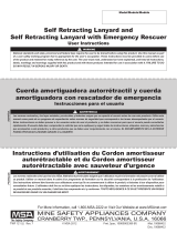
3.1.1 Free Fall Distance, Total Fall Distance and System Elongation
- Free fall distance. Limited to 6 ft (1.8 m) by OSHA and ANSI Z359.1. Limited to 5 ft (1.5 m) by Canadian
regulations.
- Total fall distance. The sum of the free fall distance and deceleration distance plus a 3 ft safety margin.
- Deceleration distance. Must not exceed 3.5 ft (1.1 m). See diagram below.
Fig. 2 Free Fall Diagram
3.1.2 Pendulum (Swing) Falls
Swing fall hazards must be minimized by anchoring directly above the user’s work space. The force of
striking an object in a pendular motion can cause serious injury. Always minimize swing falls by working as
directly below the anchorage point as possible.
3.1.3 Rescue and Evacuation
The user must have a rescue plan and the means at hand to implement it. The plan must take into account
the equipment and special training necessary to effect prompt rescue under all foreseeable conditions.
WARNING
Use of this device must be approved by an engineer or other qualified person to be compatible to
any and all structural and operational characteristics of the selected installation location and system
to be connected to this anchorage connector.
A = Free Fall
B = Deceleration Distance
AB = Total Fall Distance
C = User Height
D = 3 ft (0.9 m) Safety Margin
E = Minimum Clearance Required

10
Cleaning, Maintenance and Storage
Beam Trolley
US
3.2 Installation Instructions
Refer to the corresponding illustrations on page 30.
(1) Locate a structural steel beam flange with a width of 3" - 10" (76 mm - 254 mm) and thickness of
1/4" - 7/8" (6 mm - 22 mm) capable of withstanding a 5,000 lbf static load in the absence of certifica-
tion or 3,600 lbf static load where certification exists. For multiple personal fall arrest systems, this
static load must be multiplied by the number of trolleys on the beam.
(2) Loosen the threaded secondary safety locks on each toggle plate, then push up on the toggle plate to
allow the adjustable rollers to slide along the notched cross bar.
(3) Keeping the unit perpendicular to the beam, fit the rollers over the edges of the beam flange.
(4) Slide the adjustable rollers so that both sets of rollers are fully resting on the beam flange. The flanges
of the rollers should ride along the outside of the beam, not on it.
(5) Release the toggle plate and pull back on the adjustable rollers to ensure the ratchet teeth are fully
seated in the nearest ratchet notches.
(6) Tug, rock, and twist the anchorage connector in all directions to ensure that it cannot come off of the
flange.
(7) Screw tight the secondary safety locking screws on the bottom of the toggle plate to insure the rollers
cannot move off the edge of the flange.
(8) The rollers must ride on a clear clean surface. Remove any dirt and grit if necessary.
(9) Ensure that the Beam Trolley cannot slide off the end of the beam it is attached to. Weld or bolt in stop-
pers if necessary.
* Always re-adjust according to steps 1-9 above when moving to a new or different beam size.
4 Cleaning, Maintenance and Storage
Cleaning periodically will prolong the life and proper functioning of the product. The frequency of cleaning
should be determined by inspection and by severity of the environment. Clean with compressed air and/or
a stiff brush using plain water or a mild soap and water solution. Do not use any corrosive chemicals that
could damage the product. Wipe all surfaces with a clean dry cloth and hang to dry, or use compressed air.
When not in use, store anchorage connectors in a cool, dry, clean environment, out of direct sunlight and
free of corrosive or other degrading elements.
5 Inspection
5.1 Inspection Frequency
The Beam Trolley must be inspected by the user before each use. Additionally, it must be inspected by a
competent person other than the user at intervals of no more than six months. The competent person
inspection is referred to as Formal Inspection. See sections 5.2 and 5.3 for inspection procedures and
section 5.5 for inspection locations.
5.2 Procedure for Inspection before each Use
Perform the following steps in sequence. If in doubt about any inspection point, consult MSA or a competent
person authorized to perform Formal Inspection as described in section 5.3.
WARNING
If the Beam Trolley has been subjected to fall arrest or impact forces, it must be immediately
removed from service and marked as "UNUSABLE" and returned to MSA, or a person authorized in
writing by MSA, for inspection and repair.

11
Inspection
Beam Trolley
US
(1) Inspect the Beam Trolley labels to verify that they are present and legible. See section 2.2 for the
specific labels that should be present and the information contained thereon. Check the
Formal Inspection Log to be sure a Formal Inspection has been performed within the last six months.
If the Log does not indicate that a Formal Inspection has been performed within the last six months, or
if any labels are missing or illegible, remove the device from use and mark it as "UNUSABLE" until a
Formal Inspection is performed by a competent person.
(2) Arrange the Beam Trolley so that the parts to be inspected are readily visible. Perform a visual inspec-
tion of the trolley wheels, crossbar, swivel ring, webbing, and toggle plates.
(3) Verify that the unit can adjust and lock properly on the beam flange.
(4) Verify that the trolley wheels are engaged on the flange of the I-beam and that the trolley travels
smoothly across the beam.
5.3 Procedure for Formal Inspection
The Formal Inspection Procedure is similar to the user's inspection before each use described in
section 5.2. However, it should be performed by a competent person other than the user who is trained and
authorized to perform the Formal Inspection. The Formal Inspection should be documented and a copy of
the inspection log retained for future reference. An example inspection form is provided in section 5.4.
5.4 Inspection Log
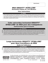
5.5 Inspection Diagram
Refer to page 31.
WARNING
If any damage that could affect the strength or operation or unsafe conditions are found, the
anchorage connector must be rendered unusable and then disposed of properly. If there is any ques-
tion as to reliability or suitability for service, contact MSA.
Model No.: Inspector:
Serial No.: Inspection Date:
Date Made: Disposition:
Comments:

30
Beam Trolley
Installation Instructions/Instrucciones de instalación/Directives d’installation

31
Beam Trolley
Inspection Diagram/Diagrama de inspecciones/Schéma d’inspection
1 Rollers/Rodillos/Rouleaux 5 Swivel D-Ring/Anillo en D giratorio/Anneau en D
pivotant
2 Toggle Plate/Placa de disparo/Support d’articulation 6 Notches/Ranuras/Encoches
3 Secondary Safety Lock/Bloqueo de seguridad
secundario/Verrou secondaire de sécurité
7 Label/Etiqueta/Étiquette
4 Connector Strap/Correa del conector/Sangle de
connecteur
8 Serial Number Location/Ubicación del número de
serie/Emplacement du numéro de série
2
8
4
5
6
3
1
1
3
2
7
6

For local MSA contacts, please visit us at MSAsafety.com
Because every life has a purpose...
/