Page is loading ...

© 2017 Emerson. All Rights Reserved.
KTM RICHARDS FIGURE R711/R713 BALL VALVES
RepaiR and maintenance instRuctions
Complete assembly and disassembly instructions for ASME 150 and 300 flanged ball valves:
• R711 DN 50 - 200 reduced bore fire safe
• R713 DN 50 - 200 reduced bore fire safe
VCIOM-02980-EN 17/10
MAINTENANCE
The only routine maintenance required is
periodical checks and adjustment to the stem
assembly. Adjustment to the other gland
nut is recommended after the first 5000 and
10000cycles; and every 10000 cycles thereafter
to compensate for the bedding of thrust and
gland seal and ensure leak free operation.
When tightening the gland nut, do not
exceed recommended torques. See table
overleaf. After reaching recommended gland
nut torque, back off to nearest flat on nut.
Bendthelock washer over the nut in this
position. Whenfitting actuators to valves follow
the “mounting instructions” supplied with the
mounting kit.
SAFETY PRECAUTIONS
Whenever a valve is being installed or removed
from the pipeline:
1. Use properly qualified personnel for
installation, maintenance and/or removal
from the pipeline.
2. Use appropriate protective equipment/
clothing normally used to work with the
process where the valve is to be installed/
removed, such as safety glasses, shoes and
industrial gloves.
3. Ensure the valve pressure/temperature
limitations marked on the nameplate are
suitable for the service conditions prior to
valve installation.
NOTE: These ratings must not be exceeded.
4. For valves running at non-ambient
conditions, appropriate protection should
beworn.
5. Before valve installation and removal ensure
the valve and line are not pressurized and
any hazardous medium is drained away.
6. Slowly cycle the valve several times to
relieve the cavity area and leave in the open
position.
DISASSEMBLY INSTRUCTIONS
1. Remove the valve from the pipeline
byundoing the flange bolts and discard
the old flange gaskets. Ensure that there
is no hazardous matter in the valve. Ifthis
is a possibility, the valve needs to be
decontaminated prior to disassembly.
2. Turn the ball to the closed position and
holding the valve body (001) firmly, withdraw
the body insert (002) using a suitable tool
to engage with the drive slots in the insert.
The insert is unscrewed by rotating in an
anticlockwise direction. Completely remove
the insert together with the body insert seal
(003) and seat/seat assembly (101).
3. The ball (100) can now be removed. Thismay
necessitate turning the valve handle so that
the ball can be gently tapped with a soft
object so as not to dent the face of the ball.
Care should be taken that the ball does not
fall from the valve, thus causing damage.
4. The other seat/seat assembly (101) can then
be removed from the body. Care should be
taken when doing this not to damage the fire
safe edges on fire safe valves.
5. The handle (300) can now be removed;
a) On valve sizes up to and including DN50
this entails undoing the nut (301) and
removing the wrench (300).
b) On sizes DN 80 and above, the wrench
retainer bolt (301) needs to be removed
whereupon the wrench head (303) can
beremoved.
6. Straighten out the lock washer (258) (DN 50
valve only) and remove the gland nuts (207).
7. Remove the stem spring (206) and gland
(213) or stem seal follower (223) from the
stem and push the complete stem through
into the body of the valve from where it may
be withdrawn.
8. The stem seals (201) and (202), auxiliary
stem seal (235) and stem thrust washer
(204) can then be removed from the valve
body both internally and externally from
the stem bore taking care not to damage
themachined faces.
9. The components should be cleaned
and checked for wear and damage.
Ifreplacement parts are required other
than the seat and stem seal kit, refer to
EmersonValves & Controls sales offices
forpart numbers and availability.
7. Double-seated valves on liquid service,
which may be subjected to rapidly
increasing temperatures in the ‘closed’
position, will need a positive means of
relieving excessive cavity pressures. For
further information, contact your local
Emerson sales office.
8. The R700 Series valve range is not
recommended for dead end service unless
ablanking flanged is used.
9. The normal shelf life of the R700 series soft
seal repair kits is 5 years under clean, dry,
ambient conditions without UV exposure
prior to installation.
10. Tighten all pipeline flange bolting as per
the nominated flange standards working
diagonally opposite in sequence.
Emerson.com/FinalControl

2
002
101
003
200
201
532
001
500
101
202
300
207
004
301
251
235
023
258
223
205
206
100
501
501
102
101
100
101
102
106
104
104
106
500
501
300
206
205
223
004
303
301
207
251
235
202
201
200
532
532
301
501
002
003
101
100
001
101
002
101
003
200
201
532
001
500
101
202
300
207
004
301
251
235
023
258
223
205
206
100
501
501
102
101
100
101
102
106
104
104
106
500
501
300
206
205
223
004
303
301
207
251
235
202
201
200
532
532
301
501
002
003
101
100
001
101
50 40 400
80 - 600
100 - 700
150 - 900
200 - 1300
KTM RICHARDS FIGURE R711/R713 BALL VALVES
RepaiR and maintenance instRuctions
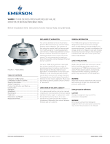
ASSEMBLY INSTRUCTIONS
1. Check that all components are clean and
that there is no damage that will affect the
performance of the rebuilt valve. On fire
safe valves, specific care should be taken in
inspecting the fire safe lip to ensure that it
is free from nicks or other imperfections.
2. Cantilever seat assembly: Place seat (101)
in each seat pocket body (001) and body
insert (002)
2.1 Cantilever O-ring seat assembly:
PlaceO-ring (110) followed by seat (101)
ineach seat pocket body (001) and body
insert (002)).
2.2 Energized seat assembly: Place a seat
spring (104) into each seat pocket (body
(001) and body insert (002)), followed by a
preassembled energized seat assembly
with care, making certain that O-ring
(106) is not damaged when pushing seat
assembly down into seat pockets.
3. Place the primary stem seal (201) and fire
safe stem seal (202) onto the base of the
stem (200). Insert the stem (200) into the
valve body (001) from inside the bore of
thevalve.
4. Whilst holding the stem in position, fit
auxiliary stem seal (235), followed by
weather seal (251), followed by stem seal
follower (223), followed by stop plate (205).
5. Fit the stem spring (206).
6. Fit the lock washer (258) (DN 50 valve only).
Lubricate thread with anti-seize compound
and screw down the stem nut (207) hand
tight.
8. Place the other seat/seat assembly into
position and fit the body insert seal (003)
into the body cavity.
9. Lubricate the thread on the body insert with
copper-based grease.
10. Screw in the body insert (002) and tighten
down to recommended torque - refer table
or until the insert is level with the flange
face, but no more than 0.25 mm below.
11. For DN 50 valves, tighten down the stem
nut (207) to recommended gland torque and
back off until the flat lines up with the tab
on the lock washer (258). Bend up the lock
washer to lock the nut in this position.
12. For DN 80 and larger valves, tension stem
until the stem spring is fully compressed,
then back off a quarter of a turn and lock
into position with upper stem nut.
13. Refit wrench assembly.
14. Check the valve for operation, it should
be smooth and firm during the cyclic
operation. If possible, perform a pressure
test on the bench to ensure that the valve
has been correctly reassembled.
TORQUE VALUES (Nm)
Valve size
DN
Gland torque
(Nm)*
Body insert
torque (Nm)
NOTE:
* Tighten to correct torque and back off to nearest flat
on nut
7. Ensure that the stem (200) is in the closed
position and slip the ball (100) into position
in the valve body (001). Note; For DN 50
valve ensure that the anti-static device (532)
is in position as the ball is inserted.
Neither Emerson, Emerson Automation Solutions, nor any of their affiliated entities assumes responsibility for the selection, use or maintenance of any product.
Responsibility for proper selection, use, and maintenance of any product remains solely with the purchaser and end user.
KTM is a mark owned by one of the companies in the Emerson Automation Solutions business unit of Emerson Electric Co. Emerson Automation Solutions, Emerson and
the Emerson logo are trademarks and service marks of Emerson Electric Co. All other marks are the property of their respective owners.
The contents of this publication are presented for informational purposes only, and while every effort has been made to ensure their accuracy, they are not to be
construed as warranties or guarantees, express or implied, regarding the products or services described herein or their use or applicability. All sales are governed by
our terms and conditions, which are available upon request. We reserve the right to modify or improve the designs or specifications of such products at any time without
notice.
Emerson.com/FinalControl
/