
1
Operating Instructions and Parts Manual
8-inch Grinder with Belt Sander
Models IBGB-248/248VS/436/436VS
JET
427 New Sanford Road Part No. M-577248
LaVergne, Tennessee 37086 Edition 4 10/2019
Ph.: 800-274-6848 ECR 191025080920
www.jettools.com Copyright © 2019 JET
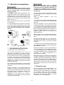
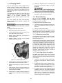
Variable speed model IBGB-436VS shown
for models with serial no. 19120001 and higher.
This .pdf document is bookmarked

2
1.0 IMPORTANT SAFETY
INSTRUCTIONS
WARNING – To reduce risk of injury:
1. Read and understand the entire owner's
manual before attempting assembly or
operation.
2. Read and understand the warnings posted on
the machine and in this manual. Failure to
comply with all of these warnings may cause
serious injury.
3. Replace warning labels if they become
obscured or removed.
4. This bench grinder is designed and intended for
use by properly trained and experienced
personnel only. If you are not familiar with the
proper and safe operation of a bench grinder,
do not use until proper training and knowledge
have been obtained.
5. Do not use this bench grinder for other than its
intended use. If used for other purposes, JET
disclaims any real or implied warranty and holds
itself harmless from any injury that may result
from that use.
6. Always wear protective eye wear when
operating machinery. Eye wear shall be impact
resistant, protective safety glasses with side
shields which comply with ANSI Z87.1
specifications. Use of eye wear which does not
comply with ANSI Z87.1 specifications could
result in severe injury from breakage of eye
protection. (Everyday eyeglasses only have
impact resistant lenses; they are NOT safety
glasses.)
7. Use the grinder’s eye shields and spark guards.
Also use respiratory protection if the grinding or
sanding operation is dusty.
8. Wear proper apparel. Do not wear loose
clothing, neckties, rings, bracelets, or other
jewelry which may get caught in moving parts.
Non-slip footwear is recommended. Wear
protective hair covering to contain long hair.
9. Wear protective clothing such as apron or
safety shoes, where the grinding activity
presents a hazard to the operator.
10. Wear ear protectors (plugs or muffs) if the
particular work requires it.
11. Do not operate this machine while tired or under
the influence of drugs, alcohol or any
medication.
12. Make certain the switch is in the OFF position
before connecting the machine to the power
supply.
13. Make certain the machine is properly grounded.
14. Make all machine adjustments or maintenance
with the machine unplugged from the power
source.
15. Remove adjusting keys and wrenches. Form a
habit of checking to see that keys and adjusting
wrenches are removed from the machine
before turning it on.
16. Keep safety guards in place at all times when
the machine is in use. If removed for
maintenance purposes, use extreme caution
and replace the guards immediately after
completion of maintenance.
17. Check damaged parts. Before further use of the
machine, a guard or other part that is damaged
should be carefully checked to determine that it
will operate properly and perform its intended
function. Check for alignment of moving parts,
binding of moving parts, breakage of parts,
mounting and any other conditions that may
affect its operation. A guard or other part that is
damaged should be properly repaired or
replaced.
18. Provide for adequate space surrounding work
area and non-glare, overhead lighting.
19. Keep the floor around the machine clean and
free of scrap material, oil and grease.
20. Keep visitors a safe distance from the work
area. Keep children away.
21. Make your workshop child proof with padlocks,
master switches or by removing starter keys.
22. Give your work undivided attention. Looking
around, carrying on a conversation and “horse-
play” are careless acts that can result in serious
injury.
23. Keep proper footing and balance at all times so
that you do not fall into or lean against the
grinding wheel or other moving parts. Do not
overreach or use excessive force to perform
any machine operation.
24. Disconnect grinder from power source before
servicing and when changing abrasive wheel or
sanding belt.
25. Use recommended accessories. The use of
improper accessories may cause risk of injury
to persons.
26. Turn off the machine before cleaning. Use a
brush to remove chips or debris — do not use
bare hands.

3
27. Never leave grinder running unattended. Turn
power off and do not leave machine until wheel
comes to a complete stop.
28. Remove loose items and unnecessary work
pieces from the area before starting the grinder.
29. Don’t use in dangerous environment. Don’t use
power tools in damp or wet location, or expose
them to rain. Don’t use this grinder in a
flammable environment. Keep work area well
lighted.
30. Keep work area clean. Cluttered areas and
benches invite accidents.
31. Use the right tool. Don't force tool or attachment
to do a job for which it was not designed.
32. Use proper extension cord. Make sure your
extension cord is in good condition. When using
an extension cord, be sure to use one heavy
enough to carry the current your product will
draw. An undersized cord will cause a drop in
line voltage resulting in loss of power and
overheating. Table 1 (see sect. 6.2) shows the
correct size to use depending on cord length
and nameplate ampere rating. If in doubt, use
the next heavier gage. The smaller the gage
number, the heavier the cord.
33. Maintain tools with care. Keep tools sharp and
clean for best and safest performance. Follow
instructions for lubricating and changing
accessories.
34. Direction of feed: Feed work into a blade or
cutter against the direction of rotation of the
blade or cutter only.
35. Do not overtighten wheel nut.
36. Frequently clean grinding dust from beneath
grinder.
37. Use grinding wheel suitable for speed of
grinder.
38. Inspect abrasive wheels for cracks or other
forms of damage. Perform a “ring test” to check
wheel integrity. Do not use a faulty or damaged
wheel.
39. Verify that maximum RPM of abrasive wheels is
compatible with speed of grinder. Do not
remove the blotter (label) from either side of a
grinding wheel.
40. Allow abrasive wheel to reach full RPM before
starting the grinding operation.
41. Do not crowd the work so that the wheel slows.
42. Tool rests should be adjusted to approximately
1/16” from wheel surface.
43. Do not grind on the side of a wheel; do all work
on the grinding face or edge near the tool rest.
44. Do not grind aluminum or magnesium, as these
may pose a fire hazard.
45. Use only the flanges that are furnished with the
grinder.
46. Do not start the grinder while a workpiece is
contacting the grinding wheel or the sanding
belt.
Familiarize yourself with the following safety notices used in this manual:
This means that if precautions are not heeded, it may result in minor injury and/or
possible machine damage.
This means that if precautions are not heeded, it may result in serious, or possibly even
fatal, injury.
WARNING: This product can expose you to
chemicals including lead which is known to the
State of California to cause cancer and birth
defects or other reproductive harm. For more
information go to http://www.p65warnings.ca.
gov.
WARNING: Some dust, fumes and gases
created by power sanding, sawing, grinding,
drilling, welding and other construction activities
contain chemicals known to the State of
California to cause cancer and birth defects or
other reproductive harm. Some examples of
these chemicals are:
lead from lead based paint
crystalline silica from bricks, cement and
other masonry products
arsenic and chromium from chemically
treated lumber
Your risk of exposure varies, depending on how
often you do this type of work. To reduce your
exposure to these chemicals, work in a well-
ventilated area and work with approved safety
equipment, such as dust masks that are
specifically designed to filter out microscopic
particles. For more information go to
http://www.p65warnings.ca. gov/ and http://www
.p65warnings.ca.gov/wood.

4
2.0 Table of contents
Section Page
1.0 IMPORTANT SAFETY INSTRUCTIONS ....................................................................................................... 2
2.0 Table of contents ............................................................................................................................................ 4
3.0 About this manual .......................................................................................................................................... 5
4.0 Specifications ................................................................................................................................................. 6
4.1 Mounting hole dimensions .......................................................................................................................... 7
4.2 Machine dimensions/work area .................................................................................................................. 8
5.0 Carton contents .............................................................................................................................................. 9
6.0 Setup and assembly ..................................................................................................................................... 10
6.1 Tools required for assembly ..................................................................................................................... 10
6.2 Unpacking ................................................................................................................................................ 10
6.3 Securing the grinder ................................................................................................................................. 10
6.4 Assembling eye shield bracket to spark guard ......................................................................................... 10
6.5 Installing spark guard/bracket .................................................................................................................. 10
6.6 Eye shield ................................................................................................................................................. 10
6.7 Grinder tool rest ........................................................................................................................................ 10
6.8 Sanding table ........................................................................................................................................... 11
6.9 Stand-off ................................................................................................................................................... 11
6.10 Sanding tool rest .................................................................................................................................... 11
6.11 Dust port ................................................................................................................................................. 11
7.0 Electrical connections .................................................................................................................................. 12
7.1 GROUNDING INSTRUCTIONS ............................................................................................................... 12
7.2 Extension cords ........................................................................................................................................ 12
7.3 Voltage conversion ................................................................................................................................... 13
8.0 Adjustments ................................................................................................................................................. 13
8.1 Eye shield tilt adjustment .......................................................................................................................... 13
8.2 Spark guard .............................................................................................................................................. 13
8.3 Tool rest ................................................................................................................................................... 13
8.4 Sanding arm tilt ........................................................................................................................................ 13
8.5 Sanding belt tracking ................................................................................................................................ 13
9.0 Operation ..................................................................................................................................................... 14
9.1 Operating controls .................................................................................................................................... 14
9.2 Precautions .............................................................................................................................................. 15
10.0 User-maintenance ...................................................................................................................................... 15
10.1 Installing/replacing sanding belt ............................................................................................................. 15
10.2 Care of grinding wheels .......................................................................................................................... 15
10.3 Ring test ................................................................................................................................................. 15
10.4 Changing wheels .................................................................................................................................... 16
10.5 Wheel balancing ..................................................................................................................................... 16
10.6 Dressing the wheel ................................................................................................................................. 17
10.7 Wire wheel brushes ................................................................................................................................ 17
10.8 Cleaning ................................................................................................................................................. 17
10.9 Tension lever tightness .......................................................................................................................... 17
10.10 Lubrication ............................................................................................................................................ 17
10.11 Additional servicing .............................................................................................................................. 17
11.0 Optional accessories .................................................................................................................................. 18
12.0 Troubleshooting IBGB series Sander/Grinder ............................................................................................ 19
12.1 General mechanical and electrical problems ......................................................................................... 19
12.2 Digital readout error codes (Variable speed models) ............................................................................. 20
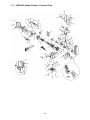
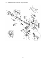
13.0 Replacement Parts ..................................................................................................................................... 21
13.1.1 IBGB-248 Sander/Grinder – Exploded View ....................................................................................... 22
13.1.2 IBGB-248 Sander/Grinder – Parts List ................................................................................................ 23
13.2.1 IBGB-248VS Sander/Grinder – Exploded View .................................................................................. 25
13.2.2 IBGB-248VS Sander/Grinder – Parts List ........................................................................................... 26
13.3.1 IBGB-436 Sander/Grinder – Exploded View ....................................................................................... 28
13.3.2 IBGB-436 Sander/Grinder – Parts List ................................................................................................ 29
13.4.1 IBGB-436VS Sander/Grinder – Exploded View .................................................................................. 31
13.4.2 IBGB-436VS Sander/Grinder – Parts List ........................................................................................... 32
14.0 Electrical Connections ................................................................................................................................ 34

5
14.1 Wiring diagram for IBGB-248 and IBGB-436 ......................................................................................... 34
14.2 Wiring diagram for IBGB-248VS and IBGB-436VS ................................................................................ 34
15.0 Warranty and service ................................................................................................................................. 35
3.0 About this manual
This manual is provided by JET, covering the safe operation and maintenance procedures for a JET Model IBGB
series Grinder/Belt Sander. This manual contains instructions on installation, safety precautions, general
operating procedures, maintenance instructions and parts breakdown. Your machine has been designed and
constructed to provide consistent, long-term operation if used in accordance with the instructions set forth in this
document.
The operator is encouraged to familiarize him/herself with ANSI B7.1 – Safety Requirements for Use, Care and
Protection of Abrasive Wheels.
If there are questions or comments, please contact your local supplier or JET. JET can also be reached at our
web site: www.jettools.com.
Retain this manual for future reference. If the machine transfers ownership, the manual should accompany it.
Read and understand the entire contents of this manual before attempting assembly or
operation! Failure to comply may cause serious injury!
Register your product using the provided mail-in card, or register online:
http://www.jettools.com/us/en/service-and-support/warranty/registration/

6
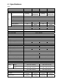
4.0 Specifications
Table 1
Stock number
577248 578248 577436 578436
Model number IBGB-248VS IBGB-248 IBGB-436VS IBGB-436
Motor and Electricals
Motor
Type
Induction,
with inverter
Induction,
capacitor start,
centrifugal switch
Induction,
with inverter
Induction,
capacitor start,
centrifugal switch
Horsepower 1HP
Phase single
Voltage 115/230V, prewired 115V
Cycle 60 Hz
Listed FLA (full load amps) 7 / 3.5 A 11 / 5.5 A 7 / 3.5 A 11 / 5.5 A
Starting capacitor n/a
200MFD,
125VAC
n/a
200MFD,
125VAC
Running capacitor
n/a
35µF, 250V n/a 35µF, 250V
Input power required
Single phase 115V (or single phase 230V if rewired)
On/off switch TACT toggle TACT toggle
Power transfer Direct drive
Power cord SJT 16AWG x 3C, 6 ft. (183cm)
Power plug provided 5-15P, 125V/15A
Recommended circuit size
1
15 A
Sound emission without load
2
75 dB at 3 ft. (92cm)
Grinding wheel and shaft
Arbor diameter 5/8 in. (16 mm)
Grinding wheel size (OD x W x Bore) 8 x 1 x 5/8 in.
Grinding wheel grit provided 36
Grinding wheel speed (RPM) 900~3600 3600 900~3600 3600
Grinding wheel material Aluminum oxide
Belt sander
Sanding belt size (L x W) 48 x 2 in. (1219 x 50.8 mm) 36 x 4 in. (914.4 x 101.6 mm)
Sanding belt grit provided 80
Belt speed (SFPM) 1178~4712 4,712 942~3769 3,769
Sanding belt material Aluminum oxide
Sanding table tilt 45 deg. down
Sanding table size 4-11/32 x 2-15/16 in. (110 x 75mm) 6-5/16 x 2-15/16 in. (160 x 75mm)
Tool rest tilt 45 deg. down
Tool rest size (L x W) 3-1/8 x 2-5/8 in. (79 x 67mm) 5-1/8 x 3-1/8 in. (130 x 80mm)
Drive wheel size (Dia. x W) 5 x 2-1/16 in. (127.5 x 53mm) 4 x 4-1/16 (102.5 x 104mm)
Dust port diameter 2 in. (50.8mm)
Recommended min. dust extraction 350 CFM
Dimensions
Foot print (W x D) 9-1/2 W x 8-1/16 in. (241 x 204.8 mm)
Overall
dimensions
(LxWxH)
Sanding bracket
vertical
21-1/4 x 12-9/32 x 25-29/32 in.
(539 x 312 x 658 mm)
23-7/32 x 12-7/32 x 20-3/4 in.
(590 x 310 x 527 mm)
Sanding bracket
parallel
21-1/4 x 24-3/4 x 13-15/16 in.
(539 x 629 x 354 mm)
23-7/32 x 19-1/2 x 13-15/16 in.
(590 x 496 x 354 mm)
Shipping dimensions (L x W x H)
26-9/16 x 24-19/32 x 16-15/16 in.
(675 x 625 x 430 mm)
21-15/32 x 24-19/32 x 16-15/16 in.
(545 x 625 x 430 mm)
Weights
Net weight
78 lbs.
(35.30kg)
77 lbs.
(35.02 kg)
77 lbs.
(34.95 kg)
76 lbs.
(34.65 kg)
Shipping weight
96 lbs.
(43.66 kg)
95 lbs.
(43.38 kg)
93 lbs.
(42.04 kg)
92 lbs.
(41.74 kg)

7
IBGB-248VS IBGB-248 IBGB-436VS IBGB-436
Main materials
Grinder
Motor housing Sheet metal
End cover Aluminum (Grinder side) / Cast iron (Belt sander side)
Base Cast iron
Tool rest Cast iron
Inner wheel guard Cast iron
Outer wheel guard Aluminum
Flange washer Cast iron
Eye shield Polycarbonate
Sander
Belt table Cast iron
Belt table bracket Sheet metal
Tool rest Sheet metal
Tool rest bracket Sheet metal
1
subject to local and national electrical codes.
2
The specified values are emission levels and are not necessarily to be seen as safe operating levels. As workplace
conditions vary, this information is intended to allow the user to make a better estimation of the hazards and risks
involved only.
L = length, W = width, H = height, D = depth
OD = outside diameter
n/a = not applicable
The specifications in this manual were current at time of publication, but because of our policy of continuous
improvement, JET reserves the right to change specifications at any time and without prior notice, without incurring
obligations.
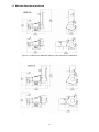
4.1 Mounting hole dimensions
Figure 4-1 Mounting dimensions, all models

8
4.2 Machine dimensions/work area
Figure 4-2: dimensions for IBGB-248/-248VS (primary dimensions in millimeters)
Figure 4-3: dimensions for IBGB-436/-436VS (primary dimensions in millimeters)

9
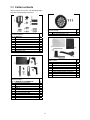
5.0 Carton contents
Refer to Figures 5-1 thru 5-4. The identifying letters
are used in the assembly instructions.
Figure 5-1
Eye shield hardware
Part no. IBG8-100
Qty.
A Spark guard 1
B Lock knob 1
C Flat washer, 1/4" 1
D Eye shield bracket 1
E Eye shield plate 1
F Hex cap screw, 3/8 x 5/8" 2
G Hex cap screw, 3/8 x 1/2" 2
H Truss head screw, 3/16 x 1/2” 2
J Flat washers 3/8” 4
Figure 5-2
Hardware package
Part no. IBGB248-HP or IBGB436-HP
Qty.
K Tool rest (for sanding belt) 1
L Flat washer 3/8 1
M Adjustable handle 3/8 x 5/8L 1
N Stand-off 1
O Socket hd cap screw 5/16 x 1/2 1
P Flat washer 5/16 1
R Ext. tooth lock washer M8 1
S Bracket plate 1
T Flat washer 5/16 1
U Adjustable handle 5/16 x 1L 1
Figure 5-3
Dust port package Qty.
Dust port 1
Truss head screw 3/16 x 3/8 3
Figure 5-4
Additional items Qty.
V Eye shield 1
W Sanding table 1
X Hex wrench 6 x 140L mm 1
Y Grinder tool rest 1
Z Wheel dresser 1
Grinder with Belt Sander (not shown) 1
Sanding belt 80G (preinstalled) 1
Grinding wheel 36G (preinstalled) 1

10
6.0 Setup and assembly
6.1 Tools required for assembly
Cross-point (Phillips) screwdriver
14mm (or adjustable) wrench
3mm hex wrench
6mm hex wrench
6.2 Unpacking
Separate all parts from the packing material. Check
each part against sect. 5.0, Carton contents, and
make certain that all items are accounted for.
(Check whether any parts have been pre-mounted
to the grinder.) Notify your dealer or JET if missing
or damaged items are discovered. Do not discard
any packing material until grinder is assembled and
operating properly.
The IBGB Grinder/Belt Sander requires only
minimal assembly. Additional tools may be needed
for fastening the grinder to a workbench or stand.
For your safety, do not plug the grinder into a power
source until all assembly and adjustments are
complete.
Make sure that bench grinder is
unplugged and power switch is in OFF position.
Do not plug in the grinder to power until it is
inspected for shipping damage, fully
assembled, and moved to its permanent
location. Failure to comply may cause serious
injury.
Do not operate this machine
without all guards and shields in place and in
working order. Failure to comply may cause
serious injury.
Chipped or cracked wheels can
break up and cause serious damage to the
grinder and/or severe injury to the operator.
Regularly inspect wheels for damage.
6.3 Securing the grinder
To prevent the machine from moving during
operation, it should be securely mounted to a work
bench or grinder stand. Fasteners for mounting are
not included with the grinder.
1. Align mounting holes on grinder with predrilled
holes in bench or grinder stand. Figure 4-1
shows hole centers for mounting.
2. Insert M10 (or 3/8”) bolts through the holes and
secure with washers and nuts.
An optional JET pedestal stand (not included) is
available for your grinder. See sect. 11.0.
IMPORTANT: The grinder’s base plate contains
ventilation holes for heat dissipation. This is
especially important on the variable speed models,
as it helps keep the circuit board at an acceptable
temperature. These holes should not be obstructed.
If the rubber pads are removed for mounting to a
table, allow an opening in the table below the grinder
for air circulation. However, it is recommended the
rubber pads be left on, as they allow air circulation
as well as vibration dampening.
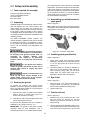
6.4 Assembling eye shield bracket to
spark guard
Refer to Figure 6-1.
Note: Spark guard (A) and eye shield bracket (D)
are marked L for left side assembly. Assemble these
using Figure 6-1 as a guide.
Figure 6-1: bracket to spark guard
6.5 Installing spark guard/bracket
Refer to Figure 6-2.
1. Install spark guard and mounting bracket
assembly to the left wheel housing with two 3/8
x 1/2” hex cap screws (G) and two 3/8" flat
washers (J).
2. The spark guard (A
1
) should be adjusted to
within 1/16" of the grinding wheel surface or
other accessory being used. As the wheel
wears down, the spark guard must be re-
adjusted to maintain this 1/16" distance.
6.6 Eye shield
Refer to Figure 6-2.
1. Insert two 3/16” x 1/2” truss head screws (H)
through bracket, eye shield (V), and plate (E)
which contains threaded mounting holes.
2. Tighten screws (H).
6.7 Grinder tool rest
Refer to Figure 6-2.
1. Install tool rest (Y) by inserting two 3/8" x 3/4"
hex cap screws (F) through two 3/8" flat
washers (J), through the tool rest (Y), into the
wheel housing.
2. The tool rest should be adjusted to within 1/16"
of the grinding wheel or other accessories being
used. As the wheel wears down, the tool rest

11
must be readjusted to maintain a maximum
1/16" clearance.
Figure 6-2: guard and tool rest
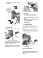
6.8 Sanding table
Install bracket plate, table and handles, as shown in
Figure 6-3.
Figure 6-3: sanding belt table
The quickest method of installing a handle is to start
the handle into the threads of the hole, then pull out
on the handle while turning the screw with a 3mm
hex wrench until tight. See Figure 6-4.
To reposition a handle for convenience without
affecting its tightness, pull out on it, rotate, then
release it, allowing it to resettle upon the screw.
Figure 6-4: installing handles
6.9 Stand-off
1. Install stand-off (shown installed in Figure 8-2)
into threaded hole in back of sanding arm.
2. Loosen screw (A, Figure 6-5) with 6mm hex
wrench and lower sanding arm to horizontal
position.
3. Turn stand-off in or out as needed until sanding
arm is level with workbench.
4. Tighten hex nut against sanding arm to secure
setting of stand-off.
6.10 Sanding tool rest
Loosen screw (A, Figure 6-5) with 6mm hex wrench
and lower sanding arm to horizontal position.
Install tool rest as shown in Figure 6-5, using a 6mm
hex wrench.
Note: The tool rest can remain installed when not in
use. Simply adjust it outward to allow opening and
closing of drive wheel cover. Adjust it inward before
raising arm to vertical position.
Figure 6-5: Sanding tool rest
6.11 Dust port
Install dust port (B, Figure 6-5) over exhaust hole in
sanding arm, with three screws.
It is recommended that a dust collection system
designed for metal dust and shavings be connected
to the ports on grinder and belt sander, using 2-1/2”
inside diameter hose with hose clamp (not
provided).

12
7.0 Electrical connections
Electrical connections should
be made by a qualified electrician in compliance
with all relevant codes. This tool must be
properly grounded.
The IBGB Grinder/Belt Sander is prewired for 115V
single phase power, and is supplied with a plug
designed for use on a circuit with a grounded outlet
that looks like the one pictured in A, Figure 7-1. The
grinder may be converted to 230V single phase
power, see sect. 7.3.
Before connecting to power source, be sure switch
is in off position.
It is recommended that the grinder be connected to
a 15-amp circuit with circuit breaker or fuse. If using
fuses, they should be time-delay fuses marked “D”.
Local codes take precedence over recommen-
dations.
Figure 7-1: plug configurations
7.1 GROUNDING INSTRUCTIONS
1. All Grounded, Cord-connected Tools:
This tool must be grounded. In the event of a
malfunction or breakdown, grounding provides a
path of least resistance for electric current to reduce
the risk of electric shock. This tool is equipped with
an electric cord having an equipment-grounding
conductor and a grounding plug. The plug must be
plugged into a matching outlet that is properly
installed and grounded in accordance with all local
codes and ordinances.
Do not modify the plug provided - if it will not fit the
outlet, have the proper outlet installed by a qualified
electrician.
Improper connection of the equipment-grounding
conductor can result in a risk of electric shock. The
conductor with insulation having an outer surface
that is green with or without yellow stripes is the
equipment-grounding conductor. If repair or
replacement of the electric cord or plug is
necessary, do not connect the equipment-grounding
conductor to a live terminal.
Check with a qualified
electrician or service personnel if the grounding
instructions are not completely understood, or if
in doubt as to whether the tool is properly
grounded. Failure to comply may cause serious
or fatal injury.
Use only 3-wire extension cords that have 3-prong
grounding plugs and 3-pole receptacles that accept
the tool's plug.
Repair or replace damaged or worn cord
immediately.
2. Grounded, cord-connected tools intended for use
on a supply circuit having a nominal rating less than
150 volts:
This tool is intended for use on a circuit that has an
outlet that looks like the one illustrated in A, Figure
7-1. An adapter, shown in B and C, may be used to
connect this plug to a 2-pole receptacle as shown in
B if a properly grounded outlet is not available. The
temporary adapter should be used only until a
properly grounded outlet can be installed by a
qualified electrician.
Note: In Canada, the use of a temporary adaptor is
not permitted by the Canadian Electrical Code,
C22.1.
The green-colored rigid ear, lug, and the like,
extending from the adapter must be connected to a
permanent ground such as a properly grounded
outlet box.
3. Grounded, cord-connected tools intended for use
on a supply circuit having a nominal rating between
150 - 250 volts, inclusive:
This tool is intended for use on a circuit that has an
outlet that looks like the one illustrated in D, Figure
7-1. A grounding plug may be installed, that looks
like the plug illustrated in D; or the grinder may be
“hard-wired” to a panel, provided there is a
disconnect for the operator.
Make sure the tool is connected to an outlet having
the same configuration as the plug. No adapter is
available or should be used with this tool. If the tool
must be reconnected for use on a different type of
electric circuit, the reconnection should be made by
qualified service personnel; and after reconnection,
the tool should comply with all local codes and
ordinances.
7.2 Extension cords
The use of extension cords is discouraged. Try to
position equipment near the power source. If an
extension cord becomes necessary, use only three-
wire extension cords that have three-prong
grounding type plugs and three-prong receptacles
that accept the tool's plug. Replace or repair
damaged or worn cord immediately.

13
Make sure your extension cord is in good condition,
and is heavy enough to carry the current your
product will draw. An undersized cord will cause a
drop in line voltage resulting in loss of power and
overheating.
Table 2 shows the correct size to use depending on
cord length and nameplate ampere rating. If in
doubt, use the next heavier gage. The smaller the
gage number (AWG), the heavier the cord.
Ampere
Rating
Volts
Total length of
cord in feet
More
Than
Not
More
Than
120
240
25
50
50
100
100
200
150
300
AWG
0 6 18 16 16 14
6 10 18 16 14 12
10 12 16 16 14 12
12 16 14 12
Not
Recommended
Extension Cord Recommendations
Table 2
7.3 Voltage conversion
The grinder/belt sander is prewired for 115 volt input
power, but can be converted to 230 volt input, as
follows.
7.3.1 Non-variable speed models (IBGB-
248 and IBGB-436)
1. Turn grinder over and remove base plate.
2. Reconnect the leads according to wiring
diagram in sect. 13.0.
3. Remove existing plug from power cable and
attach a UL/CSA listed plug designed for 230V
power.
7.3.2 Variable speed models (IBGB-
248VS and IBGB-436VS)
Remove existing plug from power cable and attach
a UL/CSA listed plug designed for 230V power.
8.0 Adjustments
8.1 Eye shield tilt adjustment
1. Loosen lock knob (A
1
, Figure 8-1).
2. Adjust eye shield (A
2
) to desired tilt angle.
3. Tighten lock knob.
Figure 8-1: eye shield adjustment
8.2 Spark guard
As the wheel wears down, the spark guard must be
re-adjusted to maintain a 1/16" distance.
Refer to Figure 8-1.
1. Loosen two hex cap screws (B
1
) with 14mm
wrench.
2. Slide spark guard (B
2
) to 1/16" distance from
grinding wheel surface.
3. Tighten screws (B
1
).
8.3 Tool rest
As the wheel wears down, the tool rest must be re-
adjusted to maintain a 1/16" distance.
Refer to Figure 8-1.
1. Loosen two hex cap screws (C
1
) with 14mm
wrench.
2. Slide tool rest (C
2
) to a distance of 1/16" from
grinding wheel.
3. Tighten screws (C
1
).
8.4 Sanding arm tilt
Loosen screw (A, Figure 6-5) and manually move
arm to vertical or horizontal position. Retighten
screw.
Make sure screw is tight when
using sanding arm. Failure to comply may result
in vertical sanding arm falling back into
horizontal position during operation, resulting
in possible injury.
8.5 Sanding belt tracking
1. Turn grinder/sander OFF.
2. Move sanding belt by hand to check tracking. If
belt migrates to one side or the other, adjust as
follows.
3. Loosen wing nut (E, Figure 8-2).

14
4. Turn knob (F) while moving the belt until belt
completely covers drive wheel and stays
centered. Turn handle clockwise to shift belt to
the right (away from grinder), counterclockwise
to shift belt to the left (toward grinder). NOTE:
This adjustment is sensitive, turn handle in
small increments and allow belt to respond to
changes.
5. Tighten wing nut (E) to secure setting.
6. Turn on machine to verify setting at low speed.
Figure 8-2: belt tracking
9.0 Operation
A bench grinder is designed for hand-grinding
operations such as sharpening chisels,
screwdrivers, drill bits, removing excess metal, and
smoothing and polishing metal surfaces.
Always use approved safety
glasses or face shield while operating tool.
Failure to comply may cause serious injury.
The IBGB Grinder/Sander offers multiple working
methods:
Grinding wheel – A medium-grain, 36-grit wheel is
provided, and is effective when a considerable
amount of metal must be removed, or when
obtaining a smooth finish is not important. A finer
grain abrasive grinding wheel (not provided) can be
mounted for sharpening tools or grinding to close
size tolerances because it removes metal more
gradually for precision grinding and achieves a
smoother finish.
Belt and platen (horizontal or vertical position) –
Workpieces of any length can be worked on the belt
and against the platen. The table or tool rest should
be tightened in place and used to support the
workpiece. The table can tilt down to 45-degrees,
and may also be used as a fence for workpiece
support when sanding arm is horizontal.
The general-purpose 80-grit sanding belt is useful
for many applications, including radiusing, deburring
and finishing/polishing of both ferrous and non-
ferrous alloys.
Contour sanding (horizontal position) – Contoured
workpieces can be sanded over the drive wheel.
Open end cover, adjust tool rest and tighten in
place.
9.1 Operating controls
Note: After extended operation, the grinder housing
may be warm to the touch. This is not abnormal.
IBGB-248, IBGB-436: Pull paddle switch (A, Figure
9-1) to start tool, push to stop. The safety key (A
1
)
can be removed to prevent unauthorized use of the
grinder. The safety key must be inserted to restart
the grinder.
Figure 9-1: safety key
IBGB-248VS, IBGB-436VS: Press on/off button on
keypad (Figure 9-2) to start or stop. Press either of
the numbered buttons to start machine at the
designated speed. Press arrow buttons to change
rotation speed in 100 RPM increments.
The digital readout will flash briefly during start up
and speed adjustments. Press button to toggle
between RPM and SFPM display.
The grinder will automatically shut off after
approximately 1-1/2 minutes of inactivity.
Figure 9-2: keypad (VS models only)

15
9.2 Precautions
9.2.1 Wheel grinding
1. Before starting grinder, turn grinding wheel by
hand to verify that it is clear of obstruction and
turns freely. The tool rest and spark guard
should not touch the wheel.
2. Keep tool rest and spark guard to within 1/16"
of grinding wheel.
3. Turn on grinder and allow it to reach full running
speed before starting to grind.
4. Adjust the eye shield as needed.
5. Keep a steady, moderate pressure on the
workpiece and keep it moving at an even pace
for smooth grinding. Pressing too hard
overheats the motor and prematurely wears the
grinding wheel. Note the original bevel angle on
the item to be sharpened and try to maintain the
same shape. The grinding wheel should rotate
into the object being sharpened.
6. If grinding a narrow workpiece, slide it laterally
across width of wheel. Using full width of wheel
will help prevent a groove from forming at one
place on the wheel.
7. Keep a water pot filled with water and dip your
work into it regularly to prevent overheating.
Overheating can weaken metals. Do not apply
water directly to grinding wheel.
8. Do not use the side of the grinding wheel; this
puts dangerous stress on the wheel.
9. When wheel becomes loaded or dull, use an
approved grinding wheel dresser and dress the
wheel face.
10. At all times, keep hands and fingers away from
pinch points.
9.2.2 Belt sanding
1. Move belt by hand to ensure that wheels rotate
freely without obstruction, table or tool rest does
not contact belt, and belt tracks properly.
2. Use the entire width of the belt to reduce wear
in one place.
3. At all times, keep hands and fingers away from
pinch points.
10.0 User-maintenance
For safety, turn switch to OFF and remove plug from
power source outlet before performing maintenance
on the grinder/sander.
If the power cord is worn, cut or damaged in any
way, have it replaced immediately.
10.1 Installing/replacing sanding belt
1. Disconnect grinder/sander from power source.
2. Unscrew knobs and open side guard and drive
wheel cover.
3. Pull tension lever (D, Figure 10-1) outward to
compress spring and de-tension belt.
4. Remove old belt by sliding it off wheels. Install
new belt, centering it on the wheels. Make sure
arrow printed on back of sanding belt matches
direction of belt movement.
5. Push lever (D) inward to tension belt.
6. Verify proper belt tracking, sect. 8.5.
7. Close side cover and secure with knobs before
operating.
Figure 10-1: installing sanding belt
10.2 Care of grinding wheels
In normal use, grinding wheels may become
cracked, grooved, rounded at the edges, chipped,
out of true or loaded with foreign material.
Cracked wheels should be replaced
IMMEDIATELY. The other conditions can be
remedied with a dressing tool. New wheels
sometimes require dressing to make them round.
See sect. 10.5.
10.3 Ring test
Before replacing a grinding wheel, perform this
simple test on the replacement wheel:
1. Loop a piece of string through the grinding
wheel hole and suspend the wheel by holding
up the string.
2. Tap the wheel with a scrap of wood or wooden
dowel.
3. A good wheel will "ring"; a defective wheel will
"thud". Discard any wheel that does not "ring".
An internal defect may not be apparent by visual
inspection alone. The ring test may identify an
internal crack or void.

16
10.4 Changing wheels
The JET bench grinder comes equipped with a
general purpose grinding wheel. Wheels vary
according to types of abrasive, hardness, grit size,
and structure. Contact your local distributor for the
proper grinding wheel or wire wheel brush for your
application.
If you replace a wheel, obtain one with a safe rated
speed at least as high as the NO LOAD RPM
marked on the grinder's nameplate. The
replacement wheel must be 8” OD x 1” W x 5/8”
Bore.
The bench grinder will accept most polishing,
buffing, and wire wheels available at dealers and
hardware stores.
The use of any other accessory
is not recommended and may result in serious
injury.
To change a wheel (see Figure 10-2):
1. Disconnect grinder from power source.
2. Loosen spark guard (B) and tool rest (C) and
move them away from the wheel.
3. Remove wheel guard using a cross-point or
flathead screwdriver.
4. Stabilize wheel by placing a wood wedge
between wheel and tool rest.
Figure 10-2: wheel replacement
5. Unscrew arbor nut (D) with wrench. Note: Left-
hand threads; turn nut clockwise to loosen.
6. Remove outer flange (E), wheel (F), and inner
flange.
7. Clean flanges. Check the flanges to make sure
they are flat. Wheel flanges that are not flat will
cause the wheel to wobble.
8. Inspect the new grinding wheel and perform a
“ring test” (sect. 10.3). Do not install a damaged
wheel.
9. Install inner flange, wheel (F), outer flange (E)
and nut (D) on the shaft. Tighten nut counter-
clockwise.
Do not overtighten nut; this
may cause the wheel to crack. Maximum
safe torque on nut is 20 lbf•ft (270 kgf•cm).
10. Reinstall wheel guard. Adjust spark guards and
tool rests to 1/16" clearance from wheel.
10.5 Wheel balancing
With the grinder unplugged from the power
source, and arbor nut snugged down, rotate wheel
by hand and observe its motion.
A grinding wheel has proper balance when:
1. The wheel’s outside face spins true and round;
that is, its circumference rotates concentric to
the arbor.
2. There is no side-to-side wobble.
The operator who takes time to patiently perform
needed adjustments will be rewarded by a wheel
running true, and accurate grinding of work pieces.
10.5.1 Adjusting concentricity
If the outside face is not rotating concentric to arbor,
try shifting the wheel closer to arbor centerline
before tightening the nut.
Another method of achieving concentricity is the use
of a wheel dresser. “Dressing” is the removal of the
current layer of abrasive to expose a fresh surface.
A wheel dresser is also used to “true” a wheel; that
is, to make the grinding surface parallel to the tool
rest, so the entire wheel face presents an even
surface to the work piece. Proper use of a wheel
dresser will eliminate high spots and result in
concentric rotation about the arbor, as well as
minimize vibration. See sect. 10.6.
10.5.2 Correcting side-to-side wobble
The IBGB series Grinders have large, machined
flanges, making wobble unlikely if a good quality
grinding wheel is used. Should a wheel exhibit need
for adjustment:
1. Loosen nut and rotate the outer flange a little.
Snug the nut and spin the wheel by hand to
check.
2. If wobble still exists, continue repeating step 1,
rotating outer flange incrementally in the same
direction. See Figure 10-3. Make sure to keep
the wheel in the same position each time.
3. If complete rotation of outer flange has proved
ineffective, remove nut, outer flange, and wheel
(keep wheel in same orientation by placing a
pencil mark on it somewhere for reference).
Then rotate inner flange about 90° and repeat
the above steps for the outer flange.

17
4. Continue this combination of flange movements
until the wobble is eliminated.
If required, a shim made of paper or card stock may
be placed between flange and wheel side.
Figure 10-3: wheel balancing
NOTE: Very slight wobble may still exist at spin-up
and spin-down, but will not affect normal speed
operation.
10.6 Dressing the wheel
Below is a general procedure for dressing a grinding
wheel.
Use safety glasses or face
shield during dressing operations.
1. Back off the tool rest enough to allow the
dresser to hook over its inside edge (Figure 10-
4). Tighten tool rest in position.
2. Turn on grinder and allow it to reach operating
speed.
3. Set the wheel dresser on the rest and bring it
into contact with the wheel by raising its handle.
Hold the dresser firmly.
Note: If sparks appear, increase the pressure
of the dresser discs against the wheel.
4. Move the dresser evenly left and right across
the wheel face until the wheel looks clean and
is square to the tool rest.
5. Remove the dresser, and adjust the tool rest to
1/16” away from the newly dressed wheel.
Figure 10-4: wheel dressing
10.7 Wire wheel brushes
Wire brushing (not provided) is a fast way to remove
rust scale, burrs, and paint from metal. Use coarse
wire brushes for hard cleaning jobs. Use fine wire
brushes for polishing and finish work. When the
brush tips become dull, reverse the brush on the
grinder.
10.8 Cleaning
Metal shavings may still be hot
from recent grinding operations. Make sure
shavings and debris are cold before cleaning
the grinder. Use a brush or rag to clear shavings,
not bare hands.
Avoid use of the following
cleaning chemicals or solvents: gasoline,
carbon tetrachloride, chlorinated solvents,
ammonia and household detergents containing
ammonia.
Brush all shavings from the motor housing, tool rest,
wheel guards and sanding belt areas. Clean area
beneath grinder base.
Periodically use a cleaning stick (not provided)
against the abrasive belt to remove build-up.
If the abrasive belt becomes loaded, it can be
cleaned by soaking within a solvent. Allow to dry
completely before reinstalling.
10.9 Tension lever tightness
If sanding belt tension lever becomes loose, hold the
lock nut with an 11mm wrench, and tighten screw
with 5mm hex wrench (Figure 10-5). Lever should
be snug but still easily moved.
Figure 10-5
10.10 Lubrication
All motor and wheel bearings are permanently
lubricated and sealed at the factory and require no
additional lubrication.
10.11 Additional servicing
Any additional servicing on the grinder should be
performed by an authorized service representative.

18
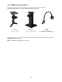
11.0 Optional accessories
These accessory items, purchased separately, will accommodate your JET bench grinder.
Contact your dealer to order, or call JET at the phone number on the cover.
578172 578173 578100
Stand for Grinders Deluxe Stand for Grinders Flexible 3W LED Lamp
(includes two 1/4 x 3/8 mounting screws)
The following accessories are for using the Grinder with the JET #414800 (JDCS-505) Dust Collection Stand:
414825 Reducer, 3 in. to 2.5 in.
414811 0.6M Hose, Heat Resistant, ø2.5 x 24.4 in.

19
12.0 Troubleshooting IBGB series Sander/Grinder
12.1 General mechanical and electrical problems
Some corrections may require a qualified electrician.
Symptom Possible Cause Correction
Motor will not start. No incoming power. Verify that plug is properly inserted into
receptacle. If so, check main panel for
tripped breaker or blown fuse.
Non-variable speed models: Safety
key is missing.
Make sure safety key is inserted.
Wheel(s) cannot rotate because of
obstruction.
Unplug and turn wheel by hand to ensure
free movement. Restart.
Fuse blown or circuit breaker open. Re-set. May be too many machines on
one circuit.
Motor cord cut or abraded. Replace with new cord.
Plug on cord is faulty. Replace with new plug.
Low line voltage. Check power line for proper voltage.
Faulty switch. Replace switch.
Faulty capacitor. Replace capacitor.
Open circuit in motor or loose
connection.
Inspect all lead connections on motor for
loose or open connections.
Motor faulty. Have motor inspected.
Motor will not start;
fuses blow or circuit
breakers trip.
Too many electrical machines
running on same circuit.
Turn off other machines and try again.
Use dedicated circuit if necessary.
Incorrect fuse. Try time delay fuse, or go to circuit with
higher rated fuse or circuit breaker.
Wheel(s) cannot rotate because of
obstruction.
Unplug and turn wheel by hand to ensure
free movement. Clear any obstructions
and restart.
Undersized extension cord. Use correct size extension cord.
Short circuit in line cord or plug. Inspect cord or plug for damaged
insulation and shorted wires.
Short circuit in motor or loose
connections.
Inspect all connections on motor for loose
or shorted terminals or worn insulation.
Motor fails to develop
full power.
Low line voltage. Check power line for proper voltage.
Faulty motor or capacitor. Contact JET technical service.
Motor overheats. Motor overloaded. Reduce pressure against wheel or platen.
Make sure grit size is appropriate for the
job.
Motor stalls, resulting
in blown fuses or
tripped breaker.
Motor overloaded. Reduce load on motor; do not press so
hard.
Capacitor failure. Contact JET technical service.
Short circuit in motor or loose
connections.
Inspect connections on motor for loose or
shorted terminals or worn insulation.

20
Symptom Possible Cause Correction
Motor stalls (cont.)
Low voltage. Correct the low voltage conditions.
Incorrect fuses or circuit breakers in
power line.
Install correct fuses or circuit breakers.
Motor slows. Motor overloaded. Reduce load to motor; do not press so
hard.
Low line voltage. Check power line for proper voltage.
Loose connections. Inspect connections.
Frequent fuse or circuit
breaker failure.
Motor overload. Reduce load to motor; do not press so
hard.
Electrical circuit overload; too many
electrical machines running on same
circuit.
Turn off other machines and try again.
Incorrect fuse or circuit breaker. Have electrician upgrade service to outlet.
Excessive vibration. Wheel out of balance; wobbling or
not rotating concentric to arbor.
Dress wheel or replace it. Adjust wobble
by rotating flange as needed.
Improper mounting. Secure grinder/sander firmly to bench or
stand.
Sanding belt will not
tension or de-tension
properly.
Tension rod is “sticking”; movement
obstructed.
Clean any debris from tension rod and
spring area. Lubricate spring if needed.
Spring is worn or damaged. Replace spring.
Set screw which holds tension rod to
wheel carrier is loose.
Tighten set screw.
Table 3
12.2 Digital readout error codes (Variable speed models)
Message Possible Cause Correction *
OCL Internal electronic overload has been tripped.
Do not overload motor; reduce pressure of
workpiece against wheels.
OH IGBT protection activated.
Inspect wire connections to U/V/W for possible
short circuits. Verify that motor rating
corresponds to AC motor drive output power.
OE
Excessive input voltage (exceeds AC driver
limits).
Use correct voltage.
LE1
Low voltage; AC motor driver detects that DC
bus voltage has fallen below minimum
threshold
Make sure input voltage falls within range of AC
motor input voltage range. Check for abnormal
load in motor.
LP1 Low input voltage (below AC driver limits) Use correct voltage.
Table 4
Page is loading ...
Page is loading ...
Page is loading ...
Page is loading ...
Page is loading ...
Page is loading ...
Page is loading ...
Page is loading ...
Page is loading ...
Page is loading ...
Page is loading ...
Page is loading ...
Page is loading ...
Page is loading ...
Page is loading ...
Page is loading ...
-
 1
1
-
 2
2
-
 3
3
-
 4
4
-
 5
5
-
 6
6
-
 7
7
-
 8
8
-
 9
9
-
 10
10
-
 11
11
-
 12
12
-
 13
13
-
 14
14
-
 15
15
-
 16
16
-
 17
17
-
 18
18
-
 19
19
-
 20
20
-
 21
21
-
 22
22
-
 23
23
-
 24
24
-
 25
25
-
 26
26
-
 27
27
-
 28
28
-
 29
29
-
 30
30
-
 31
31
-
 32
32
-
 33
33
-
 34
34
-
 35
35
-
 36
36


Ask a question and I''ll find the answer in the document
Finding information in a document is now easier with AI
Related papers
-
JET JWBG-8NW Owner's manual
-
JET IBDG-248VS Owner's manual
-
-
-
-
-
-
Unbranded 577102 User manual
-
-
Other documents
-
Ryobi 40 Volt Power Source RYi300BG Owner's manual
-
Rikon Power Tools 25-905 Owner's manual
-
Grizzly T28523 Owner's manual
-
HQ W7-60461-BLN Datasheet
-
Craftex CX Series CX911 Owner's manual
-
Ryobi RBGL650G Instructions Manual
-
General International 15-625 User guide
-
-
-
Panasonic 3343109 User manual