Danfoss Controller type AKC 114, 115, and 116 for controlling evaporators. Vers. 1.5x. AKA 21 Installation guide
- Category
- Thermostats
- Type
- Installation guide

RC.1H.V1.02 → RC.1H.V2.02 11-1998
Menu operation via AKA 21
Software version 1.5x
Controller for controlling evaporators
AKC 114, 115 and 116
ADAP-KOOL
®

2 Menu operation RC.1H.V2.02 © Danfoss 11/1998 AKC 114-116 Version 1.5x
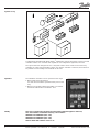
System survey
A refrigerating plant fitted with ADAP-KOOL
®
refrigeration controls will mostly consist of several
controllers where each controller will regulate its own refrigeration appliance/cold room.
The system has been designed in such a way that contact can be made to each and every
controller via a data communication system. One specific controller is selected, and it will now
be possible to make settings and readouts for this unit.
The individual controllers can be operated in two ways:
1. With control panel type AKA 21.
Use this document when operation takes place in this
way.
2. With PC and system software type AKM. Use another
document with literature number RC.1H.X.
Operation
Validity
This menu operation was worked out in November 1998 and applies to AKC 114,
AKC 115 and AKC 116 with the following code numbers:
084B6027 and 084B6026 (AKC 114)
084B6042 and 084B6046 (AKC 115)
084B6043 and 084B6047 (AKC 116)
that are fitted with software version 1.5x.

AKC 114-116 Version 1.5x Menu operation RC.1H.V2.02 © Danfoss 11/1998 3
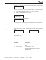
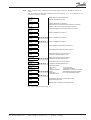
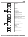
All controllers that are connected to the same network can be operated with the control panel.
There may be as many as 125 controllers, and they are shown in groups of 16 on the display.
A system is shown here which consists of more than 16 controllers. The meaning of the letters
is, as follows:
A: AKC controller
E: Controller with active ERROR (on addresses 2, 11 and 12 in this example)
g: Gateway (to addresses 13 and 14 in this example)
G: Gateway with connected printer
: A blank field indicates that there is no unit with this address.
Select the unit that is to be operated by using the “+/On” or “-/Off” key, and push “Enter”. In this
example you select the controller with address 4.
If the system comprises more than 16 units or units with an address code higher than 16, you
may change to the next group by pushing “→”.
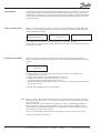
When a controller has been selected, you can make settings in it. This setting is performed, as
follows:
Shown in the upper right corner of the display is the setting with which the controller is
operating. Below that value a new setting may be made. Use the three keys “+/ON”,
“-/OFF” and “Digit” for setting the new value. This new value will not govern the regulation until
you push the key “Enter”.
Select a controller
Settings of a controller
5
-50 to +50 5
ON
OFF / ON ON
The functions in the controller can be protected by means of an access code. Depending on
the settings to be made, you may gain access in one of the following ways:
User input: Gives access to:
1. Push F1 Display of alarms
2. Push F2 Reading of selected temperatures, change of
temperature in the refrigeration appliance, start of
defrost
3. Code 1 and then F1 Acknowledgement of alarms
Code 1 and then F3 Setting of selected parameters
4. Code 2 Operation of all settings of the entire menu system
(with system software type AKM there is access to
additional functions).
Pages 6 and 7 contain a description of how you gain access to the system via a code.
Access to a controller
1 < 1 > 16
AEAAAAAAAAEEgg A
1 < 4 > 16
AEAAAAAAAAEEgg A
17 < 17 > 32
AAA

4 Menu operation RC.1H.V2.02 © Danfoss 11/1998 AKC 114-116 Version 1.5x
A supporting text is attached to the individual functions. When such a function is shown in the
control panel’s display, the supporting text can be obtained by pushing the key “Help”. The
supporting text is intended as a help to users who no longer use these operating instructions.
In the menus shown below functions with supporting texts are identified with the word “Help”
next to the function.
When an error appears in a system, it can be seen on the control panel’s display which will
show an “E”. If the control panel shows a text from a selected controller, the LED at the word
“Alarm” will furthermore flash.
When an error has occurred, first select the controller on which the error is registered. When
the controller has been found, push “F1”, and the error message will appear.
At the end of the document there is a list of all the error messages and a description of how to
acknowledge an alarm.
Supporting text
How to localise an error
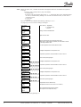
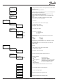
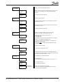
When one controller has been selected from the total system, the following display will
appear (the display is the first one shown when you have selected an address from the total
system):
e.g.
AKC 116 Adr: 2
E Mon-11:27
From this position you can freely choose between several forms of operating levels:
1. Display of alarms - push “F1”
2. Display and setting of a few selected functions - push “F2”
3. Display and setting of several selected functions - push “F3”
The function may be protected with a code (code 1)
4. Display and setting of all allowed functions in the controller. The function may be protected
with a code (code 2).
Operation of the individual levels is shown below:
When you push “F1” the alarm messages from the controller in question appear. Only active
alarms are shown. With a push on “↓” you can see whether there are more alarm messages,
and if so, their texts.
When an alarm has been localised and corrected, the alarm is acknowledged (removed
from the system, so that it no longer appears). In large systems where a gateway is also
connected this acknowledgement will take place automatically. In other systems it has to be
done manually, cf. end of the document.
Prior to the acknowledgement of the alarm, the keying of a code is required, see page 6.
Leave the F1 function by pushing “←”.
Functions of a controller
1 < 2 > 16
AEAAAAAAAAAAgg A
AKC 116 Adr: 2
E Mon-11:27
High air temp
1. F1

AKC 114-116 Version 1.5x Menu operation RC.1H.V2.02 © Danfoss 11/1998 5
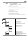
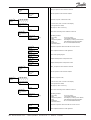
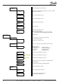
When you push “F2” a number of functions will appear where it is possible to read or set
values.
You can move to and from the individual functions by pushing “↑” or “↓”. On page 3 you can
see how a setting is changed.
Man. Def. Manual defrost is activated when ON
OFF/ON (changes automatically to OFF)
7:03:02
|
CutOut °C Setting of thermostat cut-out value
-50 - 50 MUST BE SET. Even if the thermostat function has not been
6:03:03 selected. (The value is used by the injection function).
|
AlarmAir A Actual air temperature for the alarm function in section A
6:02:01
|
Ther.Air A Actual air temperature (section A)
6:02:02
|
Air Temp B Only AKC 115/116 Actual air temperature (section B)
6:02:03
|
Air Temp C Only AKC 116 Actual air temperature (section C)
6:02:04
|
S3 °C (A) Air temperature at evaporator inlet (section A)
6:02:05
|
S4 °C (A) Air temperature at evaporator outlet (section A)
6:02:06
|
RunTime A Actual thermostat cut-in time of section A
6:02:09 or duration of the latest finished cut-in
|
RunTime B Actual thermostat cut-in time of section B
6:02:10 Only AKC 115/116 or duration of the latest finished cut-in
|
RunTime C Actual thermostat cut-in time of section C
6:02:11 Only AKC 116 or duration of the latest finished cut-in
|
Reg Cond. A Regulating condition
3:02:01 0: No cooling 6: Forced closing
| 1: Start 7: Regulation problems
Reg Cond. B 2: Adaptive regulation 8: Emergency cooling (sensor failure)
4:02:01 Only AKC 115/116 3: Start 9: Modulating thermostat regulation
| 4: Defrosting 10: Forced cutout(Melt function)
Reg Cond. C 5: Start after defrost
5:02:01 Only AKC 116
|
DefTime m Actual defrost cut-in time or duration of the latest
7:02:05 finished defrosting period.
|
MDefTime m Average value of the latest 4 defrosting periods.
7:02:06
Leave the F2 function by pushing “←”.
2. F2

6 Menu operation RC.1H.V2.02 © Danfoss 11/1998 AKC 114-116 Version 1.5x
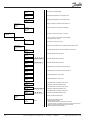
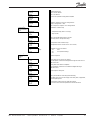
When you push “F3”, a number of functions will appear which are used when the system is
serviced.
• If access code is used (code 1), key it as follows:
- Push the “key”
- Enter the code by using the three keys “+”, “-” and “Digit” (the code is mentioned later
as code 1, and the factory setting is 40. If code 2 has been set at 0, access code 1
cannot be used).
- Push “Enter”
- Push “F3”
Move to and from the individual functions by pushing “↑” or “↓”.
On page 3 you can see how a setting is changed.
Main Switch Main switch: 1: Regulation
-1 / 0 / 1 0: Controller stop
2:02:01 -1: Service
|
Diff. K Setting of thermostat differential
0.5 - 10
6:03:04
|
Dt Night K Night set back value
-25 - 25
6:04:02
|
High Lim °C High air temperature alarm limit (absolute value).
-50 - 50 When there is night setback operation, the alarm limit is raised
6:05:02 by the night setback value.
|
Low Lim °C Low air temperature alarm limit (absolute value)
-50 - 50
6:05:05
|
S1 °C (A) Refrigerant temperature at evaporator inlet.
3:02:05
|
S2-S1 K A Evaporator superheat measured with S1 and S2 sensors
3:02:02
|
AKV OD % A Actual valve opening degree
3:02:04
|
S1 °C (B) Refrigerant temperature at evaporator inlet.
4:02:05 Only AKC 115/116
|
S2-S1 K B Evaporator superheat measured with S1 and S2 sensors
4:02:02 Only AKC 115/116
AKV OD % B Actual valve opening degree
4:02:04 Only AKC 115/116
|
S1 °C (C) Refrigerant temperature at evaporator inlet.
5:02:05 Only AKC 116
|
S2-S1 K C Evaporator superheat measured with S1 and S2 sensors
5:02:02 Only AKC 116
|
AKV OD % C Actual valve opening degree
5:02:04 Only AKC 116
|
Def.Stop °C Temperature value of defrost stop
0 - 60 (Temperature at the chosen sensor. See 7:04:04)
7:04:03
|
MaxDefTime Max. permissible defrost time in minutes
5 - 180 (Security time on Temperature stop)
7:04:02
Leave the function by pushing “←”.
3. F3

AKC 114-116 Version 1.5x Menu operation RC.1H.V2.02 © Danfoss 11/1998 7
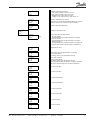
4. Access to all
functions
The access to the functions may be protected with a code (code 2).
• If access code is used, key it as follows:
- Push the “key”
- Enter the code by using the three keys “+”, “-” and “Digit”
- Push “Enter”
- Push “←”
Move to and from the individual functions by pushing the four arrow keys.
On page 3 you can see how a setting is changed.
When you wish to leave the “Access to all functions” function, push “Clear” and then “←”.
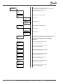
List of functions on level 1:
1. Controller’s access display and access to system information
2. Interruption of regulation and selection of language
3. Injection function for section A
4. Injection function for section B (AKC 115/116 only)
5. Injection function for section C (AKC 116 only)
6. Thermostat function, night-setback function, alarm function, fan control and rail heat control
7. Defrost function
8. Forced control functions for service and initial setting
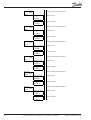
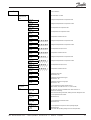
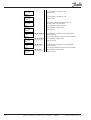
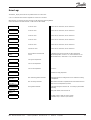
Below and on the following pages the individual functions are shown together with a brief
description:
Level 1 Level 2 Level 3 Level 4 Description
AKC 116 Adr: xxx Controller access display
Mon hh:mm If the code function is used, continue by pushing the "key" key.
Enter Code Entry of access code 1 or access code 2 (cf. also 1:07 and 1:08).
0 - 255 0 Continue by pushing "arrow left"
1:01
AKC 116 Adr: xxx Access to system information
Mon hh:mm If an E appears in the display, an error has been re
g
istered.
1
Code No. Readin
g
of the controller’s code no. and pro
g
ramme version.
Prog. Ver.
1:02
|
Clock: Settin
g
of controller clock (AKC clock)
Mon hh:mm
1:03
Clock: Day. Settin
g
of day (1 = Monday, 7 = Sunday)
Mon(1) Sun(7)
1:03:01
|
Clock: Hour Settin
g
of hours
0 - 23
1:03:02
|
Clock: Min. Settin
g
of minutes
0 - 59
1:03:03
|
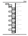
System Address Readin
g
of the controller’s system address
Addr. yyy xxx yyy=network no. and xxx=address.
1:04 The system address can only be set via PC
|
Alarm report to Readin
g
of the alarm address (end receiver) the alarms are to be
Addr. yyy xxx sent to.
1:05 The alarm address can only be set via PC.

8 Menu operation RC.1H.V2.02 © Danfoss 11/1998 AKC 114-116 Version 1.5x
|
Gateway Address Reading of the address on the nearst gateway which has to effect
xxx alarms (see 1:05)
1:06 The address can only be set via PC
|
Ch
g
. Code1 Chan
g
e of code 1. The code
g
ives access to acknowled
g
ement of
0 - 255 active alarm by means of the F1 key.
1:07 Also access to the selected settin
g
s/readouts via the F3 key.
| (Factory settin
g
= 40) (See also code 2)
Ch
g
. Code2 Chan
g
e of code 2. The code
g
ives access to the whole menu
0 - 255 system.
1:08 (Factory settin
g
= 0. Settin
g
= 0 offers free access where
neither code 1 not code 2 is required)
|
Main Function Main function
2
Alarm Messa
g
e(s) In case of alarm, an E is shown on the display
2:01 (Error lo
g
becomes visible)
See pa
g
e 23, check of error lo
g
2:01:01
|
Main Function Access to the main switch
Settin
g
s
2:02
Main Switch Main switch: 1: Re
g
ulation
-1 / 0 / 1 Help 0: Controller stop
2:02:01 -1: Service
|
Lan
g
ua
g
e Selection of lan
g
ua
g
e. Three lan
g
ua
g
es have been entered
0 - 4 Help in the controller
2:02:02 Either: Or:
0: En
g
lish 0: En
g
lish
1: German 3: Danish
2: French 4: Spanish
NB! This function must be set prior to any uploadin
g
to system
software type AKM.
When the lan
g
ua
g
e code has been chan
g
ed, push "ENTER"
and then "Clear".
|
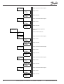
Injection (A) Section A
Control
3 In case of alarm, an E is shown on the display
Alarm messa
g
e(s) (Error lo
g
becomes visible)
3:01
See pa
g
e 23, check of error lo
g
3:01:01
|
Injection (A) Read-out of measurin
g
values related to section A
Measurements
3:02
Re
g
Cond. A Re
g
ulatin
g
condition
3:02:01 Help 0: No coolin
g
6: Forced closin
g
1: Start 7: Re
g
ulation problems
2: Adaptive re
g
ulation 8: Emer
g
ency coolin
g
(sensor failure)
3: Start 9: Modulatin
g
thermostat re
g
ulation
4: Defrostin
g
10: Forced cutout(Melt function)
5: Start after defrost
|
S2-S1 K A Evaporator superheat measured with S1 and S2 sensors
3:02:02
|
SH Ref K A Actual superheat reference of the re
g
ulation
3:02:03
|
AKV OD % A Actual valve openin
g
de
g
ree
3:02:04
|
S1 °C (A) Refri
g
erant temperature at evaporator inlet.
3:02:05
|
S2 °C (A) Refri
g
erant temperature at evaporator outlet.
3:02:06

AKC 114-116 Version 1.5x Menu operation RC.1H.V2.02 © Danfoss 11/1998 9
|
Injection (A) Setting of expansion valve function section A
Settin
g
3:03
In
j
. Ctrl. A Choose expansion valve function ON/OFF
OFF / ON
3:03:01
|
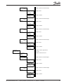
In
j
ection (B) Onl
y
AKC 115/116 Section B (onl
y
AKC 115 and AKC 116)
Control
4
Alarm messa
g
e In case of alarm, an E is shown on the displa
y
4:01 (Error log becomes visible)
See page 23, check of error log
4:01:01
|
Injection (B) Read-out of measuring values related to section B
Measurements
4:02
Re
g
Cond. B Re
g
ulatin
g
condition
4:02:01 Help 0: No coolin
g
6: Forced closin
g
1: Start 7: Regulation problems
2: Adaptive re
g
ulation 8: Emer
g
enc
y
coolin
g
(sensor failure)
3: Start 9: Modulating thermostat regulation
4: Defrostin
g
10: Forced cutout(Melt function)
5: Start after defrost
|
S2-S1 K B Evaporator superheat measured with S1 and S2 sensors
4:02:02
|
SH Ref K B Actual superheat reference of the re
g
ulation
4:02:03
|
AKV OD % B Actual valve opening degree
4:02:04
|
S1 °C (B) Refrigerant temperature at evaporator inlet.
4:02:05
|
S2 °C (B) Refrigerant temperature at evaporator outlet.
4:02:06
|
In
j
ection (B) Settin
g
of expansion valve funciton section B
Setting
4:03
In
j
. Ctrl. B Choose expansion valve function ON/OFF
OFF / ON
4:03:01
|
In
j
ection (C) Onl
y
AKC 116 Section C (onl
y
AKC 116)
Control
5
Alarm message(s) In case of alarm, an E is shown on the display
5:01 (Error lo
g
becomes visible)
See page 23, check of error log
5:01:01
|
In
j
ection (C) Read-out of measurin
g
values related to section C
Measurements
5:02
Re
g
Cond. C Re
g
ulatin
g
condition
5:02:01 Help 0: No cooling 6: Forced closing
1: Start 7: Re
g
ulation problems
2: Adaptive regulation 8: Emergency cooling (sensor failure)
3: Start 9: Modulating thermostat regulation
4: Defrostin
g
10: Forced cutout(Melt function)
5: Start after defrost
|
S2-S1 K C Evaporator superheat measured with S1 and S2 sensors
5:02:02
|
SH Ref K C Actual superheat reference of the regulation
5:02:03

10 Menu operation RC.1H.V2.02 © Danfoss 11/1998 AKC 114-116 Version 1.5x
|
AKV OD % C Actual valve openin
g
de
g
ree
5:02:04
|
S1 °C (C) Refri
g
erant temperature at evaporator inlet.
5:02:05
|
S2 °C (C) Refrigerant temperature at evaporator outlet.
5:02:06
|
Injection (C) Settin
g
of expansion valve funciton section C
Settin
g
5:03
Inj. Ctrl C Choose expansion valve function ON/OFF
OFF / ON
5:03:01
|
Common Functions common to sections A, B and C
Controller
6
Alarm messa
g
e(s) In case of alarm, an E is shown on the display
6:01 (Error lo
g
becomes visible)
See pa
g
e 23, check of error lo
g
6:01:01
|
Thermostat Read.out of measurin
g
values related to thermostat function.
Measurements
6:02
AlarmAir A Actual air temperature for the alarm function in section A
6:02:01
|
Ther.Air A Actual air temperature (section A)
6:02:02
|
Air Temp B Only AKC 115/116 Actual air temperature (section B)
6:02:03
|
Air Temp C Only AKC 116 Actual air temperature (section C)
6:02:04
|
S3 °C (A) Air temperature at evaporator inlet (section A)
6:02:05
|
S4 °C (A) Air temperature at evaporator outlet (section A)
6:02:06
|
CutOut °C Actual thermostat(s) cut-out value
6:02:07
|
CutIn °C Actual thermostat(s) cut-in value
6:02:08
|
RunTime A Actual thermostat cut-in time of section A
6:02:09 or duration of the latest finished cut-in
|
RunTime B Actual thermostat cut-in time of section B
6:02:10 Only AKC 115/116 or duration of the latest finished cut-in
|
RunTime C Actual thermostat cut-in time of section C
6:02:11 Only AKC 116 or duration of the latest finished cut-in
|
Thermostat Ctrl. Settin
g
s for thermostat function
Settin
g
s
6:03
Ther. Mode Definition of thermostat function
0 - 3 Help 0: No thermostat function
6:03:01 1: The thermostat function is atached to section A
(cutout and cutin of sections B and C will come after section A)
2: There is one thermostat function in each function
3: Modulatin
g
thermostat re
g
ulation

AKC 114-116 Version 1.5x Menu operation RC.1H.V2.02 © Danfoss 11/1998 11
|
Ther. Sx Definition of thermostat sensor(s)
1 - 3 1: S3A, S3/4B and S3/4C sensor(s) is used
6:03:02 2: S4A, S3/4B and S3/4C sensor(s) is used
3: Wei
g
hted value of S3A and S4A is used
(settin
g
= 3 may only be used, if "Ther. Mode" = 1)
|
CutOut °C Settin
g
of thermostat cut-out value
-50 - 50 MUST BE SET. Even if the thermostat function has not been
6:03:03 selected. (The value is used by the injection function).
|
Diff. K Settin
g
of thermostat differential
0.5 - 10
6:03:04
|
Day/Ni
g
ht Ctrl. Settin
g
s of day/ni
g
ht function
Settin
g
s
6:04
Day/Ni
g
ht Choose day-/ni
g
ht operation function
0 3 Help 0: No ni
g
ht setback
6:04:01 1: Chan
g
e between day and ni
g
ht operation accordin
g
to
si
g
nal on S6 input
2: Chan
g
e between day and ni
g
ht operation accordin
g
to
internal time clock
3: Chan
g
e between day and ni
g
ht operation accordin
g
to the
si
g
nal from the master controller (Si
g
nal via DANBUSS)
|
Dt Ni
g
ht K Ni
g
ht set back value
-25 - 25
6:04:02
Mo day h Time table for day and ni
g
ht operation on Mondays
0 24 End of ni
g
ht setback
6:04:03 At settin
g
= 0 there is no ni
g
ht setback this day
|
Mo ni
g
ht h Time table continued:
0 24 Start (of ni
g
ht setback)
6:04:04 At settin
g
= 0 there is no displacement this day
If day and night settings are identical, or if night is set before
the function will be chan
g
ed. See functional description
|
Tu day h As above, Tuesdays
0 24
6:04:05
|
Tu ni
g
ht h As above, Tuesdays
0 24
6:04:06
|
We day h As above, Wednesdays
0 24
6:04:07
|
We ni
g
ht h As above, Wednesdays
0 24
6:04:08
|
Th day h As above, Thursdays
0 24
6:04:09
|
Th ni
g
ht h As above, Thursdays
0 24
6:04:10
|
Fr day h As above, Fridays
0 24
6:04:11
|
Fr ni
g
ht h As above, Fridays
0 24
6:04:12

12 Menu operation RC.1H.V2.02 © Danfoss 11/1998 AKC 114-116 Version 1.5x
|
Sa day h As above, Saturdays
0 24
6:04:13
|
Sa ni
g
ht h As above, Saturdays
0 24
6:04:14
|
Su day h As above, Sundays
0 24
6:04:15
|
Su ni
g
ht h As above, Sundays
0 24
6:04:16
|
Air Temp. Alarm Settin
g
s for alarm function
Settin
g
s
6:05
Alarm Mode Definition of alarm thermostat
0 - 3 Help 0: No alarm thermostat
6:05:01 1: S3A, S3/4B and S3/4C used as alarm sensors
2: S4A, S3/4B and S3/4C used as alarm sensors
3: (Only AKC 114) Thermostat temperature in section A is
used (see 6:02:02 TherAir A).
|
Hi
g
h Lim °C Hi
g
h air temperature alarm limit (absolute value).
-50 - 50 When there is ni
g
ht setback operation, the alarm limit is raised
6:05:02 by the ni
g
ht setback value.
|
Hi
g
h1Del m Time delay of hi
g
h air temperature alarm durin
g
pull-down.
0 - 240 Help This value will apply until the actual air temperature has dropped
6:05:03 below the "upper alarm limit".
Thereafter shift to the time delay "Hi
g
h2Del m".
|
Hi
g
h2Del m Time delay of hi
g
h air temperature alarm durin
g
normal re
g
ulation.
0 - 60 Help
6:05:04
|
Low Lim °C Low air temperature alarm limit (absolute value)
-50 - 50
6:05:05
|
Low Del m Time delay for low air temperature alarm
0 - 60
6:05:06
|
Display Settin
g
Settin
g
s for external temperature display type AKA 14
6:06
Disp. ctrl. Choose read-out for display
0 - 3 Help 0: No display function
6:06:01 1: S3 read out
2: S4 read out
3: Ther.Air read out
|
Offset K A Offset adjustment of display si
g
nal, display A
-10.0 10.0
6:06:02
|
Offset K B Offset adjustment of display si
g
nal, display B
-10.0 10.0
6:06:03
|
Offset K C Offset adjustment of display si
g
nal, display C
-10.0 10.0
6:06:04

AKC 114-116 Version 1.5x Menu operation RC.1H.V2.02 © Danfoss 11/1998 13
|
Fan Pulsin
g
Settin
g
of fan pulsin
g
durin
g
ni
g
ht operation
(CutOut Ni
g
ht)
6:07
Fan On % Settin
g
of the fans’ ON period in percent of the "FanCycl m" time
0 - 100 (the function is only active in the cutout period durin
g
ni
g
ht
6:07:01 operation).
|
FanCycl m Period time for total ON / OFF time
0.0 - 60.0
6:07:02
|
Railheat Pulsin
g
Settin
g
s for railheat function
(Day/Ni
g
ht)
6.08
RailOnDay % Durin
g
day operation: Settin
g
of rail heat ON period in percent
0 - 100 of the "RailCycl m" time.
6:08:01
|
RailOnN
g
t % Durin
g
ni
g
ht operation: Settin
g
of rail heat ON period in percent
0 - 100 of the "RailCycl m" time
6:08:02
|
RailCycl m Period time for total ON / OFF time
6 - 60
6:08:03
|
Output Ctrl. at Definition of controller outputs at forced control si
g
nal
Forced Closin
g
(when the "ON" inlet is cut-out (terminal 32 - 33))
6:09
Output Ctrl. Output functions when there is forced control
1 - 3 Help 1: Fan outlet is ON
6:09:01 2: Fan outlet is OFF
3: All outlets are OFF and alarm thermostat function is stopped.
|
ON-InpMode Definition of AKC-ON input (terminals 32-33)
0 - 1 0: Connection not used, as the re
g
ulation is controlled by the
6:09:02
g
ateway’s override function
1: Connection must
be made (when te volta
g
e is interrupted
the valve closes)
|
Safety Function Settin
g
s for fan stop function
Fan Stop by S5
6:10
FanStopS5 Fan stop function defines ON or OFF
OFF/ON Help
6:10:01
|
FanStop °C Temperature limit for fan stop (the fans are stopped when the
-50 - 50 S5A temperature is hi
g
her than this value. The fans will start a
g
ain
6:10:02 when S5A is lower than "FanStop °C" - 2K)
|
Extended Ther. Extended settin
g
s for thermostat function
Ctrl. Settin
g
s
6:11
S4 Day % S4 wei
g
htin
g
by day
0 - 100 S3 is automatically wei
g
hted. Must only be set if "Ther.Sx" = 3
6:11:01
|
S4 Ni
g
ht % S4 is wei
g
htin
g
at ni
g
ht
0 - 100 S3 is automatically wei
g
hted
6:11:02
|
S4MinLim °C Only AKC 114 Settin
g
of low S4 temperature alarm limit
-50 - 50 The function is only active, if wei
g
htin
g
between S3 and S4
6:11:03 Help is used for the thermostat function

14 Menu operation RC.1H.V2.02 © Danfoss 11/1998 AKC 114-116 Version 1.5x
|
Extended Inject. Extended settin
g
s for injection function
Ctrl. Settin
g
s
6:12
Glide K Temperature displacement for refri
g
erant is only set in systems
0.0 - 10.0 with zeotropic refri
g
erants.
6:12:01
|
SH Max K Max. superheat reference value
3.0 - 15.0
6:12:02
|
SH Min K Min. superheat reference value
3.0 - 10.0
6:12:03
|
MOP Ctrl. Choose MOP function ON/OFF
OFF/ON
6:12:04
|
MOP °C MOP point value
-50 - 15
6:12:05
|
TEV Define type of expansion valve
OFF/ON OFF: AKV valves are used
6:12:06 ON: Connect a solenoid valve (TEV) to the AKV output.
(Inj. Ctrl 3:03:01, 4:03:01 and 5:03:01 must be "Off")
|
Defrost Control Defrost function
7:00
Alarm messa
g
e(s) In case of alarm, an E is shown on the display
7:01 (Error lo
g
becomes visible)
See pa
g
e 23, check of error lo
g
7:01:01
|
Defrost Read-out of measurin
g
values related to defrost function
Measurements
7:02
Def. Cond. Defrost condition
7:02:01 Help 0: Defrost not started 4: Reserved delay 2
1: Pump down 5: Drainin
g
of evaporator
2: Extra delay 1 6: Delayed injection
3: Defrost 7: Delayed fan start
|
S5 °C (A) Defrost sensor temperature in section A
7:02:02
|
S5 °C (B) Only AKC 115/116 Defrost sensor temperature in section B
7:02:03
|
S5 °C (C) Only AKC 116 Defrost sensor temperature in section C
7:02:04
|
DefTime m Actual defrost cut-in time or duration of the latest finished
7:02:05 defrostin
g
period.
|
MDefTime m Avera
g
e value of the latest 4 defrostin
g
periods.
7:02:06 Help
|
Defrost Ctrl. Definition of defrostin
g
method
Settin
g
s
7:03
Def. Ctrl. Choose defrost function ON/OFF
OFF/ON
7:03:01
|
Man. Def. Manual defrost is activated when ON
OFF/ON (chan
g
es automatically to OFF)
7:03:02

AKC 114-116 Version 1.5x Menu operation RC.1H.V2.02 © Danfoss 11/1998 15
|
Hot
g
as Def. Define defrost form
OFF/ON OFF: Electric defrost
7:03:03 ON : Gas defrost
|
Fan Run Choose fan operation durin
g
defrost ON/OFF
OFF/ON
7:03:04
|
Compr. run Define if compressor must run durin
g
defrost.
OFF/ON (Only if "Hot
g
as Def" = ON)
7:03:05 ON: compressor output is cut-in durin
g
defrost
|
Defrost Stop. Definitions of defrost stop
Temp(1)/Time(2)
7:04
Temp/Time 1: Temperature stop (time as security)
1 - 2 2: Stop on time
7:04:01
|
MaxDefTime Max. permissible defrost time in minutes
5 - 180 (Security time on Temperature stop)
7:04:02
|
Def.Stop °C Temperature value of defrost stop
0 - 60 (Temperature at the chosen sensor. See 7:04:04)
7:04:03
|
DefStop Sx Definition of sensor for defrost
1 - 5 Help 1: S1 4:S4
7:04:04 2: S2 5: S5 (Normal settin
g
)
3: S3
|
Defrost Sequence Defrost sequence
Settin
g
s
7:05
PumpdDel m Delay time prior to start of
g
as defrost.
0 - 60 The evaporator is drained of refri
g
erant throu
g
h the main valve in
7:05:01 the suction line.
|
DrainDel m Delay time when defrost completed
0 - 60 The evaporator is drained of condensed refri
g
erant throu
g
h
7:05:02 the drain valve.
|
Inj.Del m Liquid injection delay time
0 - 60
7:05:03
|
FanOnDel m Max. permissible fan start delay after defrostin
g
.
0 - 60 The delay time runs from the expiry of the delay time, if applicable,
7:05:04 for the liquid injection.
|
Fan On °C Temperature at which the fan starts after defrost.
-15 - 0 Fans starts when all S5 temperatures are below the value.
7:05:05

16 Menu operation RC.1H.V2.02 © Danfoss 11/1998 AKC 114-116 Version 1.5x
|
Extended Pro
g
ram Help function for settin
g
of defrost times
Schedules The defrost periods are distributed evenly durin
g
a defined
7:06 period of time within a 24-hour period.
No. Per Day Number of defrosts/24 hours
2 - 8
7:06:01
|
FirstDef Setting of time the 1st defrost begins
00:00
7:06:02
FirstDef Hour Setting of hours
0 - 23
07.06.02.01
|
FirstDef Min. Settin
g
of minutes
0 - 59
07.06.02.02
|
LastDef Settin
g
of time the last defrost be
g
ins
00:00
7:06:03
LastDef Hour Settin
g
of hours
0 - 23
07.06.03.01
|
LastDef Min. Settin
g
of minutes
0 - 59
07.06.03.02
|
Auto Set Transfer the values to the three subsequent defrost pro
g
rammes.
OFF/ON Help In pos. ON they are entered in "7:07", "7:08" and "7:09".
7:06:04 If the three defrost pro
g
rammes are not to be identical,
corrections subsequent must be made in the individual
pro
g
rammes.
|
Mon Sched. Choose defrost pro
g
ramme for Mondays
1 - 3 See also 7:07, 7:08 and 7:09
7:06:05
|
Tue Sched. Choose defrost pro
g
ramme for Tuesdays
1 - 3 See also 7:07, 7:08 and 7:09
7:06:06
|
Wed Sched. Choose defrost pro
g
ramme for Wednesdays
1 - 3 See also 7:07, 7:08 and 7:09
7:06:07
|
Thu Sched. Choose defrost pro
g
ramme for Thursdays
1 - 3 See also 7:07, 7:08 and 7:09
7:06:08
|
Fri Sched. Choose defrost pro
g
ramme for Fridays
1 - 3 See also 7:07, 7:08 and 7:09
7:06:09
|
Sat Sched. Choose defrost pro
g
ramme for Saturdays
1 - 3 See also 7:07, 7:08 and 7:09
7:06:10
|
Sun Sched. Choose defrost pro
g
ramme for Sundays
1 - 3 See also 7:07, 7:08 and 7:09
7:06:11

AKC 114-116 Version 1.5x Menu operation RC.1H.V2.02 © Danfoss 11/1998 17
|
Schedule 1 Settin
g
s for defrost pro
g
ramme 1
Def. Start Times See 07:06
7:07
No. Per Day Number of defrosts/24 hours
0 - 8
7:07:01
|
Def1 Sc1 Setting of time the 1st defrost begins
00:00
7:07:02
Def1 Sc1 Hour Settin
g
of hours
0 - 23
07:07:02:01
|
Def1 Sc1 Min. Settin
g
of minutes
0 - 59
07:07:02:02
|
Def2 Sc1 Settin
g
of time the 2nd defrost be
g
ins
00:00
7:07:03
Def2 Sc1 Hour Settin
g
of hours
0 - 23
07:07:03:01
|
Def2 Sc1 Min. Settin
g
of minutes
0 - 59
07:07:03:02
|
Def3 Sc1 Settin
g
of time the 3rd defrost be
g
ins
00:00
7:07:04
Def3 Sc1 Hour Settin
g
of hours
0 - 23
07:07:04:01
|
Def3 Sc1 Min. Settin
g
of minutes
0 - 59
07:07:04:02
|
Def4 Sc1 Settin
g
of time the 4th defrost be
g
ins
00:00
7:07:05
Def4 Sc1 Hour Settin
g
of hours
0 - 23
07:07:05:01
|
Def4 Sc1 Min. Settin
g
of minutes
0 - 59
07:07:05:02
|
Def5 Sc1 Settin
g
of time the 5th defrost be
g
ins
00:00
7:07:06
Def5 Sc1 Hour Settin
g
of hours
0 - 23
07:07:06:01
|
Def5 Sc1 Min. Settin
g
of minutes
0 - 59
07:07:06:02
|
Def6 Sc1 Settin
g
of time the 6th defrost be
g
ins
00:00
7:07:07
Def6 Sc1 Hour Settin
g
of hours
0 - 23
07:07:07:01
|
Def6 Sc1 Min. Settin
g
of minutes
0 - 59
07:07:07:02

18 Menu operation RC.1H.V2.02 © Danfoss 11/1998 AKC 114-116 Version 1.5x
|
Def7 Sc1 Settin
g
of time the 7th defrost be
g
ins
00:00
7:07:08
Def7 Sc1 Hour Settin
g
of hours
0 - 23
07:07:08:01
|
Def7 Sc1 Min. Settin
g
of minutes
0 - 59
07:07:08:02
|
Def8 Sc1 Settin
g
of time the 8th defrost be
g
ins
00:00
7:07:09
Def8 Sc1 Hour Settin
g
of hours
0 - 23
07:07:09:01
|
Def8 Sc1 Min. Settin
g
of minutes
0 - 59
07:07:09:02
|
Schedule 2 Settin
g
s for defrost pro
g
ramme 2
Def. Start Times See 07:06
7:08
No. Per Day Number of defrosts/24 hours
0 - 8
7:08:01
|
Def1 Sc2 Settin
g
of time the 1st defrost be
g
ins
00:00
7:08:02
Def1 Sc2 Hour Settin
g
of hours
0 - 23
07:08:02:01
|
Def1 Sc2 Min. Settin
g
of minutes
0 - 59
07:08:02:02
|
Def2 Sc2 Settin
g
of time the 2nd defrost be
g
ins
00:00
7:08:03
Def2 Sc2 Hour Settin
g
of hours
0 - 23
07:08:03:01
|
Def2 Sc2 Min. Settin
g
of minutes
0 - 59
07:08:03:02
|
Def3 Sc2 Settin
g
of time the 3rd defrost be
g
ins
00:00
7:08:04
Def3 Sc2 Hour Settin
g
of hours
0 - 23
07:08:04:01
|
Def3 Sc2 Min. Settin
g
of minutes
0 - 59
07:08:04:02
|
Def4 Sc2 Settin
g
of time the 4th defrost be
g
ins
00:00
7:08:05
Def4 Sc2 Hour Settin
g
of hours
0 - 23
07:08:05:01
|
Def4 Sc2 Min. Settin
g
of minutes
0 - 59
07:08:05:02

AKC 114-116 Version 1.5x Menu operation RC.1H.V2.02 © Danfoss 11/1998 19
|
Def5 Sc2 Settin
g
of time the 5th defrost be
g
ins
00:00
7:08:06
Def5 Sc2 Hour Settin
g
of hours
0 - 23
07:08:06:01
|
Def5 Sc2 Min. Settin
g
of minutes
0 - 59
07:08:06:02
|
Def6 Sc2 Settin
g
of time the 6th defrost be
g
ins
00:00
7:08:07
Def6 Sc2 Hour Settin
g
of hours
0 - 23
07:08:07:01
|
Def6 Sc2 Min. Settin
g
of minutes
0 - 59
07:08:07:02
|
Def7 Sc2 Settin
g
of time the 7th defrost be
g
ins
00:00
7:08:08
Def7 Sc2 Hour Settin
g
of hours
0 - 23
07:08:08:01
|
Def7 Sc2 Min. Settin
g
of minutes
0 - 59
07:08:08:02
|
Def8 Sc2 Settin
g
of time the 8th defrost be
g
ins
00:00
7:08:09
Def8 Sc2 Hour Settin
g
of hours
0 - 23
07:08:09:01
|
Def8 Sc2 Min. Settin
g
of minutes
0 - 59
07:08:09:02
|
Schedule 3 Settin
g
s for defrost pro
g
ramme 3
Def. Start Times See 7:06
7:09
No. Per Day Number of defrosts/24 hours
0 - 8
7:09:01
|
Def1 Sc3 Settin
g
of time the 1st defrost be
g
ins
00:00
7:09:02
Def1 Sc3 Hour Settin
g
of hours
0 - 23
07:09:02:01
|
Def1 Sc3 Min. Settin
g
of minutes
0 - 59
07:09:02:02
|
Def2 Sc3 Settin
g
of time the 2nd defrost be
g
ins
00:00
7:09:03
Def2 Sc3 Hour Settin
g
of hours
0 - 23
07:09:03:01
|
Def2 Sc3 Min. Settin
g
of minutes
0 - 59
07:09:03:02

20 Menu operation RC.1H.V2.02 © Danfoss 11/1998 AKC 114-116 Version 1.5x
|
Def3 Sc3 Settin
g
of time the 3rd defrost be
g
ins
00:00
7:09:04
Def3 Sc3 Hour Settin
g
of hours
0 - 23
07:09:04:01
|
Def3 Sc3 Min. Settin
g
of minutes
0 - 59
07:09:04:02
|
Def4 Sc3 Settin
g
of time the 4th defrost be
g
ins
00:00
7:09:05
Def4 Sc3 Hour Settin
g
of hours
0 - 23
07:09:05:01
|
Def4 Sc3 Min. Settin
g
of minutes
0 - 59
07:09:05:02
|
Def5 Sc3 Settin
g
of time the 5th defrost be
g
ins
00:00
7:09:06
Def5 Sc3 Hour Settin
g
of hours
0 - 23
07:09:06:01
|
Def5 Sc3 Min. Settin
g
of minutes
0 - 59
07:09:06:02
|
Def6 Sc3 Settin
g
of time the 6th defrost be
g
ins
00:00
7:09:07
Def6 Sc3 Hour Settin
g
of hours
0 - 23
07:09:07:01
|
Def6 Sc3 Min. Settin
g
of minutes
0 - 59
07:09:07:02
|
Def7 Sc3 Settin
g
of time the 7th defrost be
g
ins
00:00
7:09:08
Def7 Sc3 Hour Settin
g
of hours
0 - 23
07:09:08:01
|
Def7 Sc3 Min. Settin
g
of minutes
0 - 59
07:09:08:02
|
Def8 Sc3 Settin
g
of time the 8th defrost be
g
ins
00:00
7:09:09
Def8 Sc3 Hour Settin
g
of hours
0 - 23
07:09:09:01
|
Def8 Sc3 Min. Settin
g
of minutes
0 - 59
07:09:09:02
Page is loading ...
Page is loading ...
Page is loading ...
Page is loading ...
-
 1
1
-
 2
2
-
 3
3
-
 4
4
-
 5
5
-
 6
6
-
 7
7
-
 8
8
-
 9
9
-
 10
10
-
 11
11
-
 12
12
-
 13
13
-
 14
14
-
 15
15
-
 16
16
-
 17
17
-
 18
18
-
 19
19
-
 20
20
-
 21
21
-
 22
22
-
 23
23
-
 24
24


Danfoss Controller type AKC 114, 115, and 116 for controlling evaporators. Vers. 1.5x. AKA 21 Installation guide
- Category
- Thermostats
- Type
- Installation guide
Ask a question and I''ll find the answer in the document
Finding information in a document is now easier with AI
Related papers
-
Danfoss Controller type AKC 114, 115, and 116 for controlling evaporators. Vers. 1.5x. AKM Installation guide
-
-
-
-
-
-
-
-
-