Page is loading ...

OWNER’S MANUAL
UltraCool Space Saver
EVAPORATIVE AIR COOLER
MODEL: N30G
READ AND SAVE THIS INSTRUCTION MANUAL
Date purchased: ___________________
Purchased from: ___________________
P/N 71213
REV. 3/05

THIS PAGE BLANK
2

Evaporative Cooling
Evaporative cooling uses the principle of evaporation to lower the air temperature. Hot, dry air is passed through wetted
filters and is converted to refreshingly cooled air. Essick Coolers make the best use of the evaporative process by
controlling the flow of water, spreading the water evenly over the filters, and keeping a steady stream of cooled air
entering your home. It is exhausted out open windows or doors, carrying heat, smoke and odors along with it. Essick
evaporative coolers are 80% less costly to operate than refrigerated air conditioners.
CAUTIONS: To prevent personal injury and/or damage to your cooler, PLEASE
follow these guidelines.
1. This cooler is designed for installation through a wall. If you do not have experience
in housing construction, electrical wiring and plumbing, seek professional assistance.
2. Make sure that unit is installed on a sound structure that will support the full operating
weight of the cooler.
3. DO NOT connect power to cooler before installation is complete.
4. To reduce the risk of fire or electrical shock, DO NOT use this fan with any
Solid-state speed control device.
5. Always unplug the cooler before attempting service of any kind.
THINGS TO CONSIDER BEFORE ATTEMPTING INSTALLATION
1. This installation requires at least two people to accomplish safely.
2. These instructions are for walls with studs placed 16” on center. For studs with
centers larger than 16”, additional framing may be needed.
3. Ensure that your space has adequate exhaust. In order for this cooler to cool
properly, you will need at least 4 square feet of exhaust space i.e. windows or doors
that may be opened during cooler operation.
4. The duct of this cooler will collapse to fit the thickness of your wall. It will only
collapse to a depth of 5 ½” and only extend to a depth of 9 ½”. If your wall is
narrower than this, you will need to trim around the inside opening. If your wall
is thicker than this, you will need to fabricate a duct to bridge the gap. Sheet
metal is recommended. Check local codes for other approved materials.
INSTALLATION
1. Locate the area where you wish to install the cooler. Ensure that there is no
electrical wiring or plumbing running through the wall where the cooler will be
installed. Ensure that the area on the inside and the outside of the wall is
suitable for the cooler.
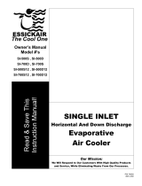
2. This cooler is designed so the duct will fit between two wall studs. On the outside
of the wall where the cooler is to be mounted, locate the two studs between
which you wish to mount your cooler. Mark an opening approximately 14” wide
by 21 ¾” tall between the two wall studs. Ensure the area inside the garage is
suitable for the cooler. Also, mark your opening high enough that the bottom of
the cooler is at least 8” off the ground for water inlet and drain. (Figure 1)
3. Cut the opening. If the inside of the mounting wall is finished, the mounting hole
will need to be cut through the inside of the wall also.
4. Remove the front of the duct. (Figure 2)
a. Remove the grill (one phillips head screws in each corner).
b. Remove the switch bracket (two phillips head screws).
c. Remove the flange nut from each of the four weld studs (back side of
front duct section).
d. Extend the duct fully, lift up on the four duct brackets and remove the
front duct section.
5. Place the cooler flush against the wall with the duct back section in the
hole. CAUTION: Until the duct front section is reinstalled, the cooler
is not secured to the wall.
6. Reinstall the duct front section. To avoid cooler damage, ensure the
cooler is held securely in the wall opening. Lift the duct brackets over
the weld studs and replace the flange nuts.
7. Collapse the duct until the duct front section is flush to the wall and tighten
the flange nuts. NOTE: the duct only collapses to 5 ½ “ deep. If your
wall is narrower than this, you will need to trim around the inside
opening to fill the gap. (Figure 3)
8. Replace the switch bracket and grill.
9. To seal the cooler to the wall, run a bead of silicon calk around the edges of the cabinet. (Figure 4)
3
Figure2
16"
Figure
Figure 3
Figure4

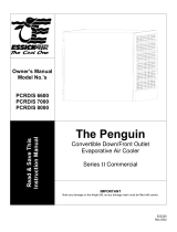
INSTALL OVERFLOW AND DRAIN
NOTE: There are two overflow assemblies supplied with this unit. Install one in
each of the openings in the bottom pan. One overflow assembly is to route water
tubing to the float.
Reservoir
1. Slide the Rubber Washer over the Drain Bushing and push through the hole in the
bottom of the cooler from the topside.
2. Secure the Drain Bushing from beneath the pan with the Lock Nut. Make sure the
Rubber Washer does not twist while tightening, which could cause it to leak. DO NOT
OVERTIGHTEN.
3. Thread the Overflow Tube into the Drain Bushing and HAND TIGHTEN.
4. If leakage occurs after Reservoir is full, retighten the Overflow Pipe until leaking stops.
A small amount of silicone caulk may be used if necessary.
FLOAT VALVE INSTALLATION
1. Place the threaded portion of the Float Valve through the hole provided in the
Float Bracket (inside unit) as shown.
2. Slip the Fiber Washer over the threaded portion of the float and secure with the
Ring Nut. Be sure the Float does not turn while you are tightening the nut.
WATER LINE CONNECTION
1. Find the closest outside water faucet, and install a Water Connection Kit (not
included with cooler) as shown. If an exterior faucet is not available, locate the
closest cold water pipe and install a saddle valve assembly.
2. Route tubing into cooler through one of the overflow assemblies as shown. Place
Compression Nut and Ferrule over end of tubing. Insert the tubing into float valve
and tighten Compression Nut to secure.
NOTE: Over tightening a compression fitting will cause that fitting to leak. It is best
to secure the connections, turn on the water, and then snug the fitting until leaking stops.
ADJUSTING WATER LEVEL AND FLOAT VALVE
1. To adjust water level, bend the float valve rod.
2. Check all water connections for leaks.
3. Make sure the Float Valve cuts off completely when the desired water level has
been reached (½” to ¾” below top of Overflow Tube). If the float does not stop
the water completely, the water level will rise and run out the Overflow Tube.
4. Double-check the Overflow Tube for leaks.
START UP
1. Plug in the electrical cord to a standard grounded receptacle.
2. Turn the cooler to the Pump Only position. The pump should run and not the fan.
Check to see that the pads are wetting evenly. The Pads may take up to 20 minutes to wet fully.
Ferrule
Faucet
3. Turn the cooler to the High Cool position. The pump should remain running and the fan should run on high speed.
4. Turn the cooler to the Low Cool position. The pump should remain running and the fan should run on low speed.
5. Turn the cooler to the High Vent position. The fan should deliver the same airflow as in High Cool.
6. Turn the cooler to the Low Vent position. The fan should deliver the same airflow as in Low Cool.
Note: on cool nights (or days) or when the humidity level is high, the fan positions may be used for ventilation purposes.
MAINTENANCE
1. Once a month during cooling season, inspect your cooler for leaks, blocked water lines and excessive residue build-up
on the pads.
2. At the end of the season, drain the reservoir. Remove the drainpipe and let water and dirt pass through the drain fitting.
3. Lime build-up can occur in the water reservoir and on louvers. Clean this off at least once per season. If any rust or
bare metal spots occur on the cabinet or louver, the metal should be sanded, primed and painted with good quality
paint.
4. If freezing weather occurs in your area, it is best to shut off the water supply at the source and drain the supply line to
the cooler.
4

DO NOT GET WATER ON MOTOR OR PUMP MOTOR
NOTE: Depending on the mineral content of the water or the amount of air borne dust in your area, pad life may vary.
When it comes time to replace your pads, It is best to replace filter pads at the end of the season.
Old filter pads soak up lime and salts, which can rust the louvers and the cabinet during the winter months.
PAD MAINTENANCE
It is recommended that the pads be changed after the third season or after 9 to 12 months of total operation. However,
the pads need to be cleaned regularly.
1. Remove louvers from cooler.
2. Rinse the pads with a gentle stream of water.
3. Clean any mineral deposits from the trays.
4. If excessive minerals deposits are collecting on the pads, remove pads from louvers and soak in a solution of 4 parts
water to one part vinegar. Rinse pads thoroughly before replacing in the louvers.
TO REPLACE PADS
1. Remove louvers from cooler.
2. Remove tray from louver (2 phillips head screws).
3. Remove old pads (slide up and out of louver) and discard.
4. Slide new pads into place.
5. Replace tray.
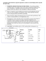
WIRING DIAGRAM
TROUBLE SHOOTING
Problem Cause Remedy
• Extension cord (if one used) too long • Choose a shorter or heavier gauge cord
Motor cycles on and off
• Circuit breaker not large enough • Consult a licensed electrician
• No electrical power • Check all electrical connections and cords
Fails to start
• Circuit breaker tripped or fuse blown • Reset circuit breaker or replace fuse
Water draining from
overflow
• Float improperly adjusted • Adjust float
• Blower wheel out of balance or out of
alignment
• Replace the blower wheel
Blower vibrates excessively
or rattles
• Debris in blower housing • Clear debris
• Blocked water lines
• Check incoming water line, float and water
distributor for blockages and clear.
• Windows opened too little or too much • Adjust window openings
• Pump clogged or failed • Clean pump or replace
Not cooling
• Pads plugged with dirt and water
deposits
• Replace pads
5

Item Description Qty Part No. Item Description Qty Part No.
1 Grille Frame 1 70658 17 Water Distributor 1 71212
2 Sub-Vent Assembly 1 70741 18 Top 1 71204
3 Duct Front 1 71219 19 Blower Housing 1 70367
4 Duct Back 1 71207 20 Blower Wheel 1 70424
5 Knob 1 70664 21 Motor 1 70423
6 Switch Bracket 1 70798 22 Inlet Ring 1 70425
7 Switch 1 524299 23 Motor Mount Bushing 4 589040
8 Electrical box 1 524342 24 Motor Mount 2 70431
9 Pump Bracket 1 504281 25 Louver 1 71205
10 Pump 1 70569 26 Water Tray 2 71211
11 Duct Bracket 4 71206 27 Water Distributor Pad 2 71199
12 Water Overflow Kit 2 506667 28 Evaporative Pad 2 71198
13 Float Bracket 1 70373 29 Baffle 1 71223
14 Float Valve 1 502389 30 Cord 1 70414
15 Cabinet 1 71209 Louver Assembly * 2 71210
16 Water Tube 1 70276 Blower Assembly * 1 70366
* Louver Assembly includes items 25, 26, 27 and 28.
* Blower Assembly includes items 19, 20, 21, 22, 23 and 24.
6

LIMITED WARRANTY
This warranty is extended to the original purchaser only. It does not cover damages incurred during shipping or
through accident, neglect, or abuse by the owner. Essick Air Products does not authorize any person or representative to
assume any other or different liability in connection with this cooler.
TERMS AND CONDITIONS OF WARRANTY
The CABINET is guaranteed against leakage due to rusting out for EIGHT YEARS. The EVAPORATIVE MEDIA is
guaranteed for TWO YEARS. The PUMP is warranted for TWO YEARS. All other original parts provided by Essick Air
Products are warranted against defects in material or factory workmanship for One Year.
EXCLUSIONS FROM THE WARANTY
Essick Air Products is not responsible for incidental or consequential damage resulting from any malfunction.
Essick Air Products is not responsible for any damage occurring from the use of water softeners, chemicals, descale
material, or if a higher horsepower motor than what Essick Air Products recommends is used in the unit.
Essick Air Products is not responsible for the cost of service calls to diagnose cause of trouble, or labor charge to repair
and/or replace parts.
HOW TO OBTAIN SERVICE UNDER THIS WARRANTY
Contact the Dealer where you purchased the evaporative cooler. If for any reason you are not satisfied with the response
for the Dealer, contact Customer Service Department: Essick Air Products Inc. 5800 Murray Street, Little Rock, Arkansas
72209. 1-800-643-8341.
7

8
THIS PAGE BLANK
/