Electrolux EN19WI30LS Installation guide
- Category
- Water heaters & boilers
- Type
- Installation guide
This manual is also suitable for

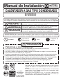
EN CONDENSING TANKLESS GAS WATER HEATER Installation Manual
SBB800T-1
Rev. 09/13
*SBB800T*
SP CALENTADOR A GAS TIPO CONDENSADO Manual de Instalación
5995615357 September 2013
Page is loading ...

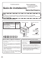
Installation Manual
CONDENSING TANKLESS GAS WATER HEATER
EN19WI30LS
EP19WI30LS
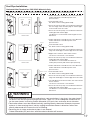
Potential dangers from accidents during installation and use are divided into the following three
categories. Closely observe these warnings, they are critical to your safety.
Prohibited
Disconnect
Power
Ground
Be sure to do
WARNING:
If the information in this manual is not followed exactly, a re or explosion may result
causing property damage, personal injury or death.
DANGER indicates an imminently hazardous situation which,
if not avoided, will result in death or serious injury.
WARNING indicates a potentially hazardous situation which,
if not avoided, could result in death or serious injury.
CAUTION indicates a potentially hazardous situation which,
if not avoided, may result in minor or moderate injury.
DANGER
WARNING
CAUTION
Requests to Installers
r*OPSEFSUPVTFUIFXBUFSIFBUFSTBGFMZSFBEUIJTJOTUBMMBUJPONBOVBMDBSFGVMMZBOEGPMMPXUIF
installation instructions.
r'BJMVSFTBOEEBNBHFDBVTFECZFSSPOFPVTXPSLPSXPSLOPUBTJOTUSVDUFEJOUIJTNBOVBMBSFOPU
covered by the warranty.
r
$IFDLUIBUUIFJOTUBMMBUJPOXBTEPOFQSPQFSMZJOBDDPSEBODFXJUIUIJT*OTUBMMBUJPO.BOVBMVQPODPNQMFUJPO
r
"GUFSDPNQMFUJOHJOTUBMMBUJPOQMFBTFFJUIFSQMBDFUIJT*OTUBMMBUJPO.BOVBMJOBQMBTUJDQPVDIBOE
attach it to the side of the water heater (or the inside of the pipe cover or recess box if applicable),
or hand it to the customer to retain for future reference. Also, be sure to ll in all of the required
items on the registration/warranty card and to hand the registration/warranty card to the customer
BMPOHXJUIUIF6TFBOE$BSF.BOVBM
CAUTION
'0364&*/3&4*%&/5*"-"11-*$"5*0/4*/5)&6/*5&%45"5&40/-:
/05*/5&/%&%'0364&*/$"/"%"03.&9*$0
Installation must conform with local codes, or in the absence of local codes,
UIF/BUJPOBM'VFM(BT$PEF"/4*;/'1"MBUFTUFEJUJPO
&MFDUSPMVY)PNF1SPEVDUT*ODSFTFSWFTUIFSJHIUUPEJTDPOUJOVFPS
change at any time, the designs and/or specications of its products
without notice.
Low NOx
Approved by
4$"2.%
OH+PSQQN
(Natural Gas Only)

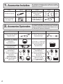
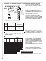
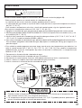
1.
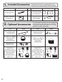
Included Accessories
The following accessories are included with the unit.
$IFDLGPSBOZNJTTJOHJUFNTCFGPSFTUBSUJOHJOTUBMMBUJPO
Q’ty
ShapePart
Anchoring Screw
1
each
Part Shape
Q’ty
1
Remote Controller
(See page 31)
Remote Controller
$PSEGUN
3$$03%
1
2.
Optional Accessories
The accessories listed below are not included with
the units, but may be necessary for installation.
$POUBDU&MFDUSPMVY)PNF1SPEVDUT*ODBU
GPSGVSUIFSJOGPSNBUJPO
ShapePartPart Shape
2VJDL$POOFDU$PSE
58)2$$03%
6TFBOE$BSF.BOVBM
8BSSBOUZ*OTUBMMBUJPO.BOVBM
(this document)
NN17$5FSNJOBM
58))03$0/$
NNNN
)PSJ[POUBM)PPE
Termination
58))03)00%
NNNN
7FSUJDBM3BJO$BQ
Termination
58)7&35$"1
)PSJ[POUBM*OTUBMMBUJPO,JU
58))03,*5
*TPMBUJPO7BMWFT
1SFTTVSF3FMJFG7BMWF
)PSJ[POUBM)PPE
Termination,
47$POWFSTJPO,JU
(47$,)
7FSUJDBM*OTUBMMBUJPO,JU
58)7&35,*5
*TPMBUJPO7BMWFT
1SFTTVSF3FMJFG7BMWF
7FSUJDBM3BJO$BQ
Termination,
47$POWFSTJPO,JU
(47$,)
/FVUSBMJ[FS,JU
58)/&653"-

3
G
Quick Connect
Cor
d
Remote Controller Cord
Gas Supply Piping
Cold Water Supply
Hot Water
Remote Controller
Terminal Block
Cord
Connector
Cord
Connector
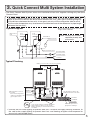
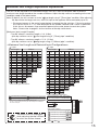
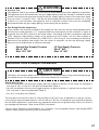
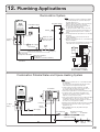
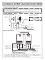
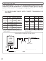
3.
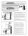
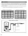
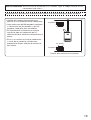
Quick Connect Multi System Installation
r5IF2VJDL$POOFDU.VMUJ4ZTUFNBMMPXTUIFJOTUBMMBUJPOPGUXPVOJUTUPHFUIFSVUJMJ[JOHPOMZUIF2VJDL
Connect Cord.
Typical Plumbing
* When connecting two units, use only a
single remote controller.
Note: Connect the remote
controller to only one
of the units.
System Diagram
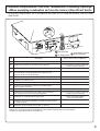
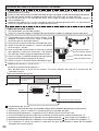
r*OTVMBUF UIF IPU XBUFS QJQJOH UP QSFWFOU IFBU MPTT *OTVMBUF BOE BQQMZ IFBUJOH NBUFSJBMT UP
the cold water supply piping to prevent heat loss and freezing of pipes when exposed to
excessively cold temperatures.
Union
Make this distance as short
as possible.
* The hot water temperatur
e
will become unstable as the
pipe length incr
eases.
Distance at center: 20.3 - 36.3 in. (515 - 922mm)
Quick Connect Cord
Union
Gas Valve
Union
Shutoff Valve
Shutoff Valve
Hot Water
Shutoff Valve
Cold Water
Distance on sides
2 - 18 in. (50 - 457mm)
Leave enough clearance around the plumbing to
apply insulation. It will be necessary to add
bends to the piping to ensure that this clearance
is available.
Size the piping to allow for the
maximum ow rates of the units.
The backow preventer is
put up before it diverges.
Pressure
Relief Valve
5IF2VJDL$POOFDU$PSEJTGUNMPOH*OTUBMMUIFVOJUTNNBQBSUGSPNFBDI
other to ensure the cord will be able to reach between the units. (See Typical Plumbing diagram).
(If the distance between the two units is too great, not only will the cord not be able to reach,
but the water temperature may also become unstable because of the difference in pipe length
between the two units).

199,900 192,700
199,900 BTU
16,000 BTU
228
4.0
1.3 2.8"
10.5"
ANSI Z21.10.3-2011/CSA 4.3-2011
15
150
4
EN19WI30LS1
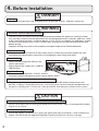
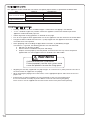
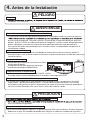
4.
Before Installation
Checkup
r$IFDLUIFàYJOHCSBDLFUTBOEWFOUQJQFZFBSMZGPSEBNBHFPSXFBS3FQMBDFJGOFDFTTBSZ
DANGER
Do Not Use Equipment for Purposes Other Than Those Specified
r%POPUVTFGPSPUIFSUIBOJODSFBTJOHUIFUFNQFSBUVSFPGUIFXBUFSTVQQMZBTVOFYQFDUFEBDDJEFOUT
may occur as a result.
Check Water Supply Quality
r*GUIFXBUFSTVQQMZJTJOFYDFTTPGHSBJOTQFSHBMMPONH-PGIBSEOFTTBDJEJDPSPUIFSXJTF
impure, treat the water with approved methods in order to ensure full warranty coverage.
WARNING
CAUTION
Check the Gas
r$IFDLUIBUUIFSBUJOHQMBUFJOEJDBUFTUIF
correct type of gas.
r$IFDLUIBUUIFHBTTVQQMZMJOFJTTJ[FEGPS
199,900 Btuh.
Check the Power
r5IFQPXFSTVQQMZSFRVJSFEJT7"$BU)[
6TJOHUIFJODPSSFDUWPMUBHFNBZSFTVMUJOàSFPSFMFDUSJDTIPDL
Use Extreme Caution if Using With a Solar Pre-Heater
r6TJOHUIJTVOJUXJUIBTPMBSQSFIFBUFSDBOMFBEUPVOQSFEJDUBCMFPVUQVUUFNQFSBUVSFTBOE
possibly scalding. If absolutely necessary, use mixing valves to ensure output temperatures do
OPUHFUUPTDBMEJOHMFWFMT%POPUVTFBTPMBSQSFIFBUFSXJUIUIFRVJDLDPOOFDUNVMUJTZTUFN
Precautions on Vent Pipe Replacement
r5IFWFOUTZTUFNXJMMBMNPTUDFSUBJOMZOFFEUPCFSFQMBDFEXIFOUIJTBQQMJBODFJTCFJOHJOTUBMMFE
0OMZVTFWFOUNBUFSJBMTUIBUBSFTQFDJàFEJOUIJT*OTUBMMBUJPO.BOVBMGPSVTFPOUIJTBQQMJBODF3FGFS
UPUIF7FOU1JQF*OTUBMMBUJPOTFDUJPOGPSEFUBJMT*G17$$17$PS$BUFHPSZ*7MJTUFEQJQFJTBMSFBEZ
JOTUBMMFEDIFDLGPSQVODUVSFTDSBDLTPSCMPDLBHFTBOEDPOTVMUXJUIUIFWFOUQJQFNBOVGBDUVSFS
before reusing.
*NQSPQFSWFOUJOHNBZSFTVMUJOàSFTQSPQFSUZEBNBHFPSFYQPTVSFUP$BSCPO.POPYJEF
Snow Precaution
r*GUIJTQSPEVDUXJMMCFJOTUBMMFEJOBOBSFBXIFSFTOPXJTLOPXOUPBDDVNVMBUFQSPUFDUUIFWFOU
UFSNJOBUJPOGSPNCMPDLBHFCZTOPXESJGUTPSEBNBHFGSPNTOPXGBMMJOHPGGPGSPPGT

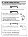
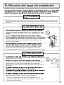
5.
Choosing Installation Site
-PDBUFUIFBQQMJBODFJOBOBSFBXIFSFMFBLBHFGSPNUIFVOJUPSDPOOFDUJPOTXJMMOPUSFTVMUJOEBNBHF
to the area adjacent to the appliance or to the lower oors of the structure. When such locations
cannot be avoided, it is recommended that a suitable drain pan, adequately drained, be installed
under the appliance. The pan must not restrict combustion air ow.
rLocate the vent terminal so that there are no obstacles around the termination and so that exhaust
can't accumulate. Do not enclose the termination with corrugated metal or other materials.
r"WPJEQMBDFTXIFSFàSFTBSFDPNNPOTVDIBTUIPTFXIFSFHBTPMJOF
benzene and adhesives are handled, or places in which corrosive gases
(ammonia, chlorine, sulfur, ethylene compounds, acids) are present.
6TJOHUIFJODPSSFDUWPMUBHFNBZSFTVMUJOàSFPSDSBDLJOH
r"WPJEJOTUBMMBUJPOJOQMBDFTXIFSFEVTUPSEFCSJTXJMMBDDVNVMBUF
%VTUNBZCMPDLUIFBJSTVQQMZPQFOJOHDBVTJOHUIFQFSGPSNBODFPGUIF
device fan to drop and incomplete combustion to occur as a result.
r"WPJEJOTUBMMBUJPOJOQMBDFTXIFSFTQFDJBMDIFNJDBMBHFOUT
(e.g., hair spray or spray detergent) are used.
Ignition failures and malfunction may occur as a result.
r$BSCPO.POPYJEF1PJTPOJOH)B[BSE%POPUJOTUBMMUIJTXBUFSIFBUFSJOB
mobile home, recreational vehicle or on a boat.
r5IFXBUFSIFBUFSJTEFTJHOFEGPSJOEPPSJOTUBMMBUJPOPOMZ/FWFSJOTUBMMJU
outdoors or in a bathroom, it may be damaged or a re may be caused.
r$POTVMUXJUIUIFDVTUPNFSDPODFSOJOHUIFMPDBUJPOPGJOTUBMMBUJPO
rInstall the water heater in an area that allows for the proper clearances
to combustible and noncombustible construction. Consult the rating
plate on the appliance for proper clearances.
r%POPUJOTUBMMUIFXBUFSIFBUFSJOBQMBDFXIFSFJUNBZCFUISFBUFOFECZ
falling objects, such as under shelves.
r5IFXBUFSIFBUFSNVTUCFJOTUBMMFEJOBQMBDFXIFSFTVQQMZBOEFYIBVTU
pipes can be installed as directed.
r%POPUJOTUBMMUIFXBUFSIFBUFSXIFSFUIFFYIBVTUXJMMCMPXPOPVUFS
walls or material not resistant to heat. Also consider the surrounding
trees and animals.
The heat and moisture from the water heater may cause discoloration
of walls and resinous materials, or corrosion of aluminum materials.
DANGER
WARNING
CAUTION
Prohibited
Prohibited

6
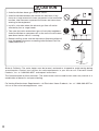
r"WPJEJOTUBMMBUJPOBCPWFHBTSBOHFTPSTUPWFT
r"WPJEJOTUBMMBUJPOCFUXFFOUIFLJUDIFOGBOBOETUPWF*GPJMZ
fumes or a large amount of steam are present in the installation
MPDBUJPOUBLFNFBTVSFTUPQSFWFOUUIFGVNFTBOETUFBNGSPN
entering in the equipment.
r*OTUBMMJOBMPDBUJPOXIFSFUIFFYIBVTUHBTáPXXJMMOPUCF
affected by fans or range hoods.
r5BLFDBSFUIBUOPJTFBOEFYIBVTUHBTXJMMOPUBGGFDUOFJHICPST
"WPJEJOTUBMMBUJPOPODPNNPOXBMMTBTUIFVOJUXJMMNBLFTPNF
operational noises while it is running.
r#FGPSFJOTUBMMJOHNBLFTVSFUIBUUIFFYIBVTUáVFUFSNJOBUJPOXJMM
IBWFUIFQSPQFSDMFBSBODFTBDDPSEJOHUPUIF/BUJPOBM'VFM(BT
$PEF"/4*;
Be sure to do
Prohibited
Prohibited
CAUTION
State of California: The water heater must be braced, anchored or strapped to avoid moving during
BOFBSUIRVBLF$POUBDUMPDBMVUJMJUJFTGPSDPEFSFRVJSFNFOUTJOZPVSBSFBPSDBMM&MFDUSPMVY)PNF
1SPEVDUT*ODBUBOESFRVFTUJOTUSVDUJPOT
5IF$PNNPOXFBMUIPG.BTTBDIVTFUUT5IFXBUFSIFBUFSDBOCFVTFEGPSIPUXBUFSPOMZBOEOPUJOB
combination of domestic and space heating.
'PS7FOUJOH.BOVGBDUVSFST3FRVJSFNFOUTDBMM&MFDUSPMVY)PNF1SPEVDUT*ODBUPS
visit us at www. electroluxappliances. com.

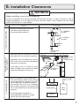
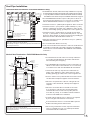
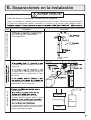
6.
Installation Clearances
#FGPSFJOTUBMMJOHDIFDLGPSUIFGPMMPXJOH
Install in accordance with relevant building and mechanical codes, as well as any local, state or
OBUJPOBMSFHVMBUJPOTPSJOUIF BCTFODF PG MPDBMBOETUBUFDPEFTUP UIF /BUJPOBM'VFM(BT$PEF
"/4*;/'1"mMBUFTUFEJUJPO
WARNING
Item
Distance from combustibles
r.BJOUBJOUIFGPMMPXJOHDMFBSBODFT
from both combustible and
OPODPNCVTUJCMFNBUFSJBMT
$IFDL Illustration
r*GQPTTJCMFMFBWFNNPSNPSFPO
either side of the unit to facilitate inspection.
r*GQPTTJCMFMFBWFNNPSNPSFJO
front of the unit to facilitate maintenance
and service if necessary.
r*G QPTTJCMF MFBWF NN PS NPSF
above and below the vent pipe to facilitate
inspection and repair if necessary.
Securing of space for
repair/inspection
NN
or more
Distance from
the side
NN
or more
NN
or more
NN
or more
NNPSNPSF
NNPSNPSF
NN
or more
NN
or more
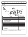
<When using indoor air for combustion>
r*GUIFVOJUXJMMCFJOTUBMMFEJOUIFWJDJOJUZPG
BQFSNBOFOULJUDIFOSBOHFPSTUPWFUIBU
has the possibility of generating steam
that contains fats or oils, use a *dividing
plate or other measure to ensure that the
unit is not exposed to air containing such
impurities.
* The dividing plate should be of
noncombustible material of a width
greater than the water heater.
Exhaust hood
Range
Dividing plate
Water
heater
$PPLJOH&RVJQNFOU

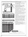
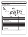
DescriptionRef
A=
Clearance above grade, veranda, porch, deck, or balcony
B=
Clearance to window or door that may be opened
C=
Clearance to permanently closed window
D=
Vertical clearance to ventilated soffit located above the
terminal within a horizontal distance of 2 feet (61 cm)
from the center line of the terminal
E=
Clearance to unventilated soffit
F=
Clearance to outside corner
G=
Clearance to inside corner
H=
Clearance to each side of center line extended above
meter/regulator assembly
I=
Clearance to service regulator vent outlet
J=
Clearance to nonmechanical air supply inlet to building or
the combustion air inlet to any other appliance
K=
Clearance to a mechanical air supply inlet
L=
Clearance above paved sidewalk or paved driveway located
on public property
Clearance under veranda, porch, deck, or balcony
M=
1
In accordance with the current ANSI Z223.1 / NFPA 54 National Fuel Gas Code
* Clearance in accordance with local installation codes and the requirements of the gas supplier
.
b Clearance to opposite wall is 24 inches (60 cm).
12 in (30 cm)
*
*
*
*
*
*
*
*
3 ft (91 cm) above if within
10 ft (3 m) horizontally
*
12 in (30 cm)
12 in (30 cm)
US Direct Vent Installations
1
Vent Terminal
D
E
B
B
F
B
A
G
H
I
C
B
M
K
J
B
B
L
Air Supply Inlet
Area Where Termina
l
is Not Permitted
A
Clearance Requirements from Vent Terminations to Building Openings
<When supplying combustion air from the outdoors (Direct Vent)>
"MMDMFBSBODFSFRVJSFNFOUTBSFJOBDDPSEBODFXJUI"/4*;BOEUIF/BUJPOBM'VFM(BT$PEF
"/4*;

9
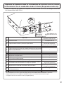
DescriptionRef
A=
Clearance above grade, veranda, porch, deck, or balcony
B=
Clearance to window or door that may be opened
C=
Clearance to permanently closed window
D=
Vertical clearance to ventilated soffit located above the
terminal within a horizontal distance of 2 feet (61 cm)
from the center line of the terminal
E=
Clearance to unventilated soffit
F=
Clearance to outside corner
G=
Clearance to inside corner
H=
Clearance to each side of center line extended above
meter/regulator assembly
I=
Clearance to service regulator vent outlet
J=
Clearance to nonmechanical air supply inlet to building or
the combustion air inlet to any other appliance
K=
Clearance to a mechanical air supply inlet
L=
Clearance above paved sidewalk or paved driveway located
on public property
Clearance under veranda, porch, deck, or balcony
M=
1
In accordance with the current ANSI Z223.1 / NFPA 54 National Fuel Gas Code
* Clearance in accordance with local installation codes and the requirements of the gas supplier
.
b Clearance to opposite wall is 24 inches (60 cm).
*
*
*
*
*
*
*
*
3 ft (91 cm) above if within
10 ft (3 m) horizontally
*
12 in (30 cm)
US Non-Direct Vent Installations
2
Vent Terminal
D
E
B
B
F
B
A
G
H
I
C
B
M
K
J
B
B
L
Air Supply Inlet
Area Where Termina
l
is Not Permitted
A
4 ft (1.2 m) below or to side of opening;
1 ft (30 cm) above opening
4 ft (1.2 m) below or to side of opening;
1 ft (30 cm) above opening
Clearance Requirements from Vent Terminations to Building Openings
<When supplying combustion air from the indoors (Non-Direct Vent)>
"MMDMFBSBODFSFRVJSFNFOUTBSFJOBDDPSEBODFXJUI"/4*;BOEUIF/BUJPOBM'VFM(BT$PEF
"/4*;

10
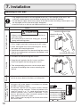
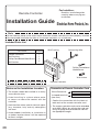
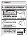
7.
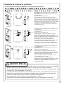
Installation
Securing to the wall
Illustration
$IFDL
%SJMMIPMFTGPSUIFSFNBJOJOHGPVSTDSFXT
)BOHUIFVOJUBHBJOCZUIFàSTUTDSFXBOEUIFO
insert and tighten the remaining four screws.
5BLFXBUFSQSPPàOHNFBTVSFTTPUIBUXBUFSEPFT
not enter the building from screws mounting the
device.
r.BLFTVSFUIFVOJUJTJOTUBMMFETFDVSFMZTPUIBUJUXJMM
OPUGBMMPSNPWFEVFUPWJCSBUJPOTPSFBSUIRVBLFT
%SJMMBTJOHMFTDSFXIPMFNBLJOHTVSFUPIJUBTUVE
*OTFSUBOEUJHIUFOUIFTDSFXBOEIBOHUIFVOJUCZ
UIFVQQFSXBMMNPVOUJOHCSBDLFU
3. Determine the positions for the remaining four screws
UXPGPSUIFUPQCSBDLFUBOEUXPGPSUIFCPUUPNBOE
remove the unit.
r5IFXFJHIUPGUIFEFWJDFXJMMCFBQQMJFEUPUIFXBMM*GUIFTUSFOHUIPGUIFXBMMJTOPU
sufcient, reinforcement must be done to prevent the transfer of vibration.
r%POPUESPQPSBQQMZVOOFDFTTBSZGPSDFUPUIFEFWJDFXIFOJOTUBMMJOH*OUFSOBMQBSUTNBZ
be damaged and may become highly dangerous.
r*OTUBMMUIFVOJUPOBWFSUJDBMXBMMBOEFOTVSFUIBUJUJTMFWFM
-PDBUJOH4DSFX)PMFT
.PVOUJOH
Structure
r8IFOJOTUBMMJOHXJUICBSFIBOETUBLFDBVUJPOUP
not inict injury.
r#FDBSFGVMOPUUPIJUFMFDUSJDBMXJSJOHHBTPSXBUFS
piping while drilling holes.
Item
CAUTION
Be sure to do
.PVOUJOH#SBDLFU
(upper)
-PDBUJPOPG4DSFX)PMF
-PDBUJOH4DSFX)PMFT
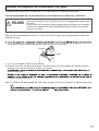
Installations at Elevations
"CPWFGU
r"EKVTUUIF EJQTXJUDIFTBT JMMVTUSBUFEJOUIF UBCMFUP
the right if this water heater is installed at an altitude
PGGUNPSIJHIFS
r%JTDPOOFDU QPXFS UP UIF XBUFS IFBUFS CFGPSF
DIBOHJOH UIF EJQ TXJUDIFT 'BJMVSF UP QFSGPSN UIJT
TUFQ XJMM SFTVMU JO B DPEF EJTQMBZFE PO UIF
remote controller and a cease in operation. If this
occurs, disconnect, then reconnect power to the
water heater to reset the system.
Note : Please refer to page 31 for the location of the
EJQTXJUDICBOL
Anchoring Screw
* Do not change any other dipswitches.
* High elevation adjustment.
65
2,001 - 4,000 ft (611 - 1,220m)
0 - 2,000 ft (0 - 610m)
ON= OFF=
4,001 - 6,000 ft (1,221 - 1,830m)
6,001 - 8,000 ft (1,831 - 2,440m)

11
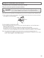
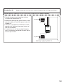
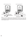
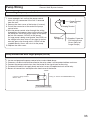
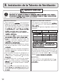
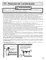
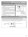
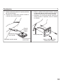
Filling the condensate trap with water
The condensate trap can be lled before connecting the vent pipe.
Filling the condensate trap before vent pipe installation.
DANGER
1SJPSUPJOJUJBMTUBSUVQNBLFTVSFUIBUZPVàMMUIFDPOEFOTBUFUSBQXJUIXBUFS
This is to prevent dangerous exhaust gases from entering the building.
'BJMVSFUPàMMUIFDPOEFOTBUFUSBQDPVMESFTVMUJOTFWFSFQFSTPOBMJOKVSZPSEFBUI
Please follow one of the procedures described below to ensure that the condensate trap is lled with water.
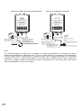
'JMMUIFDPOEFOTBUFUSBQCZQPVSJOHBQQSPYP[NMPGXBUFSJOUPUIFFYIBVTUBDDFTTPSZPOUIFUPQ
of the appliance as illustrated below.
Or, if the vent pipe has already been installed:
"GUFSJOTUBMMJOHUIFESBJOQJQFNBLFTVSFUIBUUIFBSFBBSPVOEUIFBQQMJBODFJTXFMMWFOUJMBUFEPQFOB
window or a door if necessary.
Then, operate the unit and verify that condensate is coming out of the drain pipe.
(During normal use of the water heater, condensate will begin to discharge from the drain pipe within
NJOVUFTPGVTF)PXFWFSEFQFOEJOHPOUIFTFBTPOBOEPSJOTUBMMBUJPOTJUFDPOEJUJPOTJUNBZUBLFMPOHFS
/PUF5IFDPOEFOTBUFEJTDIBSHFEGSPNUIFXBUFSIFBUFSIBTBQ)MFWFMPGBQQSPYJNBUFMZ
If required by local code, the condensate must be neutralized prior to disposal into the sewer
system.
3FGFSUPQBHFTGPSBEEJUJPOBMEFUBJMT
30 oz.
850ml
*OUBLF
Exhaust

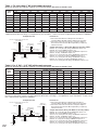
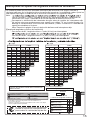
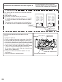
Maximum Vent Lengths
rThis appliance has been designed to be vented
XJUI FJUIFS NN PS NN 17$ PS
$17$QJQF
Do not exceed the following maximum vent lengths:
* Not including the termination
Refer to page 16 for max. vent lengths
XIFOVTJOHUFSNJOBUJPO58))03$0/$
r.BJOUBJOUIFTBNFWFOUQJQFEJBNFUFSGSPNUIF
heater ue to the vent termination. The exhaust
BOE JOUBLF QJQFT NVTU CF UIF TBNF WFOU QJQF
diameter.
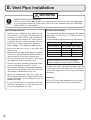
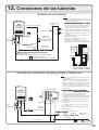
8.
Vent Pipe Installation
WARNING
Be sure to do
$"3#0/.0/09*%&10*40/*/(
'PMMPXBMMWFOUTZTUFNSFRVJSFNFOUTJOBDDPSEBODFXJUISFMFWBOUMPDBMPSTUBUFSFHVMBUJPO
PSJOUIFBCTFODFPGMPDBMPSTUBUFDPEFJOUIF64UPUIF/BUJPOBM'VFM(BT$PEF"/4*
;/'1"mMBUFTUFEJUJPO
No. of Elbows
.BY4USBJHIU7FOU-FOHUI
/" hN
hN hN
hN hN
hN hN
Pipe diameter NN NN
r6OEFS OPSNBM DPOEJUJPOT UIJT BQQMJBODF XJMM
not produce an exhaust flue temperature
JO FYDFTT PG ' $ BOE TDIFEVMF
17$QJQFNBZCFVTFEBTUIFWFOUNBUFSJBM
*GSFRVJSFECZMPDBMDPEFTDIFEVMFPS
$17$NBZBMTPCFVTFEPOUIJTBQQMJBODF
3FGFSUPQBHFGPSBEEJUJPOBMSFRVJSFNFOUT
r.BLF TVSF UIFWFOU TZTUFN JT HBT UJHIU BOE
XJMMOPUMFBL
r4VQQPSUUIFWFOUQJQFXJUIIBOHFSTBUSFHVMBS
intervals as specied by these instructions or
the instructions of the vent manufacturer.
r%P OPUDPNNPO WFOUPS DPOOFDUNPSFUIBO
one appliance to this venting system.
r
The total vent length including horizontal & vertical
vent runs should be no less than 3' (0.9m).
r%POPUTUPSFIB[BSEPVTPSáBNNBCMFTVCTUBODFT
OFBSUIFWFOUUFSNJOBUJPOBOEDIFDLUIBUUIF
UFSNJOBUJPOJTOPUCMPDLFEJOBOZXBZ
r4UFBN PSDPOEFOTFEXBUFS NBZ DPNF PVU
from the vent termination. Select the location
for the termination so as to prevent injury or
property damage.
r*GTOPXJTFYQFDUFEUPBDDVNVMBUFUBLFDBSF
the end of the pipe is not covered with snow
or hit by falling lumps of snow.
General Requirements
Clearances
17$PS$17$IBTCFFOBQQSPWFEGPSVTFPOUIJT
appliance with zero clearance to combustibles.

13
5IFVOJUDBOCFBEKVTUFEUPBDDPNNPEBUFMPOHFSWFOUSVOTSFGFSUPUIFCFMPXUBCMFUPàOEUIF
maximum vent length based on the number of elbows. Adjust the dip switches according to the vent
condition noted in the tables below.
Note:
#ZEFGBVMUUIFVOJUIBTCFFOTFUUPUIFTIPSUMFOHUIVTJOHNNQJQFDPOEJUJPO8IFOBEKVTUJOH
UIFEJQTXJUDIFTGPSMPOHFSWFOUSVOTUIF#56)JOQVUPGUIFBQQMJBODFXJMMCFSFEVDFECZVQUP
Maximum Vent Length Adjustment Dipswitches
5XP elbows, maximum length = 3 ft. (0.9m)
XJUIEJQTXJUDIFTTFUBUTIPSUMFOHUIVTJOHNNQJQFDPOEJUJPO
5XPFMCPXTNBYJNVNMFOHUIGUN
XJUIEJQTXJUDIFTTFUBUMPOHMFOHUIVTJOHNNQJQFDPOEJUJPO
<.BYJNVN7FOU-FOHUI&YBNQMF>
r%JTDPOOFDUQPXFSUPUIFXBUFSIFBUFSCFGPSFDIBOHJOHUIFEJQTXJUDIFT'BJMVSFUPQFSGPSN
UIJTTUFQXJMMSFTVMUJOBDPEFEJTQMBZFEPOUIFSFNPUFDPOUSPMMFSBOEBDFBTFJOPQFSBUJPO
.
If this occurs, disconnect, then reconnect power to the water heater to reset the system.
/PUF1MFBTFSFGFSUPQBHFGPSUIFMPDBUJPOPGUIFEJQTXJUDICBOL
0
3
6
9
12
15
18
21
24
27
30
33
36
39
42
45
48
51
54
57
60
63
0.00
0.90
1.80
2.70
3.60
4.50
5.40
6.30
7.20
8.10
9.00
9.90
10.80
11.70
12.60
13.50
14.40
15.30
16.20
17.10
18.00
18.90
m 10 2 3 4ft
Vent length* Elbows
0
1
2
3
4
5
6
7
8
9
10
11
12
13
14
15
16
17
18
19
20
21
Number of
pieces**
3
3
0%
-3%
-3%
-5%
3
3
3
3
3
3
3
3
3
4
4
4
4
4
4
4
4
4
4
4
3
3
0%
-3%
-3%
-5%
3
3
3
3
3
3
3
4
4
4
4
4
4
4
4
4
4
4
3
3
0%
-3%
-3%
-5%
3
3
3
3
3
4
4
4
4
4
4
4
4
4
4
4
3
3
0%
-3%
-3%
-5%
3
3
3
4
4
4
4
4
4
4
4
4
4
4
3
3
0%
-3%
-3%
-5%
3
4
4
4
4
4
4
4
4
4
4
4
0
3
6
9
12
15
16
18
21
22
24
27
28
30
33
34
0.00
0.90
1.80
2.70
3.60
4.50
4.80
5.40
6.30
6.60
7.20
8.10
8.40
9.00
9.90
10.20
m 10 2 3ft
Vent length*
3” Pipe
Elbows
0
1
2
3
4
5
6
6
7
8
8
9
10
10
11
12
Number of
pieces**
1
1
0%
0%
-5%
-5%
1
1
1
1
2
2
2
2
2
2
2
2
2
2
1
1
0%
0%
-5%
-5%
1
1
2
2
2
2
2
2
2
2
2
1
1
0%
0%
-5%
-5%
2
2
2
2
2
2
2
2
0%
-5%
2
2
2
2
2
2
2
1
3
2
4
Short length using 4" (100mm) pipe
Short length using 3" (75mm) pipe
Long length using 3" (75mm) pipe
Long length using 4" (100mm) pipe
Short length using 4" (100mm) pipe
Short length using 3" (75mm) pipe
Long length using 3" (75mm) pipe
Long length using 4" (100mm) pipe
**Table assumes straight vent pieces are 3’ (0.9m) each.
Shorter or longer vent pieces may also be used up to the maximum
allowed vent length.
Do not change any other dipswitches.
Vent length condition.
1
7 8
ON= OFF=
2
3
4
4” Pipe
* Not including the termination.
* Not including the termination.
Refer to page 16 for max. vent lengths
when using termination TWHHORCONC.
.BYJNVN7FOU-FOHUIBOE3FEVDFE*OQVU$POàHVSBUJPOT
The power must be unplugged
when adjusting the dip switches
to switch the airow amount.
Page is loading ...

V
ertical Vent Termination- PVC/CPVC Materials Only
8
8
8
8
8
8
8
8
8
Horizontal Vent Termination- PVC/CPVC Materials Only
8
8
8
8
8
8
8
8
Hanger
Straps
**1' mini
* Not supplied with water heater,
order separately.
mum recommended,
but not required.
3 ft. Min.
FirestopFirestop
Firestop/Support
Roof
Flashing
Roof
Flashing
Hanger
Strap
**1'
Minimum
**1'
Minimum
Support
"256,
"256,<,4:
$6=(8+9
Intake
Exhaust
<,4:
$6=(8+9
Intake
Exhaust
5<,83(>03;3
945=2,<,2
58=/0*/,<,8
09.8,(:,8
5<,83(>03;3
945=2,<,2
58=/0*/,<,8
09.8,(:,8
49,8:08+
"*8,,404
4+5-
2)5=
":583
522(8
":583
522(8
As illustrated on the left, make sure to keep a distance of 3' (0.9m)
or wider between the intake and exhaust when installing the vent piping.
*
If 3’ (0.9m) distance between Intake and Exhaust cannot be ensured,
the installation can be carried out only in the installation method shown in page 17.
T/,#&!:,8304(:0543(?),;9,+0462(*,5-,2)5=9(9
:/,/580@54:(2<,4::,8304(:0549:0945:4,*,99(8?:5;9,)08+9*8,,49
=0:/:/,#&!:,8304(:054",,6(.,-58358,04-5
#,8304(:,(:2,(9:33()5<,.8(+,58()5<,945=204,
#,8304(:,(:2,(9:A3()5<,(6;)20*=(21=(?A3
-853:/,*53);9:054(0804:(1,5-(4?(6620(4*,(4+A3
-853(4?5:/,8);02+04.56,404..(9;:020:?3,:,89,8<0*,8,.;2(:58,:*
#,8304(:,(:2,(9:A3()5<,(4?-58*,+(08042,:=0:/04
A3A3),25=A3/580@54:(22?-85358A3
()5<,(4?+558=04+5=58.8(<0:?(08042,:04:5(4?);02+04.6,8
(:054(2;,2(95+,"'
"256,:/,/580@54:(2<,4:;6=(8+9-58,<,8?33
:5=(8+:/,:,8304(:054
$9,(*54+,49(:054+8(040-4,*,99(8?
4:/,53354=,(2:/5-(99(*/;9,::9(*(8)543545>0+,+,:,*:58
098,7;08,+-58(2290+,=(22/580@54:(22?<,4:,+.(9-;,2,7;063,4:
2,(9,8,-,8:5#,*/40*(2;22,:04#-58-;22049:(22(:054
049:8;*:0549
9022;9:8(:,+54:/,2,-:3(1,9;8,:51,,6(+09:(4*,
5-A358=0+,8),:=,,4:/,04:(1,(4+,>/(;9:
=/,4049:(2204.:/,<,4:60604.
T/,#&%!# :,8304(:0543(?),;9,+0462(*,5-
,2)5=9(9:/,
<,8:0*(2<,4::,8304(:054:0945:4,*,99(8?
:5;9,)08+9*8,,49
=0:/:/,#&%!# :,8304(:054
#,8304(:,(:2,(9:A3-853:/,*53);9:054(08
04:(1,5-(4?(6620(4*,(4+A3-853(4?5:/,8
);02+04.56,404..(9;:020:?3,:,89,8<0*,8,.;2(:58,:*
4*259,,>:,8058<,4:9?9:,39),25=:/,855-204,:52030:
*54+,49(:054(4+685:,*:(.(049:3,*/(40*(2-(02;8,
&/,4:/,<,4:6,4,:8(:,9(D55858*,0204.(4+0945:
8;4404.04(E8,8(:,+9/(-:(E8,9:56(4+9;6658:09
8,7;08,+
&/,4:/,<,4::,8304(:0540925*(:,+45:2,99:/(4
A3-853(<,8:0*(2=(225890302(85)9:8;*:054
:,8304(:,()5<,:/,855-(:2,(9:A3);:45:
358,:/(4A304(**58+(4*,=0:/:/,(:054(2
;,2(95+,"'
85<0+,<,8:0*(29;6658:,<,8?A358(98,7;08,+
)?:/,<,4:606,3(4;-(*:;8,8A9049:8;*:0549
9/58:/580@54:(29,*:054098,*533,4+,+:568,<,4:
+,)809-853-(2204.04:5:/,=(:,8/,(:,8
&/,4;904.(/580@54:(29,*:0549256,:/,/580@54:(2
<,4:B;6=(8+9-58,<,8?B33:5=(8+:/,
:,8304(:054:5+8(04*54+,49(:,
A30403;38,*533,4+,+
);:45:8,7;08,+
5:9;6620,+=0:/=(:,8/,(:,8
58+,89,6(8(:,2?
&/,4*/55904.04:(1,(4+,>/(;9::,8304(:0549?5;3;9:;9,:/,
9(3,:?6,5-,2)5=0,)5:/C,2)5=9
#/09=022/,26=0:/6856,8*53);9:054)?6;::04.)5:/:,8304(:054904
:/,9(3,68,99;8,@54,
&/,4*/55904.04:(1,(4+,>/(;9::,8304(:0549?5;3;9:;9,:/,
9(3,:?6,5-,2)5=0,)5:/C,2)5=9
#/09=022/,26=0:/6856,8*53);9:054)?6;::04.)5:/:,8304(:054904
:/,9(3,68,99;8,@54,
49,8:08+
"*8,,404
4+5-
2)5=
49,8:08+"*8,,4
044+5-2)5=
B04
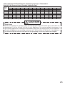
Vent Pipe Installation

16
No. of
Elbows
3
2
1
4
Max. Straight Vent Length**
3" (75mm) PVC or CPVC
Max. Straight Vent Length**
4" (100mm) PVC or CPVC
** Not including the concentric termination
16' (4.8m)
N / A
22' (6.6m)
28' (8.4m)
30' (9.0m)
N / A
36' (10.8m)
42' (12.6m)
Maximum Vent Length Adjustment Dip switches.
0
3
6
9
12
15
18
21
24
27
30
33
36
39
42
0.00
0.90
1.80
2.70
3.60
4.50
5.40
6.30
7.20
8.10
9.00
9.90
10.80
11.70
12.60
m 10 2 3ft
Vent length*** Elbows
0
1
2
3
4
5
6
7
8
9
10
11
12
13
14
N /A
N /A
N /A
N /A
N /A
N /A
N /A
N /A
N /A
N /A
N /A
N /A
N /A
N /A
N /A
Number of
pieces****
-5%
-5%
3
3
0%
3
3
4
4
4
4
4
4
4
4
4
4
4
3
3
0%
4
4
4
4
4
4
4
4
4
4
4
4
4
-3%
-3%
-3%
-3%
-3%
-5%
4
4
4
4
4
4
4
4
4
4” Pipe
<Maximum Vent Length and Reduced Input Congurations>
*** Refer to page 13 for 3" pipe Maximum Vent Length Adjustment Dipswitches table.
3
4
Short length using 4" (100mm) pipe
Long length using 4" (100mm) pipe
****Table assumes straight vent pieces are 3’ (0.9m) each.
Shorter or longer vent pieces may also be used up to the maximum
allowed vent length.
H
H
H
H
H
H
H
Hanger
Straps
3" (75mm) or
4" (100mm)
Intake*
Horizontal Vent Termination- 3" (75m) Concentric PVC/CPVC Termination
3" (75m
m
) or
4" (100m
m
)
Exhaust*
The concentric termination TWHHORCONC may be
shortened, but not lengthened from its original
factory supplied length.
The concentric termination may only be used
for horizontal terminations.
Terminate at least 12" (300mm) above grade or
above snow line.
Terminate at least 7' (2.1m) above a public walkway,
6' (1.8m) from the combustion air intake of any
appliance, and 3' (0.9m) from any other building
opening, gas utility meter, service regulator etc.
Terminate at least 3' (0.9m) above any forced air
inlet within 10' (3m), 1' (0.3m) below, 1' (0.3m)
horizontally from or 1' (0.3m) above any door,
window, or gravity air inlet into any building per
National Fuel Gas Code ANSI Z223.1/NFPA 54.
Slope the horizontal vent 1/4" upwards for every
12" (300mm).
Use a condensation drain if necessary.
In the Commonwealth of Massachusetts a carbon
monoxide detector is required for all side wall
horizontally vented gas fuel equipment.
Please refer to Technical Bulletin TB 010606 for full
installation instructions.
Slope vent
Upwards
* 4" (100mm) pipe requires the use of a reducing coupling
just prior to the termination.
H
H
H
H
3" (75mm) or 4" (100mm) PVC or CPVC pipe
may be used with the concentric termination.
Maintain the same vent pipe diameter from the
water heater ue to the termination.
Do not exceed the maximum vent lengths as
specied in this section.
When using 4" (100mm) pipe, it will be necessary
to use 4" (100mm) x 3" (75mm) reducing couplings
and a short section of 3" (75mm) pipe to connect to
the termination.
Use no more than a 6" (150mm) section of pipe to
make the connection between the reducing
couplings and the termination.
H
Install a securing strap to prevent movement of
the termination.
There must be a 1" (25mm) to 4" (100mm) clearance
between the outside wall and the air intake section
of the termination as illustrated on the left.
1" (25mm) to
4" (100mm)
Insert Bird Screen ***
in End of Termination
*** Not supplied with
water heater,
order separately.
Strap

Vent Pipe Installation
Horizontal Vent Termination- PVC/CPVC Materials Only
Intake and exhaust should face the same direction.
Intake and exhaust should keep the same
pressure zone.
2ft. Min
Interior View
Interior View Exterior View
Interior View Exterior View
1ft. Min1ft. Min
0
Insert the bird screen.
90° elbow vertical setting (downward).
0
Ensure at least 3ft (0.9m) or more distance between
the near edge of the air intake pipe or exhaust pipe
to the inside corner of a wall.
0
Ensure at least 2ft (0.6m) or more distance between
intake pipe and exhaust pipe.
The distance is measured at inside of pipe to inner
dimension.
0
Intake and exhaust should face the same direction.
Intake and exhaust should keep the same
pressure zone.
0
Insert the bird screen.
90° elbow vertical setting (downward).
0
Ensure at least 3ft (0.9m) or more distance between
edge of air intake pipe or exhaust pipe and corner wall.
0
Upper side is exhaust, lower side is intake.
The reverse connection is not allowed.
0
Ensure at least 1ft (0.3m) or more distance between
intake pipe and exhaust pipe.
The distance is measured at the outlets of
intake port (terminal) and exhaust port (terminal).
0
Intake and exhaust should face the same direction.
Intake and exhaust should keep the same
pressure zone.
0
Insert the bird screen.
90° elbow vertical setting (downward).
0
Ensure at least 3ft (0.9m) or more distance between
edge of air intake pipe or exhaust pipe and corner wall.
0
The side distant fr
om wall is intake, the side near the
wall is exhaust.
The reverse connection is not allowed.
0
Ensure at least 1ft (0.3m) or more distance between
intake pipe and exhaust pipe.
The distance is measured at inside of pipe to inner
dimension.
0
0
Exhaust
Intake
Exhaust Intake
1ft. Min
Exterior View
Exhaust
Exhaust
Intake
Intake
Exhaust Intake
3” Min
WARNING
If the distance between the air inlet and exhaust vent terminations is too short, the water heater
will draw in the exhaust gases through the intake. There is a risk of inadequate combustion air
for the water heater, increasing Carbon Monoxide (CO) emissions and noise due to vibration.
0
Termination elbows must be oriented vertically, pointing directly downward. Attempts to prevent
exhaust air from entering the air inlet by angling termination elbows in directions other than
directly downward will increase the risk of freezing.
0
Reversing the air intake and exhaust pipes is not allowed.
Carbon Monoxide (CO) emissions and noise due to vibration will increase.
3” Min
3” Min
5.9”
5.9”
5.9”
Do Not Use TWHHORHOOD as a vent termination unless there is at least 3ft. (0.9m) or more distance between the intake pipe and exhaust pipe.
Installations where 3ft (0.9m) distance cannot be met, use 90° elbows as the vent terminations as shown in the illustrations below.

Vertical Vent Termination- PVC/CPVC Materials Only
Firestop
Firestop/Support
Roof
Flashing
Storm
Collar
Hanger
Strap
Horizontal Vent Termination- PVC/CPVC Materials Only
Hanger
Straps
**1' (0.3m) Minimum
Slope vent
Upwards
**1' (0.3m) Minimum
* Not supplied with water
heater, order separately.
recommended, but not required.
Insert Bird
Screen* in
Each End
of Tee
Support
Insert Bird
Screen* in
End of 90
Elbow
Slope vent
Upwards
* Not supplied with water
heater, order separately.
**1' (0.3m)
Minimum
**1' (0.3m) minimum
recommended, but not required.
D
D
D
D
D
D
D
D
D
D
D
D
D
D
D
A tee, 90° elbow, or the TWHHORHOOD termination may be
used for the vent termination. It is not necessary to use bird
screens with the TWHHORHOOD termination.
Terminate at least 12" (300mm) above grade or above snow line.
Terminate at least 7' (2.1m) above a public walkway, 6' (1.8m) from
the combustion air intake of any appliance, and 3' (0.9m) from
any other building opening, gas utility meter, service regulator etc.
Terminate at least 3' (0.9m) above any forced air inlet within
10' (3m) , 4' (1.2m) below, 4' (1.2m) horizontally from or
1' (0.3m) above any door, window, or gravity air inlet into any
building per National Fuel Gas Code ANSI Z223.1/NFPA 54.
Slope the horizontal vent 1/4" upwards for every 12" (300mm)
toward the termination.
Use a condensation drain if necessary.
In the Commonwealth of Massachusetts a carbon monoxide detector
is required for all side wall horizontally vented gas fuel equipment.
Please refer to Technical Bulletin TB 010606 for full installation
instructions.
The TWHVERTCAP termination may be used
in place of elbows as the vertical vent termination.
Terminate at least 6' (1.8m) from the combustion air
intake of any appliance, and 3' (0.9m) from any other
building opening, gas utility meter, service regulator etc.
Enclose exterior vent systems below the roof line to limit
condensation and protect against mechanical failure.
When the vent penetrates a oor or ceiling and is not
running in a re rated shaft, a restop and support is
required.
When the vent termination is located not less than
8' (2.4m) from a vertical wall or similar obstruction,
terminate above the roof at least 2' (0.6m), but not
more than 6' (1.87m), in accordance with the National
Fuel Gas Code ANSI Z223.1/NFPA 54.
Provide vertical support every 3' (0.9m) or as required
by the vent pipe manufacturer's instructions.
A short horizontal section is recommended to prevent
debris from falling into the water heater.
When using a horizontal section, slope the horizontal
vent 1/4” upwards for every 12” (300mm) toward the
termination to drain condensate.
Exhaust
Intake
Exhaust
Intake
90 Elbow
SV Conversion Kit
Accessory
(#SV-CK-3)
90 Elbow
SV Conversion Kit
Accessory
(#SV-CK-3)
Inlet screen
Inlet screen
3” Min.
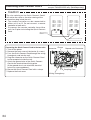
* Dip switch No.3 is turned on.
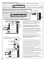
Vent Pipe Installation (When supplying combustion air from the indoors (SV, non-direct vent))
t%JTDPOOFDUQPXFSBOEUVSO0/EJQTXJUDIJGDPNCVTUJPOBJSXJMMCFTVQQMJFEGSPNUIF
indoors as illustrated to the right. Refer to page 31 for the location of the dip switch bank.
t
SV Conversion kit #SV-CK-3 is required for the air intake. The SV Conversion Kit
#SV-CK-3 is contained within both the Horizontal Installation Kit (TWHHORKIT)
and the Vertical Installation Kit (TWHVERTKIT).
'BJMVSFUPQFSGPSNUIFBCPWFTUFQTDPVMESFTVMUJOBàSFPSFYQMPTJPODBVTJOH
property damage, personal injury or death.
3FGFSUPUIFJOTUSVDUJPOTQSPWJEFEXJUIUIFDPOWFSTJPOLJUGPSBEEJUJPOBMEFUBJMT
WARNING
When installing this water heater in an area with a large amount of lint such as a commercial Laundromat,
direct-vent ("-DV") system must be used. The "-SV" configuration (using an SV conversion kit) is prohibited.
DANGER

19
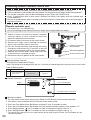
r1SPWJEFUXPQFSNBOFOUPQFOJOHTUPBMMPX
circulation of combustion air.
r.BLFFBDIPQFOJOHTRVBSFJODIFTJGUIFZ
provide indoor air, and 100 square inches for
outdoor air.
r*GUIFVOJUJTJOTUBMMFEJOBNFDIBOJDBMDMPTFU
QSPWJEFBNNDMFBSBODFJOGSPOUPG
the unit to the door.
r*GDPNCVTUJPOBJSXJMMCFQSPWJEFEUISPVHIB
duct, size the duct to provide 60 cubic feet of
fresh air per minute.
4VQQMZDPNCVTUJPOBJSUPUIFVOJUTBTQFSUIF/BUJPOBM'VFM(BT$PEF"/4*;
Combustion Air
Openings supplying indoor air
10" (250mm)
20" (500mm)
10" (250mm)
20" (500mm)
Provide adequate combustion air so as to not create negative pressure within the building.

20
Follow the instructions from the gas supplier.
Gas Type
The gas type indicated on the water heater rating plate (NG or LP) must match the type of gas being
supplied to the water heater.
Gas Conversions
If the gas type supplied does not match the gas type on the rating plate, obtain a replacement unit
with the proper gas type. If a gas type conversion must be made, there are conversion kits available
for some models. [The conversion kit shall be installed by an Electrolux authorized installer/servicer
in accordance with the manufacturer’s instructions and all applicable codes and requirements of the
authority having jurisdiction. The Electrolux authorized installer/servicer is responsible for the proper
installation of this kit. Improper installation of this kit will void the warranty.]
Meter
The gas meter must be sized properly for the water heater and other gas appliances to operate properly.
Select a gas meter capable of supplying the entire btuh demand of all gas appliances in the building.
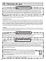
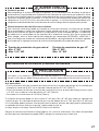
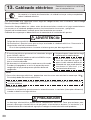
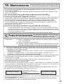
9.
Gas Piping
The guidelines and examples we have provided in this manual section are for reference only.
The sizing and installation of the gas system for this water heater, as with any gas appliance, is
the sole responsibility of the installer. The installer must be professionally trained to do such work
and must always follow all local and national codes and regulations. Gas line sizing calculations
must be performed for every installation. Please contact Electrolux Home Products, Inc. at 1-888-
360-8557 if you have any questions or concerns.
CAUTION
Regulators
Ensure that all gas regulators used are operating properly and providing gas pressures within the specied
range of the water heater being installed. Excess gas inlet pressure may cause serious accidents.
CAUTION
Pressure
Check the gas supply pressure immediately upstream at a location provided by the gas company.
Supplied gas pressure must be within the limits shown in the specications section with all gas appliances
operating. The inlet gas pressure must be within the range specied. This is for the purposes of input
adjustment. Low gas pressure may cause a loss of ame or ignition failure at other appliances in the home,
which may result in unburned gas in the home. Serious accidents such as re or explosion may result.
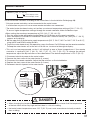
Measuring Gas Pressure
In order to check the gas supply pressure to the unit, a tap is provided on the
gas inlet. Remove the 9/32” hex head/Philips screw from the tap, and connect
a manometer using a silicon tube. Open up at least 2 xtures and hold in the
maximum manifold pressure button on the circuit board. Please call Electrolux
Home Products, Inc. for details.
NOTE* When checking the supply pressure, make sure to have all other gas appliances turned on
and running.
WARNING
Page is loading ...
Page is loading ...
Page is loading ...
Page is loading ...
Page is loading ...
Page is loading ...
Page is loading ...
Page is loading ...
Page is loading ...
Page is loading ...
Page is loading ...
Page is loading ...
Page is loading ...
Page is loading ...
Page is loading ...
Page is loading ...
Page is loading ...
Page is loading ...
Page is loading ...
Page is loading ...
Page is loading ...
Page is loading ...
Page is loading ...
Page is loading ...
Page is loading ...
Page is loading ...
Page is loading ...
Page is loading ...
Page is loading ...
Page is loading ...
Page is loading ...
Page is loading ...
Page is loading ...
Page is loading ...
Page is loading ...
Page is loading ...
Page is loading ...
Page is loading ...
Page is loading ...
Page is loading ...
Page is loading ...
Page is loading ...
Page is loading ...
Page is loading ...
Page is loading ...
Page is loading ...
Page is loading ...
Page is loading ...
Page is loading ...
Page is loading ...
Page is loading ...
Page is loading ...
Page is loading ...
Page is loading ...
Page is loading ...
Page is loading ...
Page is loading ...
Page is loading ...
Page is loading ...
Page is loading ...
Page is loading ...
Page is loading ...
-
 1
1
-
 2
2
-
 3
3
-
 4
4
-
 5
5
-
 6
6
-
 7
7
-
 8
8
-
 9
9
-
 10
10
-
 11
11
-
 12
12
-
 13
13
-
 14
14
-
 15
15
-
 16
16
-
 17
17
-
 18
18
-
 19
19
-
 20
20
-
 21
21
-
 22
22
-
 23
23
-
 24
24
-
 25
25
-
 26
26
-
 27
27
-
 28
28
-
 29
29
-
 30
30
-
 31
31
-
 32
32
-
 33
33
-
 34
34
-
 35
35
-
 36
36
-
 37
37
-
 38
38
-
 39
39
-
 40
40
-
 41
41
-
 42
42
-
 43
43
-
 44
44
-
 45
45
-
 46
46
-
 47
47
-
 48
48
-
 49
49
-
 50
50
-
 51
51
-
 52
52
-
 53
53
-
 54
54
-
 55
55
-
 56
56
-
 57
57
-
 58
58
-
 59
59
-
 60
60
-
 61
61
-
 62
62
-
 63
63
-
 64
64
-
 65
65
-
 66
66
-
 67
67
-
 68
68
-
 69
69
-
 70
70
-
 71
71
-
 72
72
-
 73
73
-
 74
74
-
 75
75
-
 76
76
-
 77
77
-
 78
78
-
 79
79
-
 80
80
-
 81
81
-
 82
82
-
 83
83
-
 84
84


Electrolux EN19WI30LS Installation guide
- Category
- Water heaters & boilers
- Type
- Installation guide
- This manual is also suitable for
Ask a question and I''ll find the answer in the document
Finding information in a document is now easier with AI
in other languages
Related papers
Other documents
-
SharkBite FIPDO123838Z Installation guide
-
-
SharkBite CPVCA1238Z Installation guide
-
LG 65UF950V User manual
-
Samsung AQ12VBLN Installation guide
-
LG Electronics DLEX3370R User guide
-
-
LG DLEX9000V Owner's manual
-
LG DLGX5001V Owner's manual
-