Page is loading ...

TRION 210
OWNER’S MANUAL
WARNING:
Read
Revision 2018-1-31
carefully and understand all ASSEMBLY AND OPERATION
INSTRUCTIONS before operating. Failure to follow the safety rules and other
basic safety precautions may result in serious personal injury.

“Danger” indicates an imminently hazardous situation which, if not avoided,
.
“Warning!” indicates a possible hazardous situation which, if not avoided, could
.
“Caution” indicates a possible hazardous situation which, if not avoided, may
.
“Note!” indicates a situation which implies a risk of impaired welding result
and damage to the equipment.
“Important!”
Utilisation for intended purpose only.
as defi
Safety signs.
pasted or painted cover.
Safety inspection.
regular intervals.
power sources.
Electric shock can kill. T
The input power circuit and machine internal circuits are also live
all metal parts touching the welding wire are electrically live. Incorrectly installed or
.
2

fl
AC welder with reduced open-load voltage.
.
fi
- IT and telecoms equipment
- IT and telecoms equipment
- W
-Mains supply
-W
-W
.
V
flame-resistant material (leather
fl
arc nor expose themselves to the arc rays or to hot spatter or material.
W
your health.
3

.
W
fi
supplied respirator.
W
confi
fi
fi
W
to prevent hazardous situations.
fire hazards or
overheat.
W
fl
position or in confined places.
when in a welding area.
fire. Remove
fi
.
Do not weld where fl
fl
atmosphere may contain fl
gasoline).
fl
Keep a fi
contact tip when not in use.
4

fi
flame.
gas cylinder.
fittings
condition.
All
fi
good condition.
cylinder valve outlet.
V
Hot parts can burn.
Flying metal or dirt can injure eyes. When welding, chipping, wire
flying metal. It can hurt your
eyes.
Noise can damage hearing. Noise can be from some working equipments or
Moving parts can injure.
.
fi
as drive rolls.
Have only qualifi
servicing and maintenance is fi .
5

duty cycle to use the machine.
Allow cooling period.
flow to unit.
.
fi
fication.
-T
6

î
î
peut entraî
Indique une situation qui implique un risque de perte de
fi fi
T
ûlures graves. Lorsque la machine est
fi î î fil et
fil de soudure sont
.
fi
É
fi
Connectez le câ
maintenance.
è é é
7

fil) semi-
T ûr
-
Alimentation secteur
Câ
Connectez le câ
â
â
Blindage
û
ûler les yeux et la peau.
T
fl
T
non infl
La soudure peut produire
8

.
Travailler dans un espace confi
.
T
fi fi
ûr.
Les étincelles de soudure et de coupe peuvent provoquer un incendie
ou une explosion. Lors de la soudure, assurez-vous que le circuit de
Assurez-vous que la zone est sûre avant toute soudure.
.
Connectez le câ
position ou dans des endroits confi T
fissures
fl
vapeurs infl
fi
pas ou ne les contourne pas.
9

É
.
fisant de personnes pour
T fixant sur un
.
Gardez une distance sû
toute autre source de chaleur flammes.
â
ç
çus
T
û
avec la main nue ou la peau.
ûlures.
fi
soudure.
.
10

înement.
fi
î
utiliser la machine.
.
T
mise en œuvre pour la certifi
-T
normes pour le Canada et les É
11

Please read and save these instructions. Read through this owner’s manual carefully before using product.
Protect yourself and others by observing all safety information, warnings, and cautions. Failure to comply
with instructions could result in personal injury and/or damage to product or property. Please retain
instructions for future reference.
12
Operating Instructions and Parts Manual
MIG WELDER
Description
The TRION 210 is a multi-process DC inverter
welder, with LCD screen. This unit uses 1~Phase
120V or 230V, 50/60HZ AC power. A 15 amp
time delay fuse or circuit breaker is
recommended. The TRION 210 series is ideal for
Do-It-Yourself projects or for light maintenance.
MIG weld carbon steel, stainless steel , AlMg and
AlSi.
Unpacking
1.1 Remove cartons, bags or Styrofoam containing the welder and
accessories.
1.2 Check the contents with the p
acking list below.
ITEM QTY.
tinu 1 redleW GIM retrevnI CD
scp1 nug GIM
scp1 pmalc htiw elbac gnidnuorG
Gas hose ф5.5
3m
tes1 launaM s’rotarepO

Operating Instructions and Parts Manual
MIG/MMA WELDER
1.3 After unpacking unit, inspect carefully for any damage that may have
occurred during transit. Check for loose, missing, or damaged parts. Shipping
damage claim must be filed with carrier.
Operating Instructions and Parts Manual
Specifications and Dimension
Description Specification
012 NOIRT ledoM
Input power V 120(110~130) 230(220~240)
Frequency Hz 50/60 50/60
Rated input current A 20 36
Rated input capacitance KVA 3.5 8.6
No-load voltage V 69 69
Rated working voltage V 18.5 24
MMA welding current A 10~70 10~180
LIFT Arc welding current A 10~90 10~180
MIG welding current A 40~90 40~200
Rated duty cycle % 40 20
Welding current(10min) A 40%@90 20%@200
10min/100% A 57 89
Efficiency η 85%
Power factor Cosφ 0.75
H ssalc noitalusnI
Enclosure protection IP 21S
Cooling type
Fan cooled
Dimension L×W×H cm 73*32*48
Weight kg 18
13

Operating Instructions and Parts Manual
MIG/MMA WELDER
Removing from carton
1.1 Remove cartons, bags or Styrofoam containing the welder and accessories.
1.2 Check the contents with the packing list below.
Factory standard:EN60974-1
Optional accessories:Protective mask、tip、welding wire
GROUNDING CABLE
Use earth clamp to connect earth cable with work piece
MIG GUN
The welding wire is driven through the welding cable and MIG gun to the work piece.
It is attached to the drive system.
POWER SWITCH
In the “OFF” position no power is being supplied
In the “ON” position power is supplied to the main transformer and control circuit
14
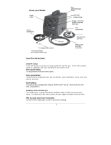
Know your Welder
Front Ctrl Panel
MIG Socket
Torch Polarity
Change Cable

Operating Instructions and Parts Manual
MIG/MMA WELDER
INPUT POWER CORD
The power cord connects the welder to the 120V/230 volt power supply. 14 amp
receptacle to supply power to the welder.
Torch Polarity Change Cable
To change the polarity of gun for kinds of core wire welding.
NAMEPALTE OF WELDER
The nameplate indicate the main electrical data of welder.
Front Ctrl panel
1. LCD: Shows all process from function selection to welding.
2. LEFT ADJUST KNOB: Allows user to adjust the current and wire feeding speed
accurately.
3. RIGHT ADJUST KNOB: Allows user to adjust the voltage accurately.
4. Home Key: Keep pressing home key, return to home page
5. Multi-function adjusting knob: For function selection; Press for confirming.
6. Return: Return to the previous step.
15
3
4
1 2
6
5

Operating Instructions and Parts Manual
MIG/MMA WELDER
Interface description
1. Multi-functions selection: Total 9 functions, 8 welding functions and 1 setting.
Adjusting multi-function knob for selecting, press for confirming
2. Output setup: Shows output connection under different welding mode, press
multi-function knob for confirming
3. Electrode/ Wire diameter selection:Adjusting multi-function knob to select
different electrode/wire diameter, press for confirming
16

Operating Instructions and Parts Manual
MIG/MMA WELDER
4. Material thickness: Adjusting multi-function knob to select different material
thickness, press for confirming
5. Welding display:
Shows all selected parameters.
a. Under MIG welding, user can set wire feeding speed and voltage. Adjusting
Multi-function knob to set electro-inductance, press the knob to progress basic
parameter setting.
Note:
Note 1. Basic parameter setting including:gas pre flow, slow wire feeding, gas post flow, operating, load and save
function. there is also spool gun function under Al welding
Note2: In the green range of current and voltage, it means recommended parameter.
b. Under TIG welding, user can set current parameter;
17

Operating Instructions and Parts Manual
MIG/MMA WELDER
c. Under Stick welding, user can set current, arc force parameter and hot start.
6. Setting interface: It shows language setting, units setting, light setting,
information and recover setting.
7. Alarm interface:It shows the machine is overloaded and the internal temperature
is too high. Weld output will turn off automatically but the fan will still be working.
When the internal temperature is decreased, the alarm interface will turn off and
the machine will be ready to weld.
18

Operating Instructions and Parts Manual
MIG/MMA WELDER
Installation
Outside Connection of the Machine
1. Power requirement
AC single phase 230V or 120V , 50/60HZ fused with a 15 amp time delayed fuse
or circuit breaker is required.
•High voltage danger from power source! Consult a qualified electrician for proper
installation of receptacle. This welder must be grounded while in use to protect
the operator from electrical shock.
• Do not remove grounding prong or alter the plug in any way. Do not use any
adapters between the welder’s power cord and the p
ower source receptacle.
Make sure the POWER switch is OFF when connecting your welder’s power cord
to a properly grounded 120V/230Vac, 50/60Hz, single phase, 14 amp power
source.
2. Extension cord
During normal use an extension cord is not necessary. It is strongly
recommended that an extension cord should not be used because of the voltage
19

Operating Instructions and Parts Manual
MIG/MMA WELDER
drop they produce. This drop in voltage can affect the performance of the welder.
If you need to use an extension cord it must be a #12 gauge cord at the smallest.
-Do not use an extension cord over 25 ft. in length.
3. Setting up the work piece
3.1 Welding positions
There are two basic positions, for welding: Flat and Horizontal. Flat welding is
generally easier, faster, and allows for better penetration. If possible, the work
piece should be posit
ioned so that the bead will run on a flat surface.
3.2 Preparing the Joint
Before welding, the surface of work piece needs to be free of dirt, rust, scale, oil
or paint. Or it will create brittle and porous weld. If the base metal pieces to be
joined are thick or heavy, it may be necessary to bevel the edges with a metal
grinder. The correct bevel should be around 60 degrees.
See following picture:
Based on different welding position, there are d
ifferent welding joint, see following
images for more information
20
/