Alpine PWE-58 Owner's manual
- Category
- Musical Instrument Amplifier
- Type
- Owner's manual

FOR
VEHICLE
USE
ONLY/
POUR
UNE
UTILISATION
A
t:INTERIEUR
D'UN
VEHICULE
UNIQUEMENT/SOLO
PARA
VEHlCULOS
PWE-58
COMPACT
POWERED
8"
SUBWOOFER
•
OWNER'S MANUAL
Please read this manual to maximize your enjoyment
of
the outstanding performance and feature capabilities
of
the equipment, then retain the manual for future
reference.
•
MODE
D'EMPLOI
Veuillez lire ce mode d'emploi pour tirer pleinement
profit des excellentes performances et fonctions de cet
appareil, et conservez-le pour toute
reference
future.
•
MANUAL DE
OPERACION
Lea este manual, por favor, para disfrutar al maximo
de las excepcionales prestaciones y posibilidades
funcionales que ofrece el equipo, luego guarde el manual
para usarlo como referencia en el futuro.
ALPINE
ELECTRONICS,
INC.
1-7,
Yukigaya-Otsukamachi,
Ota-ku
Tokyo
145-0067,
Japan
Tel.: 0570-006636
ALPINE
ELECTRONICS
OF
AMERICA,
INC.
19145 Gramercy
Place
Torrance, California
90501
U.S.A.
Tel.: 1-800-ALPINE-1 (1-800-257-4631)
ALPINE
ELECTRONICS
OF
AUSTRALIA
PTY.
LTD.
161-165
Princes
Highway,
Hallam
Victoria
3803,
Australia
Tel.: 03-8787-1200
ALPINE
ELECTRONICS
DE
ESPANA,
S.A.
Portal
de Gamarra 36, Pabell6n, 32
01013
Vitoria (Aiava).
APDO
133, Spain
Tel.:
945-283588
ALPINE
ELECTRONICS
GmbH
Wilhelm-Wagenfeld-Strase
1-3
80807
Munchen, Germany
Tel.: (089)-324-2640
ALPINE
ELECTRONICS
OF
U.K.,
LTD.
Alpine House Earlplace Business Park
Fletchamstead Highway,
Coventry CV4
9TW, United Kingdom
Tel.: (0845) 313-1650
ALPINE
ELECTRONICS
FRANCE
S.A.R.L.
98, Rue de
Ia
Belle
Etoile,
Z.l. Paris
Nord
II,
B.P.
50016,
95945 Roissy Charles de
Gaulle
Cedex, France
Tel.: (01)
4863-8989
.
ALPINE
ITALIA
S.p.A.
Viale
C.
Colombo
8,
20090
Trezza no
Sui
Naviglio
(MI), Italy
Tel.: 02-484781

ENGLISH
Introduction:
Please
read this
OWNER'S
MANUAL thoroughly
to
familiarize yourself with each control and function. We at
ALPINE
hope that your new
PWE-S8 will
give you many years of listening enjoyment.
In
case
of
problems when installing your
PWE-S8,
please contact your authorized
ALPINE
dealer.
CAUTION:
These controls are for tuning your system. Please consult your authorized Dealer for
adjustment.
~WARNING
This symbol means important instructions.
Failure to heed them can result
in
serious injury or death.
~CAUTION
This symbol means important instructions.
Failure to heed them can result
in
injury
or
property damages.
~WARNING
•
DO
NOT
OPERATE ANY
FUNCTION THAT
TAKES YOUR ATTENTION
AWAY
FROM SAFELY DRIVING
YOUR VEHICLE.
Any function that requires your prolonged attention should only be perfonned after coming to a
complete stop. Always stop the vehicle in a safe location before performing these functions. Failure to do so may result in
an accident.
•
KEEP THE
VOLUME
AT
A LEVEL
WHERE
YOU CAN
STILL
HEAR OUTSIDE NOISES
WHILE
DRIVING.
Excessive volume levels that obscure sounds such as emergency vehicle sirens
or
road warning signals (train crossings,
etc.) can be dangerous and may result in an accident. LISTENING AT LOUD VOLUME
LEVELS IN A CAR MAY
ALSO
CAUSE
HEARING DAMAGE.
•
DO
NOT
DISASSEMBLE OR ALTER.
Doing
so
may result in an accident, fire
or
electric shock.
• USE THIS
PRODUCT
FOR MOBILE 12V APPLICATIONS.
Use for other than its designed application may
result in fire, electric shock
or
other injury.
• USE
THE CORRECT AMPERE RATING WHEN REPLACING FUSES.
Failure to do so may result in fire or
electric shock.
•
DO
NOT
BLOCK VENTS
OR
RADIATOR PANELS.
Doing so may cause heat to build
up
inside and may result
in fire.
•
MAKE
THE
CORRECT
CONNECTIONS.
Failure to make the proper connections may result in fire or product
damage.
• USE ONLY IN VEHICLES WITH A 12
VOLT NEGATIVE
GROUND.
(Check
with your dealer if you are not sure.)
Failure to do so may result in fire, etc.
• BEFORE WIRING, DISCONNECT
THE
CABLE
FROM
THE
NEGATIVE
BATTERY
TERMINAL.
Failure to do so
may result in electric shock or injury due to electrical shorts.
•
DO
NOT
ALLOW CABLES TO BECOME ENTANGLED IN SURROUNDING OBJECTS.
Arrange wiring and
cables in compliance with the manual to prevent obstructions when driving.
Cables
or
wiring that obstruct or
hang
up
on places such as the steering wheel, gear lever, brake pedals, etc. can be extremely hazardous.
• DO NOT SPLICE INTO ELECTRICAL CABLES.
Never cut away cable insulation to supply power to other
equipment. Doing so
will
exceed the current carrying capacity of the wire and result in fire
or
electric shock.
• DO NOT
DAMAGE
PIPE OR WIRING
WHEN
DRILLING HOLES.
When drilling holes
in
the chassis for
installation, take precautions so as not to contact, damage
or
obstruct pipes, fuel lines, tanks or electrical wiring.
Failure to take such precautions may result in fire.
• DO NOT USE BOLTS OR NUTS IN
THE
BRAKE
OR STEERING SYSTEMS TO
MAKE GROUND
CONNECTIONS.
Bolts or nuts used for the brake or steering systems (or any other safety-related system),
or
tanks should
NEVER
be used for installations
or
ground connections. Using such parts could disable control of
the vehicle and cause fire etc.
• KEEP
SMALL OBJECTS SUCH AS BOLTS OR SCREWS
OUT
OF
THE REACH
OF
CHILDREN.
Swallowing
them may result in serious injury.
If swallowed, consult a physician immediately.
~CAUTION
•
HALT
USE IMMEDIATELY IF
A PROBLEM
APPEARS.
Failure to do so may cause personal injury
or
damage
to the product. Return it to your authorized Alpine dealer or the nearest Alpine Service
Center
for repairing.
• HAVE
THE
WIRING
AND
INSTALLATION DONE
BY
EXPERTS.
The wiring and installation
of
this unit requires
special technical
skill
and experience.
To
ensure safety, always contact the dealer where you purchased this
product to have the work done.
• USE SPECIFIED ACCESSORY PARTS
AND
INSTALL
THEM
SECURELY.
Be sure to use only the specified
accessory parts. Use
of
other than designated parts may damage this unit internally
or
may not securely install
the unit in place. This may cause parts to become loose resulting in hazards or product failure.
• ARRANGE THE WIRING
SO
IT
IS NOT CRIMPED OR PINCHED
BY
A
SHARP
METAL EDGE.
Route the
cables and wiring away from moving parts (like the seat rails) or sharp or pointed edges. This will
prevent
crimping and damage to the wiring.
If wiring passes through a hole in metal, use a rubber grommet to prevent
the wire's insulation from being cut by the metal edge
of
the hole.
• DO
NOT
INSTALL IN LOCATIONS WITH HIGH MOISTURE OR DUST.
Avoid installing the unit
in
locations with
high incidence of moisture
or
dust. Moisture
or
dust that penetrates into this unit may result in product failure.

SERVICE CARE
+ IMPORTANT NOTICE
This Amplifier has been type tested and found to
comply with the limits for a Class B computing device in
accordance with the specifications in
Subpart
J of Part
15
of
FCC Rules. This equipment generates and uses
radio frequency energy, and it must be
installed
and
used
properly in accordance with the manufacturer's
instructions.
+ For European Customers
Should you have any questions about warranty, please
consult
your store
of purchase.
+ For Customers in other Countries
IMPORTANT NOTICE
Customers who purchase the product with which this
notice is packaged, and who make this purchase
in
countries other than the United States of America and
Canada,
please contact your dealer for information
regarding warranty coverage.
SPECIFICATIONS
NOTE:
SERIAL NUMBER:
INSTALLATION
DATE
:
INSTALLATION TECHNICIAN:
PLACE
OF
PURCHASE:
+IMPORTANT
Please record the serial number of your unit in the
space provided here and keep it as a permanent
record.
The
serial number plate is located on the rear
of the unit.
• For product improvement, specifications
and
design are subject to change without notice.
ACCESSORIES
• Mounting Bracket..
..
.....
..
..........
..
............ . .
..
....... .. .. . . . . . . . . . .....
..
..
. .
..
. ........
....
.....................................
..
..
............................... 4
• Bracket Screws...................................... .
.
..
.......
..
..
. . . . . . . . .
..
.. . . .
..
. . .
..
. . .
..
.........
..
..
. . . . .. .. .... .. . . .
..
. . . ... . . .
..
......... .. . . .
..
...... . .........
...
. 8
•
Fuse
(15A)
.
......
..................
..
..
..
.
........
..
..
..................
......
..
..
...
....
.......
.................
......
..
..
......
.
........
.................
..
.
...
.
....
..
.
....
.
....
..
.
.......
.
..
. 1
• lnpuVPower Wire Harness ...
..
..........
....
........
..
.
..
.......................
..
.
..
...................................
..
....
...
....... ...................................... ....... 1
• Remote Bass Level Knob ........
..
........................
..
......
..
...
..
..................................
..
............
..
..................
..
.
..
..
...............
..
...
..
............. 1
• Velcro .
..
.
..
.................
..
............
....
..
..............
..
......................................................
..
..............
..
...
....
..
.................................................. 1
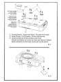
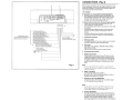
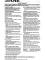
INSTALLATION (Fig. 1) & (Fig. 2)
&cAUTION
+ Caution on connection terminals/parts
• Keep electrically conductive objects away from the unit's terminals/parts (power terminals, fuses, speaker input
terminals, RCA connectors, etc.). Doing so prevents a possible short circuit and damage to the unit.
MOUNTING
1.
Attach the included mounting brackets to the PWE-S8 with the supplied screws. (See to
Fig.
1)
2.
Once the brackets are mounted to the PWE-SB. Place the subwoofer in the desired location within the
vehicle. Before securing with screws, check to make sure all screws can affix to a structurally solid surface
while avoiding vehicle wiring, components, etc. (See F
ig.
2)
Note: For securing the mounting brackets to the vehicle,
it
may
be
necessary to use longer screws (not
included) to accommodate carpet thickness, etc.
NOTE:
To
sec
ur
ely co
nn
ec
t the
ground
lead, use an already installed
sc
r
ew
on the metal
part
of
the ve
hicl
e (
mark
ed
*).
Be s
ur
e
this is a
go
od
ground
by
ch
ec
king continuity to the battery (-) termina
l.
As
much
as
po
ssible connect
all
equipme
nt
to the
sa
me ground point. These procedures will help eliminate noise.

®
c::r
Velcro
Apply
Velcro
(included)
d
to
the
flat
bottom
surface
of
the
remote
bass
level
knob
Appliquez
le
velcro
(inclus) sur
Ia
surface
plane inferieure
du
bouton
de
niveau des
basses
a
distance
Aplique velcro
(incluido) a
Ia
superficie plana
de
Ia
parte posterior
del
Interrupter
remoto
del
nivel
de
graves
CD
,,
I
'
I
......-a-
I
~
I
I I
I I
I I
I I
I I
I I
I I
I I
, I
~.
'T
CD
Mounting Bracket
I
Support
de fixation
I
Escuadra de montaje
(2)
Bracket
Screws
I
Vis de fixation
I
Tornillo autorroscante
®
Attachment Method Of
Remote Bass Level
Knob/
Methode
d'installation
du bouton de niveau des basses
a
distance/
Metoda
de fijaci6n dellnterruptor remota
del nivel
de graves
Fig.
1
*
<(>
Fig.
2

Speaker
Input
Leads
Fils
d'entree
des
haut-parleurs
5
Cables
de
entrada
de
Ia
bocina
2 1
....__,_
'f{'@
~•m•w•~
~·
~-~
@
.®.®.:~
~J=l
·
~
:
a "
!ICII<
1-Mtl
MA.ll
·~~~L~-
_
...,
_~
::;: @ 0
L_J
-
I
11
"'
c
'""
""'"
REM
POMRMOOE
I
1
11
1 I
~
~
I 4
I
eaker (White (+))
avant gauche
(B
lanc(+
))
ntero
izqu
i
erdo
(Bl
anco(+
))
aker
(White/Bla
ck
H)
8
avant
gauche
(Blanc/Nair
Hl
ntero
derecho
(B
l
anco
/N
egro(-))
peaker
(Gray (+))
Ground
Lead (Black)
c
avant
droit
(Gris (+))
Fit
de
mise
a Ia
ter
re (Nai
r)
Front
Left
Sp
Haut-parleur
Altavoz
dela
Front Left
Spe
Haut-parleur
Altavoz
dela
Front RightS
Haut-parleur
Al
tavoz
dela
F
ront
RightS
Haut-parleur
Altavoz
dela
ntero derecho (
Gri
s (
+))
Conducto
r
de
p
ue
s
ta
a tierra (Negro}
7
peaker
(Gray
/B
la
ck(
-
))
avant droit (Gris/Noir (-
))
ntero
izqu~o
{Gris/Negro
(-))
te
Tum-On Le
ad
(Bi
uei\'V
hite)
Remo
Fil de
Cable
mise
en
marche a distance (Bieu/Bianc)
para
encend
ido
rem
ota (Azul
/B
lanco)
ery
Lead
(Red) Batt
Fil
d
Cond
e
Ia
baHerie
(R
ouge
)
uctor
de
Ia
baterfa (Raja)
6
Fig.3
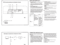
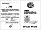
CONNECTIONS (Fig. 3)
Before making connections, be sure to turn the power off to a
ll
audio components. Connect the red battery lead from the amp
directly to the positive(+) terminal of the vehicle's batter
y.
Do
not connect this lead to the fuse block .
&cAUTION
+ Caution on connection terminals/parts
Keep electrically conductive objects away from the unit's
terminals/parts (power terminals, fuses, speaker output
terminals, RCA connectors, etc.). Doing so prevents a
possible short circuit and damage to the uni
t.
To prevent external
noise
from
entering
the
audio
sys
tem.
Locate the unit and route the leads at least
10
em (3-
15/16") away from the car harness.
Keep the battery power leads as far away from other leads
as possible.
Connect the ground lead securely to a bare metal spot
(remove any paint or grease if necessar
y)
of
the car
chassis.
You
r Alpine dealer knows best about noise prevention
measures so consult your deal
er
for furt
he
r information.
Input/Power
Connector
2 RCA
Input
Jacks
Connect these jacks to the line out leads on your headunit
using RCA
ex
tensi
on
cables (sold separately).
3 Fuse (15A)
USE ONLY THE CORRECT AMPERE
RATING
WHEN
REPLACING FUSES.
Failure to do so may result
in fire
or
electric shock.
4 Input/Power Wire Harness
5 Speaker
Input
Leads
These leads are input leads for use with head units not
equipped with preamp outputs. When not using the R
CA
Line Input connectors, you should connect these wires to
the speaker output leads of your head uni
t.
The PWE-SB
accepts input from
hi
gh power
or
standard power head
units.
Note:
Do not connect speaker leads togeth
er
or
to chassis ground.
u,e
either RCA line level or
sp
eaker level inp
ut
s.
Do not
co
nnect
ii:;:;::==
•
....__iili~
k
~
;
ii
:i;;
:;;;;~~ii;i
:
nr;;;iiii
~
iiii
~
:;l<~~~l!'.tH
4i:ll
a!t1ffi:iH¥.
ft.ii
5:Yff
both at the
same
time .
.
il:l
~
--llllfi
1ll
'--
lilil-ii'Jiil!liil!il
!l:ll
i!.
,
6
Battery
Lead (Red)
Connect battery lead directly to
BATI
+
Be sure to add a 15A fuse (sold separately) as close as
possible to the battery's (+)terminal.
7 Remote Turn-On Lead (Blue/White)
Connect this lead to the remote turn-on (positive trigge
r,
(+) 12V only) lead
of
your head unit.
Note:
If
using speaker input level
si
gn
al
jro
m the he
ad
uni
t,
remote
turn·on l
ead
connection is not necessary. Please make
sur
e
"Po
we
r Mode" button is
set
to
SPIN
(Button In).
8
Ground
Lead (Black)
Connect this lead securely to a clean, bare metal spot on
the vehicle's chassis. Verify this point to be a
tr
ue ground
by checking for continuity be
tw
een that point and the
negative (-) terminal
of
the vehicle's battery. Ground all
your audio components to the same point on the chassis to
prevent ground loops.

PWE-58
connection
panel/panneau
de
droite/panel
de
Ia
derecha
9
0
A
B
/
I
I
v@)@.@
00
1~
1
""'
O
50Hz
150Hz~
MAX
Q
0010
a'
©
0
Ct11
({)
CH2
POWER
SPEAKSl
I
II
:;:
·
L
~
J
H'UT
I
SUB
CJSPIN
ORE
..
REM
POWEI'IMOOE
I I
C D
Fig.4
PWE-58
Right
end
panel/panneau
de
droite/panel
de
Ia
derecha
I
I
I
I
CD
I
~®
-
I
-
I
PWE-88
®
®
\I/
@
I
(j)
®
Fig.S
~
SWITCH SETTINGS (Fig. 4)
9
Phase switch
oo
to
180°
Subwoofer output phase can be set to Subwoofer
Normal
oo (Button
Out)
or
Subwoofer Reverse
180°
(Button
In).
0 Crossover Frequency Adjustment Knob (LP FILTER)
Use this
control
to adjust
the crossover frequency between
50 to 150Hz.
A
Input
Gain Adjustment
Control
Note:
If
the Remote Bass Level Knob
will
be
connected
in
your system, make sure
to
rotate the knob fully clockwise
(set
to
"+")
before making
the input gain adjustment.
Set
the PWE-S8 input gain to the minimum position. Using
a dynamic CD as a source, increase the head unit
volume
until
the output distorts. Then, reduce the
volume
1 step (or
until
the output is no longer
distorted). Now, increase the
amplifier gain until
the sound from the speakers becomes
distorted. Reduce the gain
slightly so the sound
is
no
longer
distorted to achieve the optimum gain setting.
B
Power Indicator
Indication Color
Status
Solution
Blue
Amplifier
circuit is
normal
Amplifier
circuit Turn off the
is
abnormal.
An power
supply
electrical
short has and
eliminate
the
occurred,
or
supply
cause (replace
current is too high.
the 15A if
15A fuse may be
necessary). Then
blown.
turn on the unit
None
and verity that the
(LED is off)
LED
has
turned
on. If
it remains
off, turn off the
unit and consult
your
dealer.
Power
supply Use the correct
voltage is too high. power
supply
voltage.
CONNECTION CHECKLIST
(Fig. 5)
Please check your head unit for the conditions listed
below: (Fig.
4)
a.
The
head unit does not have a remote turn-on
or
power
antenna
lead.
b.
The
head unit's power antenna
lead
is activated
only
when
the radio is on (turns off in the tape
or
CD Mode).
c.
The
head unit's power antenna
lead
is logic level
output
(+)
5V,
negative trigger (grounding type),
or
cannot sustain
(+) 12V when connected to other equipment
in
addition to
the
vehicle's
power antenna.
If
any of the above conditions
exist, the remote turn-on
lead
of your PWE-SB must be
connected to a switched power source (ignition)
in
the
vehicle.
Be sure to use a 3A fuse as
close
as
possible
to this ignition tap. Using this connection method, the
PWE-SB
will
turn on and stay on as long as the ignition
switch
is
on.
C
SUB REM Bass Level
Input
Connect the Remote Bass
Level
Knob
(Included)
to adjust
the output
remotely.
This is not to
replace
appropriate gain
level
setting between the
amplifier
and
the head unit.
D Power Mode Button
Depending on your source unit. Two options to turn on the
PWE-S8.
Option
1:
- REM (Button Out).
Use this option when connecting the
Blue/White
Wire (remote turn-on wire).
Option2:
-
SP
IN
(Button
In).
Use
this option when connecting the
speaker input
leads.
Note:
For <Option 2> the
"Speaker
Level fnput System"
setting,
connecting
the
Remote
Turn-On
Lead is not required.
How
ever.
the
"SP fN"function
may not work depending on the signal
source
co
nn
ected.
In
such
a
case,
co
nnect
the
Remote
Turn-On
Lead
to
an
incoming power supply wire (accessory power)
in
the
ACC position and power mode set
to
REM (Button
fn)
.
E Remote Bass Level Knob
Allows
the user to adjust the
overall
bass
level
of the
subwoofer.
Turning the remote bass
level knob
towards(+)
increases
the
overall
subwoofer level,
while turning the bass
level
knob towards
(-)decreases
the
overall subwoofer
level.
(Note:
PWE-SB
can be used without connecting the
remote bass level knob. However, overall subwoofer level
cannot be adjusted from the listening position.)
If this is
objectionable,
a
SPST (Single Pole, Single Throw)
switch, in addition to the
3A
fuse mentioned above, may be
installed in-line
on the PWE-S8 turn-on
lead.
This switch
will
then be used to turn on (and off) the PWE-S8. Therefore, the
switch
should
be mounted so that is
accessible
by the driver.
Make sure the switch is turned off when the
vehicle
is not
running. Otherwise, the subwoofer
will
remain on
and
drain the
battery.
(j)
Blue/White
~
Power Antenna
Q)
Remote
Turn-On
Lead
@)
To
other Alpine
components' Remote
Turn-On
Leads
@
SPST
Switch
(optional)
@
Fuse (3A)
(J)
As close
as
possible
to the
vehicle's
ignition tap
@
Ignition Source

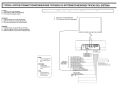
TYPICAL
SYSTEM
CONNECTIONS/CONNEXIONS
TYPIQUES
DU
SYSTEMEICONEXIONES
TIPICAS
DEL
SISTEMA
[English]
F
Head Unit, etc (sold separately)
G RCA Extension Cable (sold separately)
H
From Head Unit
Speaker Output
[Fran~ais]
F
Unite
principale, etc. (vendu
separement)
G
Cable
de rallonge RCA (vendu separement)
H
De Ia
sortie haut-parleur de
!'unite
principale
[Espaiiol]
F Unidad principal, etc. (se vende por separado)
G Cable de extension RCA (se vende por separado)
H
Desde
Ia
salida de
Ia
bocina de
Ia unidad principal
"
'
Note:
Power
Mod
e
button
must
be
set
to
REM
(Button
Out)
Remarque:
Le
bouton
Mo
de
d'a
/im
e
nt
at
io
n
doit
eire
r
eg
ie a
REM
(bouton
de
so
rtie
)
Nota:
El
bot6n
de
modo
de
enc
endido
d
ebe
esta
r en
REM
(bot6n
fu
e
ra
)
'
/
RCA
Input
System/Systeme d'entree RCA/Sistema
de
entrada RCA
F Head Unit, etc (sold separately)
F
G RCA Extension Cable (sold separately)
D D
=
(L) (
R)
/'~--
-.------------:--:--
--
----
----~
----
,"
..
. .
. .
. .
.
@
~®.:~~b.fi:lij!l
'
------.-
..!1
o.
-
-
-•~L•..:
' I "'"
@
0
L
J
-
-
:::
,C:.%
-
.
'
.
'
.
'
.
'
.
'
.
'
r-------•
..................
i
I
BUTTON
OUT
I
:SOUTON
DE
SORT
IE :
L
..
~~.!~~I-~~!l!!.
....
J
- Fr
ont
Left
Speaker
(White(+
))
Ha
ut
-parteur avant gauche (Blanc(+))
AJtavoz delantero izquierdo (Blanco(+))
Fro
nt
Left
Speaker
(White/Black(-
))
Haut
-
par1
eur
a
vant
gauc
he
(Bla
nc/Nair(-})
AJta
voz
delantem
derecho (Blanco/Negro (-
))
Il
l!
!
1111
I
I
4
Ground Lead (Black)
=
8
NOT USED
NON
UTILISE-
NOSE
UTILIZA
Fro
nt
Right Speaker (Gray(+))
Ha
ut
-pruteur
avant d
ro
it
(Gris
(+))
AJta
v
oz
de
lantero derecho (Gris
(+
))
F
il
de
mise
a
Ia
t
erre
(
No
ir
)
Cond
uct
or de
pues
ta a
tierra
(
Negro
)
Front Right
Speaker
(G
ray/Black(-))
Haut-
parl
eur
ava
nt
dro
it
(G
ri
s/Noir (-
))
Alta
voz
de
l
antero
i
zqu
i
erdo
(Gris/Negro
(-
))
- Remote T
um-Qn
Lead
(Bi
ue!Nh
ite)
7
F
il
de
mi
se
en
marche
a
di
stance
(Bi
eu/B
i
anc
)
'---------------------
C~a
~b!
le~pa
~
rn
~
~~~~ido~rern
~
o~to~(~
~u
~~~
l~an
~co~
)
________
__)
Battery Lead
(Red)
F
il
de
Ia
batterie (Rouge)
Co
ndu
ctor
de
!a
bateria
·
(Roto)
3".
6

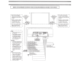
Speaker Level lnput/Systeme
d'entree de niveau
de
haut-parleur/Sistema
de entrada a
nivel
de bocina
F
------------
,
'
1 •
Note:
Connect
to
each
speaker
1
Left
Speaker
1
lead
(splice)
without
breaking
the
1
Haut-parleu
r
de
gauche
connection
between
the
headunit
and
Boc
i
na
izquier
da
the
speaker.
1
Q
*
Remarque : Connectez
chaque
jil
de haut-parleur sans briser
.+ll-
la
connexion entre l 'unite
..
....
..
.
principale et le haut-parl
eur.
1
••••
·~;::
••
H
Right
Speaker
Haut-pa
rl
eur
de
droite
Bocina
derecha
Q
------------
,
'
1
*
Note
:
Con
nec
t
to
each
s
peaker
1
1
lea
d
(splice)
without
breaking
the
1
connectio
n
between
the
headun
it
and
the
sp
eake
r.
···---0~d-
H
•
-,
'
:~-.::
••
11'_.
)
I
*
Remarque :
Connectez
chaque
jil
de haut-parl
eu
r sans briser
Ia
connexion entre l
'unite
principale et le haut-parleur.
*Nota:
Conecte a cada conductor
de
la
bocina (empalme) sin
romper
la
conexion entre
la
unidad principal
y
la
boci
na.
I·······..
__
...
(
.l
.~./
~-·····
;::::_:_.IJ"
l
I.
··········'
f-11-rr-
..,--
---..-,--tl--,-.,----,;,----,o;-------..
---,,.,;!:o!;{·•
••
~
1'_...
~······
0
L.....J
•••••••••
J
*Nota:
Conecte
a cada conductor
de
Ia
bocina (empalme) sin
romper
la
conexion entre
la
unidad principal
y
la
boc
in
a.
,_---------
__
,
/
Note:
'
I
Power
Mode
button
must
be
set
to
SPIN
(Button
In)
When
using
speaker
level
inputs,
LEFT
and
RIGHT
are
summed
to
a
MONO
signal
,
therefore
is
recommended
to
co
nn
ect
both
LEFT
and
RIGHT
input
s
ig
na
ls
for
proper
voltage
lev
el.
Remarque:
Le
bouton
Mode
d'alimenta
tio
n
doit
etre
regie
a
SPIN
(bouton
d
'e
ntn!e)
Lorsque
vous
utilise
z
les
e
ntrees
de
haut
-
parleur.
GAUCHE
et
DROIT£
sont
r
eg
roupes
pour
offrir
un
signal
MONO.
De
ce
fait,
il
est
recommande
de
connecte
r
les
signaux
d'entree
GAUCHE
et
DROIT
au
niveau
de
tension
appro
prie.
Nota:
'
El
bot6n
de
modo
de enc
end
ido
debe
estar
en
SP
EN
(boton
dentro)
Cuando
se
usan
las
entradas
a
nivel
de
bocina,
IZQUIERDA
y
DERECHA
se
agregan
a
una
senal
MONO,
por
lo
tanto
,
se
recomienda
c
onectar
am
bas
seiiales
de
entrada
IZQU!ERDA
y
DERECHA
para
el
nivel
correcto
de
vol
taj
e.
/
''
''
''
''
''
r....................
&
................... ,
:
BUTTON
IN
I
:BOUTON
D'ENTREE
:
L~~~~-~~~~~--j
F
ro
nt
Left
Speaker
(White
(+))
Haut-parleur
avant gauche
(Bla
nc(+
))
Altavoz delantero izquierdo
(Blanco
(+
))
Front Len
::;peaker (Whiter.,la
ck
(-
))
Haut-parleur
avant
gauche {
Bianc
/
No
ir
(-))
Altavoz delantero derecho (Blanco/Negro(-))
Front Right Speaker (Gray (
+))
Haut-parleur avant
dro~
(Gris
(+
))
Altavoz
delantero derec
ho
(Gris
(
+)
)
Front Rig
ht
Speaker
(Gray/Bl
ack
(-))
Haut-parleur
avant
dro~
(Gris!Noir
(-))
AHavoz
delantero
izquierdo (Gris!Negro (-))
NOT
USEQ {
Remote
Tum-On
Lead (BiuetWhite)
NON
UTILISE
Fil
de
mise en marche
a
dis
tance (Bieu/Bianc)
NO
SE
UTILIZA
Cable
para encendido remoto
(Azul/Blanco)
Battery Lead (Red)
Fil
de
Ia
batterie (Rouge)
_ Conductor
de
Ia
bateria (Rojo)
'3'"'
6
Ill! I
IIII
4
I I
8
Ground Lead
(Black)
~
Fil
de
mi
se
A !a
terre
(No
i
r)
Conductor
de
puesta
a
tierra
(Negro)
,
____________
,

PWE-58
8
..
COMPACT POWERED SUBWOOFER
CAISSON
DE
GRAVES ALIMENTE
DE
8 PO
Page is loading ...

WE
58
8" COMPACT POW
CAISSON
DE
GRAV~~ED
SUBWOOFER
ALIMENTE
DE
8
PO
e
IO
Innovation
Driving
Mobile
M
d.

PWE-58
8
..
COMPACT POWERED SUBWOOFER
CAISSON
DE
GRAVES ALIMENTE
DE
8
PO
4 58043 544950

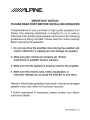
IMPORTANT NOTICE!
PLEASE
READ
FIRST BEFORE
INSTALLING SPEAKERS
Congratulations on your purchase of high quality speakers from
Alpine. Your listening satisfaction is important to us.
In
order to
maximize and maintain peak speaker performance the
following
guidelines are being provided.
Please
read this notice carefully
before operating the speakers.
1.
Do
not
over-drive the amplifier. Over-driving the
amplifier
will
result
in
distortion
or
clipping
and can damage any speaker.
2.
Make sure gain
controls
are properly set. (Follow
instructions
in
amplifier
owner's manual.)
3.
Make sure that the speaker is properly rated
for
the
amplifier.
4.
Make sure that volume, bass, treble,
equalization
or
crossover
settings
do
not
cause the
amplifier
to
over-drive.
Failure to follow
these guidelines may
result
in
burned or damaged
speaker voice
coils
which will
void your warranty.
If further assistance is necessary,
please
contact your
Alpine
authorized
dealer.
68-00493Z64-A (Y)

Thank you for choosing Alpine for your car audio equipment needs. Our goal is to
produce the best audio/video/navigation products in the world and hope your
expectations are met.
Please take a moment to protect your purchase by registering your product now at
the following address: www.alpine-usa.com/registration.
You
will be informed of
product and software updates (if applicable), special promotions, and news about
Alpine.
Also, by registering your product, you can enter for a chance to win prizes!
We look forward to continue serving you
in
the future.
Sincerely,
The Alpine Team
French
Nous vous remercions d'avoir porte votre choix sur un
equipement audio automobile Alpine. Notre principal
objectif est de fabriquer les meilleurs produits audio,
video et de navigation au monde afin de repondre aux
exigences de nos clients.
Veuillez prendre quelques instants pour securiser
votre achat
en
enregistrant votre produit a l'adresse
suivante: www.alpine-usa.com/registration. Vous
serez informe(e) des nouveaux produits, mises
a
jour
logicielles (le cas echeant), promotions speciales et
informations concernant Alpine.
Lors de !'enregistrement de votre produit, vous
pouvez vous inscrire et obtenir une chance de gagner
des
prix!
Nous esperons que nos produits vous donneront
entiere satisfaction.
Cordialement,
L.:equipe
Alpine
Spanish
Agradecemos que haya elegido a Alpine como
su
proveedor de equipo de audio para
su
vehfculo.
Nuestro objetivo
es
fabricar los mejores productos
de
audio, video y navegaci6n del mundo y esperamos
poder cumplir con sus expectativas.
Para proteger su compra le pedimos que se tome
unos mementos para registrar su producto en Ia
siguiente direcci6n: www.alpine-usa.com/registration
Recibira informacion sobre novedades del producto,
actualizaciones
de
software (si
su
producto lo
requiere), promociones especiales y noticias sobre
Alpine.
Ademas, si registra su producto, tendra
Ia
posibilidad
de
entrar a un sorteo para ganar diversos premios.
Esperamos poder tener
Ia
oportunidad de seguir
ofreciendole otros productos en el futuro.
Atentamente,
El equipo
de
Alpine
Page is loading ...

-
,..
-~
;r:,
.
.
~
·
--;.-_·-
..
...
-
,.
1
~;a;:~~~-~;~=~~=~::~=~!~r:-·r~jarfl
.·
dedieatedto
·
qyal~
;
cr•ft~-
···
·
.
·
·
···
;
you
flaY@
any
questl~.
'
l?~
•..
•
::::
-
_-;-
..
.- '·1:·
,;:_··
· ·
:~
ev,ltfQJJ
~:
c~ftEI.l:
..
. ·
·.·
'.
.~·.·.'
..
.
:.
·
>>.
~~
:i·>>:\')
·
.:
t/·.;
Thisw~rran~y
:
onty
·
coverstlleotfgfnar
·
~~
:·
()f
·
·~
·
produd,
\I'JhO
-
tnust
.
reside
.
1ft
the
·
united
s•~·
~
~~t.t6
Ateo-
.
or
Canada.
•WHAl:IS
COVERED:
.
This
Warranty
cowrs
defects
m
·.
matertals
·or
workmanship
(parts
·and
labor)
in
the
prod~t.
•WHAT
aS
NOT
COVERED:
This
Warranty
dOes
not
cover
the
fOllOWing:
Q)
Damage
·
occurring·
during
·
shipment·
of
fhe·
product
to
Alpine for-
repair (claims
must be
presented
to
the
·
carrier).
(%)
Damage caused
by
accident
or
abuse,
including
burned
voice
coils
caused
by
over-driving the speaker(amplifier
level
is
turned
up and driven into.
distortion·
or clipping).
Speaker mechanical failure
(e.g. punctures, tears or
rips).
Cracked or damaged
LCD
panels. Dropped or
damaged hard drives.
@
Damage caused
by
negligence,
misuse, improper
operation or failure to follow instructions contained
in
the Owner's
manual..
. @
Damage caused
by
act of
God,
including without
limitation, earthquake, fire,
flood,
storms or other acts of
nature.
Any cost or expense
related to the removal or rein-
stallation of the product.
~
Service
performed
by
an unauthorized person,
com·
pany
or association.
@
Any
product
Which
has the
serial
number defaced,
altered or
removed.
(j)
Any product which has been adjusted, altered or
modified without Alpine's consent.
<8)
Any product not distributed
by
Alpine within
·the. \Jnited
States,
Puerto Rico or
Canada. ·
®
Any
product not purchased from
an
Authorized
Alpine
·
Dealer.
e HOW TO OBTAIN
WARRANTY
SERVICE:
<D
You
are
responsible
for
delivery
of the product to
an
Authorized
Alpine
Service
Center or Alpine
for repair
and for payment of any
initial
shipping charges.
Alpine
will,
at its option, repair or
replace
the product with a
new
or reconditioned product without charge.
If
the
repairs are covered
by
the
warranty,
and if the product
was
shipped to
an
Authorized
Alpine Service Center
or
Alpine, Alpine will
pay
the return shipping charges.
<2)
You
should provide a
detailed
description of the
problem(s) for which service
is
required.
··
;··
®
v~
~~t
;.
$upp1~
:
pR)OtO,~y()Or
:
PU,re,•se
·
ot
tt1$~f6d~
f
··
®.
y~
·
must
·
~~ge
.....
::
pnxiuotsequr~ly
.
l()av~
·"
d~
..
;:
···
·
dUrillg
;
~~~To
_
~n
.
t
:
l9s(~ges
it
iS
:'·.·~
'.•:
·.,
..
:·
. · .. ·:.· ·
~~e~
:
tq
.
Wl,$
:
·
~
oarrifJr
lhafprovides ·a.
t~inQ
i·
·
sel'¥ice~
·
•HCw
····.
we
..
w...rt
·
·.a~o
··
wARRANraes:
·
..
..
.
..
.
·.·
.
..
···
..
·•.
•
..
.•. · .•.
.•.
...••..
.
·•.·
•:::
.••
:.··.
'
..
'
ANY
~M~LIEQWA~~~S
.
I~l..UI)fNG
F~TNESS
FGR
'.
'.
~se
·
AND
'
MeRCHANTASILJTV
..
AAE
LIMITED IN
.
.
DUf:tATtON
-
'f()
'
TJ-tE
·.PERiOD
····
oFTt-fi
·EXPRESS
.. ··
..
·
.•.
WARRAtfty.
·
sET
·
FORTH
~
AB()VEANDNOPERSONIS
• ·
AUfHOAtZEP
tO
ASSUME
FoR
·
A~PtNE
ANY
OTHER
~tABILtTV
IN
.
CONNECT10N
WtTH
THE.
SALE
OF
THE
PAQQ\Jet~
.
•
•HOW
We
PCLUDE
'CERTAIN DAMAGES:
:ALPINE
EXPRESSLY
DISCLAIMS LIABILITY
FOR
INCIDENTAL
AND
CONSEQUENTIAL
DAMAGES
CAUSED
BY
THE
PRODUCT.
THE
TERM
"INCIDENTAL
DAMAGES"
REF=ERS
TO
EXPENSES OF TRANSPORTING
THE
PRODUCT
TO
THE
ALPINE SERVICE
CENTER,
LOSS
OF
THE
ORIGINAL PURCHASER'STIME,
LOSS
OF
THE
USE
OF
THE
PRODUCT,
BUS
FARES,
CAR
RENTALS
OR
OTHERS COSTS
RELATING
TO
THE
CARE
AND
CUSTODY
OF
THE
PRODUCT.
THE
TERM
"CONSEQUEN-
TIAL
DAMAGES"
REFERS
TO
THE
COST
OF
REPAIRING
OR
REPLACING
OTHER
PROPERTY
WHICH
IS
DAMAGED
WHEN
THIS
PRODUCT
DOES NOT
WORK
PROPERLY.
THE
REMEDIES
PROVIDED
UNDER
THIS
WARRANTY
ARE
EXCLUSIVE
AND
IN
LIEU
OF
ALL
OTHERS.
eHOW
STATE/PROVINCIAL
LAW
RELATES TO
THE WARRANTY:
This Warranty gives
you
specific
legal
rights, and
you
may
also
have
other rights which vary
from
state to state and
province to province.
In
addition, some states/provinces do
not
allow limitations
on
how
long
an
implied
warranty
lasts,
and
some do not
allow
the
exclusion
or
limitation
of
incidental or consequential damages. Accordingly,
limitations
as to these matters contained herein
may
not apply to
you.
eiN
CANADA ONLY:
This Warranty
is
not valid
unless your
Alpine
car audio
product
h~s·
been installed
in
·your vehicle by
an
Authorized
InstallatiOn
·
Center,
. and this. warranty stamped upon
installation
by
the
installation
center.
e HOW TO
CONTACT
CUSTOMER SERVICE:
Should
the product require service, please
call
the
following
number for your nearest Authorized
Alpine Service
Center.
CAR
AUDIO
NAVIGATION
1-&GO-ALPINE-1
(1-800·257-4631)
1-888-NAV-HELP (1-888-628-4357)
Or visit our website
at;
http://www.alpine-usa.com
ALPI~E
ELECTRONICS
OF
AMERICA, INC.,
19145 Gramercy
Place,
Torrance,
California 90501,
U.S.A.
ALPINE ELECTRONICS OF
CANADA,
INC.,
777
Supertest
Road,
Toronto,
Ontario
M3J
2M9,
Canada
Do
not
send
products to these addresses.
Call the
toll free telephone number or visit the website to .locate
a service center.
-
 1
1
-
 2
2
-
 3
3
-
 4
4
-
 5
5
-
 6
6
-
 7
7
-
 8
8
-
 9
9
-
 10
10
-
 11
11
-
 12
12
-
 13
13
-
 14
14
-
 15
15
-
 16
16


Alpine PWE-58 Owner's manual
- Category
- Musical Instrument Amplifier
- Type
- Owner's manual
Ask a question and I''ll find the answer in the document
Finding information in a document is now easier with AI
in other languages
- français: Alpine PWE-58 Le manuel du propriétaire
Related papers
-
Alpine SWD-1600 User manual
-
Alpine PWE-S8 User manual
-
-
Alpine SPR-50 Installation guide
-
Alpine SPR-60C Installation guide
-
Alpine SPR-60 Installation guide
-
-
Alpine SWE-1000 Owner's manual
-
-
Other documents
-
Lanzar Car Audio AQTB8 User manual
-
 Mariner Speaker AQTB8 User manual
-
Kenwood KSC-WD250 User manual
-
Alpha Northern PWE Series Technical Manual
-
-
-
Kicker 19417165 Owner's manual
-
Henny Penny HCS-2 Operating instructions
-
-
