KitchenAid KESK901SSS User manual

Category
Ovens
Type
User manual

This manual is also suitable for

INSTALLATION INSTRUCTIONS
30" (76.2 CM) FREESTANDING AND SLIDE-IN
ELECTRIC RANGES
INSTRUCTIONS D'INSTALLATION DE
CUISINIÈRES ÉLECTRIQUES AUTOPORTANTES
OU COULISSANTES DE 30" (76,2 CM)
Table of Contents/Table des matières.............................................................................2
W10246119C
2
TABLE OF CONTENTS
RANGE SAFETY .............................................................................2
INSTALLATION REQUIREMENTS................................................3
Tools and Parts ............................................................................3
Location Requirements................................................................3
Electrical Requirements - U.S.A. Only.........................................5
Electrical Requirements - Canada Only.......................................6
Countertop Preparation ...............................................................7
INSTALLATION INSTRUCTIONS..................................................7
Unpack Range..............................................................................7
Measure for Proper Height...........................................................7
Adjust Leveling Legs....................................................................8
Install Anti-Tip Bracket.................................................................8
Electrical Connection - U.S.A. Only.............................................9
Verify Anti-Tip Bracket Location ................................................14
Level Range................................................................................14
Complete Installation .................................................................14
Moving the Range......................................................................14
ANTI-TIP BRACKET TEMPLATE ................................................24
TABLE DES MATIÈRES
SÉCURITÉ DE LA CUISINIÈRE ...................................................16
EXIGENCES D'INSTALLATION...................................................16
Outillage et pièces......................................................................16
Exigences d'emplacement.........................................................17
Spécifications électriques ..........................................................20
Préparation du plan de travail....................................................20
INSTRUCTIONS D'INSTALLATION.............................................20
Déballage de la cuisinière ..........................................................20
Mesures pour une hauteur appropriée ......................................21
Ajuster les pieds de nivellement.................................................21
Installation de la bride antibasculement ....................................21
Vérification de l'emplacement de la bride antibasculement......22
Réglage de l'aplomb de la cuisinière.........................................23
Achever l’installation ..................................................................23
Déplacement de la cuisinière.....................................................24
GABARIT POUR LA BRIDE ANTIBASCULEMENT....................24
RANGE SAFETY
You can be killed or seriously injured if you don't immediately
You
can be killed or seriously injured if you don't
follow
All safety messages will tell you what the potential hazard is, tell you how to reduce the chance of injury, and tell you what can
happen if the instructions are not followed.
Your safety and the safety of others are very important.
We have provided many important safety messages in this manual and on your appliance. Always read and obey all safety
messages.
This is the safety alert symbol.
This symbol alerts you to potential hazards that can kill or hurt you and others.
All safety messages will follow the safety alert symbol and either the word “DANGER” or “WARNING.”
These words mean:
follow instructions.
instructions.
DANGER
WARNING
WARNING
Tip Over Hazard
A child or adult can tip the range and be killed.
Connect anti-tip bracket to rear range foot.
Reconnect the anti-tip bracket, if the range is moved.
Failure to follow these instructions can result in death or serious burns to children and adults.
3
INSTALLATION REQUIREMENTS
Tools and Parts
Gather the required tools and parts before starting installation.
Read and follow the instructions provided with any tools listed
here.
Tools needed
Parts supplied
Check that all parts are included.
Anti-tip bracket must be securely mounted to subfloor.
Thickness of flooring may require longer screws to anchor
bracket to subfloor. Longer screws are available from your
local hardware store.
Parts needed
If using a power supply cord:
A UL listed power supply cord kit marked for use with ranges.
The cord should be rated at 250 volts minimum, 40 amps or
50 amps that is marked for use with nominal 1³⁄₈" (3.5 cm)
diameter connection opening and must end in ring terminals
or open-end spade terminals with upturned ends.
A UL listed strain relief.
Check local codes. Check existing electrical supply. See
“Electrical Requirements” section.
It is recommended that all electrical connections be made by a
licensed, qualified electrical installer.
Rear Filler Strip (optional)
The rear filler strip may be used to fill a gap between the rear of
the slide-in cooktop and the wall in a freestanding cutout.
Please reference the “Assistance or Service” section of the Use
and Care Guide to order.
Black - W10113902A
White - W10113903A
Biscuit - W10113904A
Location Requirements
IMPORTANT: Observe all governing codes and ordinances.
It is the installer’s responsibility to comply with installation
clearances specified on the model/serial rating plate. The
model/serial rating plate is located inside the oven door on
the right-hand side oven door trim.
The range should be located for convenient use in the
kitchen.
To eliminate the risk of burns or fire by reaching over heated
surface units, cabinet storage space located above the
surface units should be avoided. If cabinet storage is to be
provided, the risk can be reduced by installing a range hood
or microwave range hood combination that projects
horizontally a minimum of 5" (12.7 cm) beyond the bottom of
the cabinets.
Cabinet opening dimensions that are shown must be used.
Given dimensions are minimum clearances.
The floor anti-tip bracket must be installed. To install the anti-
tip bracket shipped with the range, see “Install Anti-Tip
Bracket” section.
Grounded electrical supply is required. See “Electrical
Requirements” section.
IMPORTANT: To avoid damage to your cabinets, check with your
builder or cabinet supplier to make sure that the materials used
will not discolor, delaminate or sustain other damage. This oven
has been designed in accordance with the requirements of UL
and CSA International and complies with the maximum allowable
wood cabinet temperatures of 194°F (90°C).
Tape measure
Flat-blade screwdriver
Level
Hammer
Hand or electric drill
Wrench or pliers
Marker or pencil
Masking tape
¼" nut driver
⁵⁄₁₆" nut driver
¹⁄₈" (3.2 mm) drill bit (for
wood floors)
³⁄₁₆" (4.8 mm) carbide-tipped
masonry drill bit (for
concrete/ceramic floors)
A. Anti-tip bracket
B. Plastic anchors (2)
C. #10 x ¹⁄₂" screws (2)
A
B
C
A. Rear filler strip
B. Countertop
C. Countertop cutout
B
A
B
C
4
Mobile Home - Additional Installation Requirements
The installation of this range must conform to the Manufactured
Home Construction and Safety Standard, Title 24 CFR, Part 3280
(formerly the Federal Standard for Mobile Home Construction
and Safety, Title 24, HUD Part 280). When such standard is not
applicable, use the Standard for Manufactured Home
Installations, ANSI A225.1/NFPA 501A or follow local codes.
In Canada, the installation of this range must conform with the
current standards CAN/CSA-A240-latest edition, or local codes.
Mobile home installations require:
When this range is installed in a mobile home, it must be
secured to the floor during transit. Any method of securing
the range is adequate as long as it conforms to the standards
listed above.
Four-wire power supply cord or cable must be used in a
mobile home installation. The appliance wiring will need to be
revised. See “Electrical Connection” section.
Product Dimensions
Freestanding Range
*Range can be raised approximately 1" (2.5 cm) by adjusting
the leveling legs.
**When installed in a 24" (61.0 cm) base cabinet with
25" (63.5 cm) countertop; front of oven door protrudes
1" (2.5 cm) beyond 24" (61.0 cm) base cabinet.
Slide-in Range
*Range can be raised approximately 1" (2.5 cm) by adjusting
the leveling legs.
**When installed in a 24" (61.0 cm) base cabinet with
25" (63.5 cm) countertop; front of oven door protrudes
1³⁄₄" (4.4 cm) (2³⁄₁₆" [5.5 cm] on models KERS807XSP and
KESS907XSP) beyond 24" (61.0 cm) base cabinet.
A. 5³⁄₄" (14.6 cm)
B. 30" (76.2 cm)
C. 41³⁄₄" (106.0 cm) overall
height with leveling legs
screwed all the way in*
D. 36" (91.4 cm) cooktop trim
height with leveling legs
screwed all the way in*
E. 30" (76.2 cm)
F. 27¹⁄₄" (69.2 cm) max. from
handle to standoff at back of
range**
G. Model/serial number plate
(located on the right-hand side
oven door trim)
A
B
C*
D*
E
F**
G
A. 30¹¹⁄₁" (77.6 cm)
B. 35⁵⁄₈" (90.5 cm) height to
underside of cooktop edge
with leveling legs screwed
all the way in*
C. Model/serial number plate
(located on the right-hand
side oven door trim)
D. 30" (76.2 cm)
E. 27¼" (69.2 cm)
(27
¹¹⁄₁₆
" [70.3 cm] on
models KERS807XSP
and KESS907XSP) from
handle to standoff at
back of range**
F. 23" (58.4 cm) countertop
notch to rear of cooktop
C
B*
A
D
E**
F
5
Cabinet Dimensions
Cabinet opening dimensions shown are for 25" (64.0 cm) countertop depth, 24" (61.0 cm) base cabinet depth and 36" (91.4 cm)
countertop height.
IMPORTANT: If installing a range hood or microwave hood combination above the range, follow the range hood or microwave hood
combination installation instructions for dimensional clearances above the cooktop surface.
Freestanding Range
A freestanding range may be installed next to combustible walls
with zero clearance.
Slide-in Range
NOTE: 24" (61.0 cm) minimum when bottom of wood or metal cabinet is covered by not less than ¹⁄₄" (0.64 cm) flame retardant
millboard covered with not less than No. 28 MSG sheet steel, 0.015" (0.4 mm) stainless steel, 0.024" (0.6 mm) aluminum or
0.020" (0.5 mm) copper.
30" (76.2 cm) minimum clearance between the top of the cooking platform and the bottom of an uncovered wood or metal cabinet.
Electrical Requirements - U.S.A. Only
If codes permit and a separate ground wire is used, it is
recommended that a qualified electrical installer determine that
the ground path is adequate and wire gauge is in accordance
with local codes.
Do not use an extension cord.
Be sure that the electrical connection and wire size are adequate
and in conformance with the National Electrical Code, ANSI/
NFPA 70-latest edition and all local codes and ordinances.
A copy of the above code standards can be obtained from:
National Fire Protection Association
One Batterymarch Park
Quincy, MA 02269
WARNING: Improper connection of the equipment-grounding
conductor can result in a risk of electric shock. Check with a
qualified electrician or service technician if you are in doubt as to
whether the appliance is properly grounded. Do not modify the
power supply cord plug. If it will not fit the outlet, have a proper
outlet installed by a qualified electrician.
Electrical Connection
To properly install your range, you must determine the type of
electrical connection you will be using and follow the instructions
provided for it here.
Range must be connected to the proper electrical voltage
and frequency as specified on the model/serial number rating
plate. The model/serial rating plate is located inside the oven
door on the right-hand side oven door trim. Refer to the
figures in the “Product Dimensions” section of the “Location
Requirements” section.
This range is manufactured with the neutral terminal
connected to the cabinet. Use a 3-wire UL listed, 40- or
50-amp power supply cord (pigtail) (see following Range
Rating chart). If local codes do not permit ground through the
neutral, use a 4-wire power supply cord rated at 250 volts,
40 or 50 amps and investigated for use with ranges.
A. 13" (33.0 cm) upper cabinet
depth
B. 30" (76.2 cm) min. opening
width
C. For minimum clearance to the
top of the cooktop,
see NOTE*.
D. 30" (76.2 cm) min. opening
width
E. Junction box - 8" (20.3 cm)
to 22" (55.9 cm) from either
cabinet, 7" (17.8 cm) max.
from floor
F. Cabinet door or hinge should
not extend into the cutout.
A
B
D
F
E
C
A. 13" (33.0 cm) upper cabinet
depth
B. 30" (76.2 cm) min. opening
width
C. For minimum clearance to
the top of the cooktop,
see NOTE*.
D. 22³⁄₄" (57.8 cm) opening
depth
E. 30" (76.2 cm) min. opening
width
F. Squa re c ut or ¹⁄₄" (6.2 cm) radius
both corners
G. Junction box - 8" (20.3 cm) to
22" (55.9 cm) from either
cabinet, 7" (17.8 cm) max. from
floor
H. Cabinet door or hinge should
not extend into cutout.
A
B
C
D
E
F
G
H
6
*The NEC calculated load is less than the total connected load
listed on the model/serial rating plate.
**If connecting to a 50-amp circuit, use a 50-amp rated cord with
kit. For 50-amp rated cord kits, use kits that specify use with a
nominal 1³⁄₈" (34.93 mm) diameter connection opening.
A circuit breaker is recommended.
The range can be connected directly to the fused disconnect
(or circuit breaker box) through flexible or nonmetallic
sheathed, copper or aluminum cable. See the “Electrical
Connection” section.
Allow 2 to 3 ft (61.0 cm to 91.4 cm) of slack in the line so that
the range can be moved if servicing is ever necessary.
A UL listed conduit connector must be provided at each end
of the power supply cable (at the range and at the junction
box).
Wire sizes and connections must conform with the rating of
the range (40 amps).
The wiring diagram is located on the underside of the storage
drawer or below the warming drawer in a clear plastic bag.
If connecting to a 4-wire system:
This range is manufactured with the ground connected to the
cabinet. The ground must be revised so the green ground wire of
the 4-wire power supply cord is connected to the cabinet. See
the “Electrical Connection” section.
Grounding through the neutral conductor is prohibited for new
branch-circuit installations (1996 NEC); mobile homes; and
recreational vehicles, or an area where local codes prohibit
grounding through the neutral conductor.
When a 4-wire receptacle of NEMA Type 14-50R is used, a
matching UL listed, 4-wire, 250-volt, 40-amp, range power
supply cord (pigtail) must be used. This cord contains 4 copper
conductors with ring terminals or open-end spade terminals with
upturned ends, terminating in a NEMA Type 14-50P plug on the
supply end.
The fourth (grounding) conductor must be identified by a green or
green/yellow cover and the neutral conductor by a white cover.
Cord should be Type SRD or SRDT with a UL listed strain relief
and be at least 4 ft (1.22 m) long.
The minimum conductor sized for the copper 4-wire power
cord are:
40-amp circuit
2 No.-8 conductors
1 No.-10 white neutral
1 No.-8 green grounding
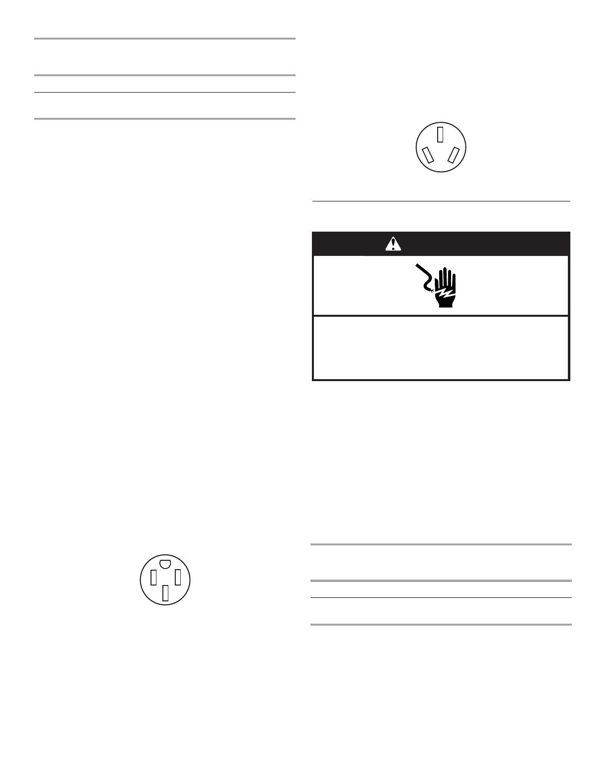
If connecting to a 3-wire system:
Local codes may permit the use of a UL listed, 3-wire,
250 volt, 40-amp range power supply cord (pigtail). This cord
contains 3 copper conductors with ring terminals or open-end
spade terminals with upturned ends, terminating in a NEMA Type
10-50P plug on the supply end. Connectors on the appliance end
must be provided at the point the power supply cord enters the
appliance. This uses a 3-wire receptacle of NEMA Type 10-50R.
Electrical Requirements - Canada Only
If codes permit and a separate ground wire is used, it is
recommended that a qualified electrical installer determine that
the ground path is adequate and wire gauge are in accordance
with local codes.
Be sure that the electrical connection and wire size are adequate
and in conformance with CSA Standard C22.1, Canadian
Electrical Code, Part 1 - latest edition, and all local codes and
ordinances.
A copy of the above code standards can be obtained from:
Canadian Standards Association
178 Rexdale Blvd.
Toronto, ON M9W 1R3 CANADA
Check with a qualified electrical installer if you are not sure
the range is properly grounded.
*The NEC calculated load is less than the total connected load
listed on the model/serial rating plate.
A time-delay fuse or circuit breaker is recommended.
Range Rating* Specified Rating of
Power Supply Cord Kit
and Circuit Protection
120/240 Volts 120/208 Volts Amps
8.8 - 16.5 KW
16.6 - 22.5 KW
7.8 - 12.5 KW
12.6 - 18.5 KW
40 or 50**
50
4-wire receptacle (14-50R)
3-wire receptacle (10-50R)
Range Rating* Specified Rating of
Power Supply Cord Kit
and Circuit Protection
120/240 Volts 120/208 Volts Amps
8.8 - 16.5 KW
16.6 - 22.5 KW
7.8 - 12.5 KW
12.6 - 18.5 KW
40 or 50
50
WARNING
Electrical Shock Hazard
Electrically ground range.
Failure to do so can result in death, fire, or
electrical shock.
7
This range is equipped with a CSA International Certified
Power Cord intended to be plugged into a standard 14-50R
wall receptacle. Be sure the wall receptacle is within reach of
range’s final location.
Do not use an extension cord.
Countertop Preparation
(for Slide-in Ranges Only)
The cooktop sides of the slide-in range fit over the cutout edge of
your countertop.
If you have a square finish (flat) countertop and the opening width
is 30" (76.2 cm), no countertop preparation is required.
Formed front-edged countertops must have molded edge
shaved flat ³⁄₈" (1.0 cm) from each front corner of opening.
Tile countertops may need trim cut back ³⁄₈" (1.0 cm) from each
front corner and/or rounded edge flattened.
If countertop opening width is greater than 30" (76.2 cm), adjust
the ³⁄₈" (1.0 cm) dimension.
Countertop must be level. Place level on countertop, first side to
side, then front to back. If countertop is not level, range will not
be level. Range must be level for satisfactory baking conditions.
INSTALLATION
INSTRUCTIONS
Unpack Range
1. Remove shipping materials, tape and film from the range.
Keep cardboard bottom under range. Remove oven racks
and parts package from inside oven.
2. To place range on its back, take 4 cardboard corners from the
carton. Stack one cardboard corner on top of another.
Repeat with the other 2 corners. Place them lengthwise on
the floor behind the range to support the range when it is laid
on its back. Using 2 or more people, firmly grasp the range
and gently lay it on its back on the cardboard corners.
Measure for Proper Height
Slide-In Ranges:
1. Measure the distance of the countertop to the floor. Measure
at all 4 locations corresponding to the 4 corners of the
underside of the range cooktop, as shown.
2. Measure from the floor to the underside of the range cooktop.
3. Your leveling height will be the difference between the
2 measurements you have just taken.
30"
(76.2 cm)
30 ¾"
(78.1 cm)
³⁄₈"
(1.0 cm)
WARNING
Excessive Weight Hazard
Use two or more people to move and install range.
Failure to do so can result in back or other injury.
Measure at locations marked A, B, C, D.
A. Distance from floor to underside of range cooktop
B. Range side frame
C. Cooktop
A
C
D
B
B
C
A
8
Freestanding Ranges:
1. Measure the distance of the countertop to the floor.
2. Then measure from the top of the range cooktop trim to the
floor.
3. Your leveling height will be the difference between the
2 measurements you have just taken.
Adjust Leveling Legs
1. If range height adjustment is necessary, use a wrench or
pliers to loosen the 4 leveling legs.
This may be done with the range on its back or with the range
supported on 2 legs after the range has been placed back to
a standing position.
NOTE: To place range back up into a standing position, put a
sheet of cardboard or hardboard in front of range. Using 2 or
more people, stand range back up onto the cardboard or
hardboard.
2. Adjust the leveling legs to the correct height. Leveling legs
can be loosened to add up to a maximum of 1" (2.5 cm). A
minimum of ³⁄₁₆" (5 mm) is needed to engage the anti-tip
bracket.
NOTE: If height adjustment is made when range is standing,
tilt the range back to adjust the front legs, then tilt forward to
adjust the rear legs.
3. When the range is at the correct height, check that there is
adequate clearance under the range for the anti-tip bracket.
Before sliding range into its final location, check that the anti-
tip bracket will slide under the range and onto the rear
leveling leg prior to anti-tip bracket installation.
Install Anti-Tip Bracket
Contact a qualified floor covering installer for the best procedure
for drilling mounting holes through your type of floor covering.
Before moving range, slide range onto shipping base, cardboard
or hardboard.
1. Remove template from the anti-tip bracket kit (found inside
the oven cavity) or from the back page of this manual.
2. Place template on the floor in cabinet opening so that the left
edge is against cabinet and top edge is against rear wall,
molding or cabinet.
3. Tape template in place.
4. If countertop is not flush with cabinet opening edge, align
template with overhang.
If cabinet opening is wider than specified in the “Location
Requirements” section, adjust template so range will be
centered in cabinet opening.
5. To mount anti-tip bracket to wood floor, drill two ¹⁄₈" (3.2 mm)
holes at the positions marked on the bracket template.
Remove template from floor.
To mount anti-tip bracket to concrete or ceramic floor, use a
³⁄₁₆" (4.8 mm) masonry drill bit to drill 2 holes at the positions
marked on the bracket template. Remove template from floor.
Tap plastic anchors into holes with a hammer.
A. Distance from the top of the range cooktop trim to the floor
A
WARNING
Tip Over Hazard
A child or adult can tip the range and be killed.
Connect anti-tip bracket to rear range foot.
Reconnect the anti-tip bracket, if the range is moved.
Failure to follow these instructions can result in death
or serious burns to children and adults.
9
6. Align anti-tip bracket holes with holes in floor. Fasten anti-tip
bracket with screws provided.
Depending on the thickness of your flooring, longer screws
may be necessary to anchor the bracket to the subfloor.
Longer screws are available from your local hardware store.
7. Move range close enough to opening to allow for electrical
connections to be made. Remove cardboard or hardboard
from under range.
8. Make electrical connections as described in the “Electrical
Connection” section.
9. Move range into its final location, making sure rear leveling
leg slides into anti-tip bracket.
10. Continue installing your range using the following installation
instructions.
Electrical Connection - U.S.A. Only
1. Disconnect power.
2. Remove the terminal block cover screws located on the back
of the range. Pull cover down and toward you to remove
cover.
3. Remove plastic tag holding three 10-32 hex nuts from the
middle post of the terminal block.
4. Add strain relief.
Style 1: Power supply cord strain relief
Remove the knockout at the bottom of the terminal box
for the 40-amp supply cord.
Power Supply Cord Direct Wire
WARNING
Electrical Shock Hazard
Disconnect power before servicing.
Use a new 40 amp power supply cord.
Plug into a grounded outlet.
Failure to follow these instructions can result in death,
fire, or electrical shock.
WARNING
Electrical Shock Hazard
Disconnect power before servicing.
Use 8 gauge copper or 6 gauge aluminum wire.
Electrically ground range.
Failure to follow these instructions can result in death,
fire, or electrical shock.
A. Hold-down screws
B. Terminal block cover
A
B
10
Assemble a UL listed strain relief in the opening.
Feed the power supply cord behind the black horizontal
cross brace and through the strain relief, allowing enough
slack to easily attach the wiring to the terminal block.
Tighten strain relief screw against the power supply cord.
Style 2: Direct wire strain relief
Remove the knockout as needed for the flexible conduit
connection.
Assemble a UL listed conduit connector in the opening.
Feed the flexible conduit behind the black horizontal
cross brace and through the strain relief, allowing enough
slack to easily attach the wiring to the terminal block.
Tighten strain relief screw against the flexible conduit.
5. Complete installation following instructions for your type of
electrical connection:
4-wire (recommended)
3-wire (if 4-wire is not available)
Electrical Connection Options
A. UL listed strain relief
A. Black horizontal cross brace
B. Power supply cord
A. Removable retaining nut
B. UL listed strain relief
A
B
A
A
B
A. Black horizontal cross brace
B. Flexible conduit
If your home has: And you will be
connecting to:
Go to Section:
4-wire receptacle
(NEMA type 14-50R)
A UL listed,
250-volt
minimum,
40-amp, range
power supply
cord
4-wire connection:
Power supply cord
4-wire direct A fused
disconnect or
circuit breaker
box
4-wire connection:
Direct wire
3-wire receptacle
(NEMA type 10-50R)
A UL listed,
250-volt
minimum,
40-amp, range
power supply
cord
3-wire connection:
Power supply cord
3-wire direct A fused
disconnect or
circuit breaker
box
3-wire connection:
Direct wire
B
A
(12.7 cm)
5"
3"
(7.6 cm)
³⁄₈"
(1.0 cm)
11
4-wire connection: Power Supply Cord
Use this method for:
New branch-circuit installations (1996 NEC)
Mobile homes
Recreational vehicles
In an area where local codes prohibit grounding through the
neutral.
1. Cut out and remove part of the metal ground strap (B).
2. Use a Phillips screwdriver to remove the ground-link screw
from the back of the range. Save the ground-link screw and
the end of the ground link under the screw.
3. Feed the power supply cord through the strain relief on the
cord/conduit plate on bottom of range. Allow enough slack to
easily attach the wiring to the terminal block.
4. Use a Phillips screwdriver to connect the green ground wire
from the power supply cord to the range with the ground-link
screw and ground-link section. The ground wire must be
attached first.
5. Use ³⁄₈" nut driver to connect the neutral (white) wire to the
center terminal block post with one of the 10–32 hex nuts.
6. Connect line 2 (red) and line 1 (black) wires to the outer
terminal block posts with 10-32 hex nuts.
7. Securely tighten hex nuts.
NOTE: For power supply cord replacement, use only a power
cord rated at 250 volts minimum, 40 amps or 50 amps that is
marked for use with nominal 1³⁄₈" (3.5 cm) diameter
connection opening, with ring terminals and marked for use
with ranges.
8. Tighten strain relief screws.
9. Replace terminal block access cover.
3-wire connection: Power Supply Cord
Use this method only if local codes permit connecting chassis
ground conductor to neutral wire of power supply cord.
1. Feed the power supply cord through the strain relief on the
cord/conduit plate on bottom of range. Allow enough slack to
easily attach the wiring to the terminal block.
A. Metal ground strap
B. Discard
C. Ground-link screw
A. Terminal block
B. Ground-link screw
C. UL listed strain relief
D. Power supply cord wires
A
B
C
A
B
D
C
A. 10–32 hex nut
B. Ground-link screw
C. Line 2 (red)
D. Green ground wire
E. Neutral (center) wire
F. Line 1 (black)
A. Terminal block
B. Ground-link screw
C. UL listed strain relief
D. Power supply cord wires - large opening
A
B
C
F
D
E
A
B
D
C
12
2. Use ³⁄₈" nut driver to connect the neutral (white) wire to the
center terminal block post with one of the 10–32 hex nuts.
3. Connect line 2 (red) and line 1 (black) wires to the outer
terminal block posts with 10-32 hex nuts.
4. Securely tighten hex nuts.
NOTE: For power supply cord replacement, use only a power
cord rated at 250 volts minimum, 40 amps or 50 amps that is
marked for use with nominal 1³⁄₈" (3.5 cm) diameter
connection opening, with ring terminals and marked for use
with ranges.
5. Tighten strain relief screws.
6. Replace terminal block access cover.
Direct Wire Installation: Copper or Aluminum Wire
This range may be connected directly to the fuse disconnect or
circuit breaker box. Depending on your electrical supply, make
the required 3-wire or 4-wire connection.
1. Strip outer covering back 3" (7.6 cm) to expose wires. Strip
the insulation back ³⁄₈" (1.0 cm) from the end of each wire.
2. Allow enough slack in the wire to easily attach the wiring
terminal block.
3. Complete electrical connection according to your type of
electrical supply (4-wire or 3-wire connection).
4-wire Connection: Direct Wire
Use this method for:
New branch-circuit installations (1996 NEC)
Mobile homes
Recreational vehicles
In an area where local codes prohibit grounding through the
neutral
1. Cut out and remove part of the metal ground strap (B).
2. Use a Phillips screwdriver to remove the ground-link screw
from the back of the range. Save the ground-link screw and
the end of the ground link under the screw.
3. Pull the wires through the strain relief on bottom of range.
Allow enough slack to easily attach wiring to the terminal
block.
4. Attach terminal lugs to line 1 (black), neutral (white), and line 2
(red) wires. Loosen (do not remove) the setscrew on the front
of the terminal lug and insert exposed wire end through
bottom of terminal lugs. Securely tighten setscrew to torque
as shown in the following Bare Wire Torque Specifications
chart.
A. 10–32 hex nut
B. Line 2 (red)
C. Ground-link screw
D. Neutral (white) wire
E. Line 1 (black)
A
B
C
D
E
3"
(7.6 cm)
³⁄₈"
(1.0 cm)
A. Metal ground strap
B. Discard
C. Ground-link screw
A. Terminal block
B. Ground-link screw
C. Cord/conduit plate
D. Bare (green) ground wire
E. Line 2 (red) wire
F. Neutral (white) wire
G. Line 1 (black) wire
A. Terminal lug
B. Setscrew
C. Line 2 (red) wire
D. Neutral (white) wire
E. Line 1 (black) wire
A
B
C
A
B
C
D
E
G
F
A
B
C
DE
13
Bare Wire Torque Specifications
Attaching terminal lugs to the terminal block - 20 lbs-in. (2.3 N-m)
5. Use a hex or Phillips screwdriver to connect the bare (green)
ground wire to the range with the ground-link screw and
ground-link section. The ground wire must be attached first
and must not contact any other terminal.
6. Use ³⁄₈" nut driver to connect the neutral (white) wire to the
center terminal block post with one of the 10–32 hex nuts.
7. Connect line 2 (red) and line 1 (black) wires to the outer
terminal block posts with 10-32 hex nuts.
8. Securely tighten hex nuts.
9. Replace terminal block access cover.
3-wire connection: Direct Wire
Use this method only if local codes permit connecting ground
conductor to neutral supply wire.
1. Pull the wires through the conduit on cord/conduit plate on
bottom of range. Allow enough slack to easily attach the
wiring to the terminal block.
2. Attach terminal lugs to line 2 (red), bare (green) ground, and
line 1 (black) wires. Loosen (do not remove) the setscrew on
the front of the terminal lug and insert exposed wire end
through bottom of terminal lugs. Securely tighten setscrew to
torque as shown in the following Bare Wire Torque
Specifications chart.
Bare Wire Torque Specifications
Attaching terminal lugs to the terminal block - 20 lbs-in. (2.3 N-m)
3. Use ³⁄₈" nut driver to connect the bare (green) ground wire to
the center terminal block post with one of the 10–32 hex nuts.
4. Connect line 2 (red) and line 1 (black) wires to the outer
terminal block posts with 10-32 hex nuts.
5. Securely tighten hex nuts.
6. Replace terminal block access cover.
Wire Awg Torque
8 gauge copper 25 lbs-in. (2.8 N-m)
6 gauge aluminum 35 lbs-in. (4.0 N-m)
A. 10–32 hex nut
B. Line 2 (red)
C. Bare (green) ground wire
D. Ground-link screw
E. Neutral (white) wire
F. Line 1 (black)
G. Terminal lug
A. Terminal block
B. Ground-link screw
C. Cord/conduit plate
D. Line 2 (red) wire
E. Bare (green) ground wire
F. Line 1 (black) wire
G. Metal ground strap
B
A
G
E
C
D
F
A
B
C
D
E
F
G
A. Terminal lug
B. Setscrew
C. Line 2 (red) wire
D. Bare (green) ground wire
E. Line 1 (black) wire
Wire Awg Torque
8 gauge copper 25 lbs-in. (2.8 N-m)
6 gauge aluminum 35 lbs-in. (4.0 N-m)
A. 10–32 hex nut
B. Line 2 (red)
C. Ground-link screw
D. Bare (green) ground wire
E. Line 1 (black)
F. Te rm i n al lu g
A
B
C
DE
B
F
A
E
D
C
14
Verify Anti-Tip Bracket Location
IMPORTANT:
On models with a warming drawer, the rear range foot must
be viewed from the front and slightly to one side of the range.
On models with a storage drawer, the drawer may be
removed to better view the rear range foot.
1. To remove storage drawer:
Pull drawer straight out to the first stop.
Lift up the back of the drawer and pull out.
2. To check that the anti-tip bracket is installed, use a flashlight
and look underneath the bottom of the range.
Look for the anti-tip bracket securely attached to floor.
Slide range back so rear range foot is under anti-tip
bracket.
Level Range
1. Place rack in oven.
2. Place level on rack and check levelness of the range, first
side to side; then front to back.
3. If range is not level, pull range forward until rear leveling leg is
removed from the anti-tip bracket.
Use pliers or wrench to adjust leveling legs up or down until
range is level. Push range back into position. Check that rear
leveling leg is engaged in anti-tip bracket.
NOTE: Range must be level for satisfactory baking
performance.
4. Replace the storage drawer:
Fit the ends of the drawer rails into the guides in the
cavity.
Slide the drawer closed.
Complete Installation
1. Check that all parts are now installed. If there is an extra part,
go back through the steps to see which step was skipped.
2. Check that you have all of your tools.
3. Dispose of/recycle all packaging materials.
4. Check that the range is level. See the “Level Range” section.
5. Use a mild solution of liquid household cleaner and warm
water to remove waxy residue caused by shipping material.
Dry thoroughly with a soft cloth. For more information, read
the “Range Care” section of the Use and Care Guide.
6. Read the “Range Use” section in the range Use and Care
Guide.
7. Plug in range or reconnect power.
8. Turn on surface burners and oven. See the Use and Care
Guide for specific instruction on range operation.
If range does not operate, check the following:
Household fuse is intact and tight; or circuit breaker has not
tripped.
Range is plugged into an outlet.
Electrical supply is connected.
See the “Troubleshooting” section in the Use and Care Guide.
When the range has been on for 5 minutes, check for heat. If
range is cold, turn off the range and contact a qualified
technician.
Moving the Range
When moving range, slide range onto cardboard or hardboard to
avoid damaging the floor covering.
WARNING
Tip Over Hazard
A child or adult can tip the range and be killed.
Connect anti-tip bracket to rear range foot.
Reconnect the anti-tip bracket, if the range is moved.
Failure to follow these instructions can result in death
or serious burns to children and adults.
15
If removing the range is necessary for cleaning or maintenance:
For power supply cord-connected ranges:
1. Using two or more people, slide range onto cardboard or
hardboard to perform cleaning or maintenance.
2. Unplug the power supply cord.
3. Perform cleaning or maintenance.
4. Plug in range.
5. Check that anti-tip bracket is installed:
Look for the anti-tip bracket securely attached to floor.
Slide range back so rear range foot is under anti-tip
bracket.
6. Check that range is level.
For direct-wired ranges:
1. Disconnect power.
2. Using two or more people, slide range onto cardboard or
hardboard to perform cleaning or maintenance.
3. Disconnect wiring (if necessary).
4. Perform cleaning or maintenance.
5. Reconnect wiring (if necessary). See “Electrical Connection -
U.S.A. Only” section.
6. Check that anti-tip bracket is installed:
Look for the anti-tip bracket securely attached to floor.
Slide range back so rear range foot is under anti-tip
bracket.
7. Check that range is level and reconnect power.
WARNING
Electrical Shock Hazard
Disconnect power before servicing.
Replace all parts and panels before operating.
Failure to do so can result in death or electrical shock.
  • Page 1 1
  • Page 2 2
  • Page 3 3
  • Page 4 4
  • Page 5 5
  • Page 6 6
  • Page 7 7
  • Page 8 8
  • Page 9 9
  • Page 10 10
  • Page 11 11
  • Page 12 12
  • Page 13 13
  • Page 14 14
  • Page 15 15
  • Page 16 16
  • Page 17 17
  • Page 18 18
  • Page 19 19
  • Page 20 20
  • Page 21 21
  • Page 22 22
  • Page 23 23
  • Page 24 24

KitchenAid KESK901SSS User manual

Category
Ovens
Type
User manual
This manual is also suitable for

Ask a question and I''ll find the answer in the document

Finding information in a document is now easier with AI

in other languages