13
Slide plastic tube snug
Against toggle switch.
18057 Harness - Wiring, Briggs (13-20 hp)
BCSR Cable - Battery (10" Red)
BCLB Cable - Battery (19 1/2"or 20" Black)
KSK Keys - For Key Switch (set of two)
BCBT Boot - Rubber, Small, Battery Cable
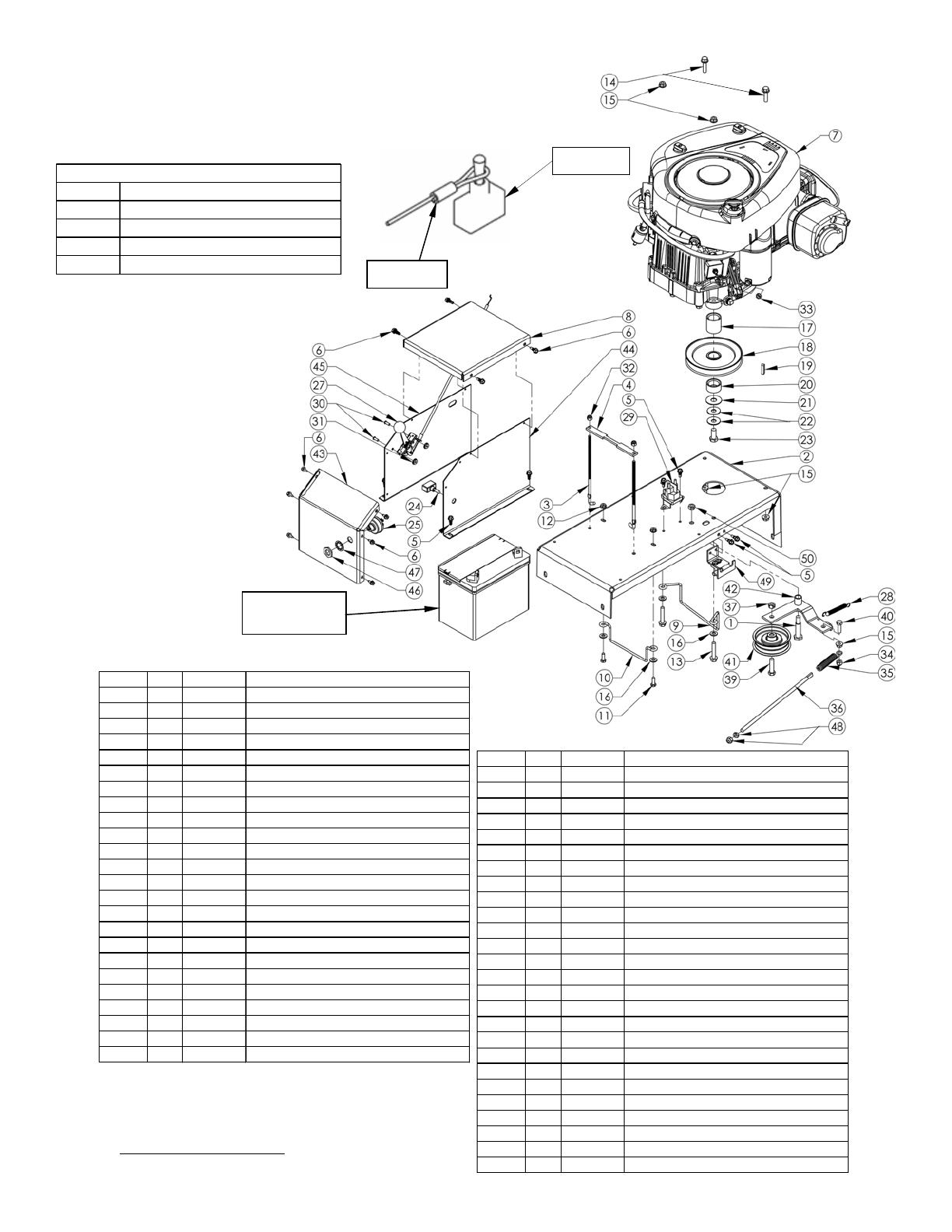
ITEM # QTY. PART NO. DESCRIPTION
1 1 NB220 Bolt - Shlder, 1/2 X 1-9/16 W3/4 Gr2 ZY
2 1 18387* Motor Base - Weldment
3 2 17760 Bolt-L
4 1 17794* Bracket - Battery Hold Down
5 8 26x229 Screw - Hex Tek 1/4 X 1/2
6 10 024206 Screw - 12 X 1/2 Hex Self Tap
7 1 N/A Engine (Reference Model Shown)
8 1 17840* Cover - Battery Top
9 1 6000 Guide - Belt
10 1 14869 Guide - Belt; T60
11 2 NB250 Bolt - 1/4-20 X 3/4 GR5
12 2 NB524 Nut - Serr Flange, 1/4-20 Grade 5
13 2 NB515 Bolt - Serr Flange,5/16-18 X1 3/4 Gr5
14 2 NB253 Bolt - Serr Flange, 5/16-18 X1 1/4 Gr5
15 5 NB170 Nut - Serr Flange 5/16-18 Case Hrd
16 4 NB275 Washer - SAE Flat 5/16
17 1 689L Spacer - Long, Engine Pulley, 1.5"
18 1 688 Pulley - Engine, 5.5"
19 1 9031 Key Stock - 1/4 X 1 Undr Size
20 1 689S Spacer - Short, Engine Pulley, .687
21 1 TR150W Washer - .531IDX1 1/2ODX.062(Ht Trtd)
22 2 699 Washer - Belleville 7/16 X 1 1/4
23 1 NB452N Bolt - 7/16-20 X 1 HCF GR5 Nylock
Switch - Toggle, Single Pole
ITEM # QTY. PART NO. DESCRIPTION
25 1 3623 Switch - Key
26 1 H9C Tether - Safety, Coiled
27 1 17898 Cable - Throttle; T60
28 1 T2SM Spring
29 1 1002004 Solenoid - 3 Pole
30 2 NB197 Screw - Phillips Truss 8-32 X 1/2
31 2 NB201 Nut - Kep 8-32
32 2 NB180 Nut - Nylock 1/4-20
33 1 NB203 Nut - Kep 1/4-20
34 3 NB181 Nut - Nyloc 5/16-18
35 1 4422 Spring - Idler Tension, Bent Leg
36 1 10636YZ Bolt - Spade, 5/16-18 X12
37 1 NB280 Nut - 2 Way Lock 3/8-16 Wax Gr A
38 1 NB272 Washer - SAE Flat 3/8
39 1 NB107 Bolt - 3/8-16 X 1 1/2 HCC GR5
40 1 NB501 Bolt - 5/16-18 X 1 HCC GR5
41 1 B527 Pulley - Idler, OD-3.25", ID-3/8"
42 1 6009* Idler - Engage Weldment
43 1 17614* Cover - Battery Top Front
44 1 17615* Cover - Battery Left
45 1 17616* Cover - Battery Right
46 1 9087 Nut - Key Switch
47 1 9088 Washer - Lock, Key Switch
48 1 NB210Z Nut - 5/16-18 HNC
49 1 -- See Saftey Switch Detail
Item # 26
Item # 24
MOTOR BASE DETAIL
U1 Battery
(Not Included)
When ordering replacement parts
*USE PAINT CODE: GT=GRAY TK=BLACK


