Page is loading ...

Info
Link
CPEC306
Closed-Path Eddy-Covariance System
• Do not connect or disconnect the EC155 gas analyzer head or the CSAT3A son-
ic anemometer head from the EC100 electronics while the EC100 is powered.
Doing so can result in unpredictable performance of the system or damage to
the instrument head.
• Grounding electrical components in the measurement system is critical. Prop-
er earth (chassis) grounding will ensure maximum electrostatic discharge
(ESD) protection and higher measurement accuracy.
• Use care when connecting and disconnecting tube ttings to avoid introduc-
ing dust or other contaminants.
• Do not overtighten the tube ttings. Consult the manual for information on
proper connection.
• The CPEC306 power source should be designed thoughtfully to ensure unin-
terrupted power. If needed, contact Campbell Scientic for assistance.
• Retain all spare caps and plugs as these are required when shipping or
storing the CPEC306 system.
IMPORTANT NOTE: This Quick Deploy Guide is meant to be a general
reference to give the installer an overview of the steps required to
make this system operational. The Owner’s Manual is the denitive
source for detailed installation instructions and information.
1
Caution!
!
CSAT3A Sonic
Anemometer Head
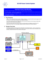
Using the CR1000KD keypad to congure settings and zero/span on a deployed system
The following tools are required to install the CPEC306 system in the eld. Addi-
tional tools may be required for a user-supplied tripod or tower.
Attach the horizontal crossarm pole to the desired height on the tripod.
3
Physical Deployment
1. Set up the tripod and crossarm pole.
Secure the tripod to the ground.
QUICK DEPLOY GUIDE
Document Part Number: 34223
Revision Date: September 2018
CM210 crossarm-
to-pole bracket
crossarm
When not using datalogger support software such as Loggernet, turn on the +12
Vdc power supply and use the CR1000KD keypad to congure the settings and
zero/span.
1. Press Enter to activate the display. Press
Enter again to display the System Control
menu.
2. On the System Control menu, select Site Var
Settings to customize site specic variables.
3. Enter site-specic variables. Press Esc when
complete to return to the main menu.
4. On the System Control menu, select Const
Table to modify sensor information.
5. Add and remove sensors by selecting -1 for
true and 0 for false. Once the changes are
completed, select Apply and Restart at
the bottom of the screen. Select Yes to save
the changes. The device will then restart.
Site Var Settings:
Meas height :2.00000
Pck Surf typ : GRASS
Canopy hght :0.50000
d, 0 = auto :0.00000
Z0,0 = auto :0:00000
GPS height :2.00000
Bulk density :1300.00
NMBR_HFP : 4
HFP_SNSTVT_1 : 62.0000
HFP_SNSTVT_2 : 62.0000
HFP_SNSTVT_3 : 62.0000
HFP_SNSTVT_4 : 62.0000
CAL_INTV : 1440
Apply and Restart
2
Required Gear
1. 9/16-in, open-end wrench
2. 1/2-in, open-end wrench
3. 11/16-in, open-end wrench
4. Adjustable wrench
5. Small, at-tip screwdriver
6. Large, at-tip screwdriver
7. Sledgehammer (to drive ground-
ing rod into the ground)
8. 3/16-in hex-key wrench
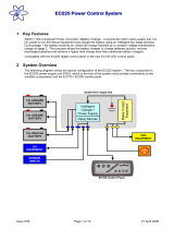
Sample Intake Assembly
with EC155 Gas Analyzer
EC100 Electronics
CPEC306 Enclosure
CPEC306 System Diagram

4. Connect the EC155 and CSAT3A to the electronics.
5. Ground the tripod and the enclosures.
6. Connect the system plumbing.
7. Wiring.
Connect the SDM from the main enclosure and EC100 power cables to the EC100
electronics.
Draw the EC100 power cable and EC100 SDM cable through the feedthrough at the
bottom of the CPEC306 enclosure and connect them to the DINrail.
8. Datalogger
Insert a MicroSD card into the datalogger and connect power.
Turn on the +12 Vdc power supply and use either LoggerNet, PC200W, or PC400 on a
laptop to congure settings and zero/span. If using the CR1000KD keypad, use the instruc-
tions on the front page of this quick deploy guide.
1. Connect to the datalogger
2. Connect and select the Const_Table within the EasyFlux
TM
DL program.
3. Conrm all the sensors used at the site
are set to -1. To change a value in this
table, right-click on the current value
and select View/Modify from the
pop-up menu. Press Apply once the
new value has been entered.
Once all of the sensors and constant
settings are correct, scroll to the
bottom and set ApplyAndRestart
to true.
4. Review the Public table and conrm that site specic variables are set appropriately.
Note: Setting these variables does not require an ApplyAndRestart.
2. Setup and mount sensors
Mount the EC155 bypass tube.
Connect the CM250 mount to the crossarm and then connect the sensors mounted
on the Mounting Platform, as shown. Use the bubble level on the CSAT3A to level the
platform.
3. Mount the enclosures.
Mount the enclosures on the legs of the tripod as shown.
EC155/CSAT3A
mounting platform
CM250 leveling
mount
CSAT3A Sonic
Anemometer head
Sample Intake Assembly
with EC155 Gas Analyzer
crossarm
EC155 analyzer cable
CSAT3A cable
EC155 sample cell cable
Ground rod
Ground lug
CPEC306
enclosure
Power cable to
+12Vdc power
supply (Do not
apply power until
the CPEC306 is fully
wired.)
Power cable
to EC100
Ground cable to
+12Vdc power
supply (o)
Ground cable
to EC100
SDM black and
clear ground wires
SDM cable to
EC100
Mounting clip
EC155 bypass tube
EC100 SDM cable
EC100 Power Cable
This wire may be brown or red
4
Conguring with LoggerNet/PC200W or PC400
EC155 w/ CSAT3A
CPEC306 Enclosure
EC100 electronics
Analyzer Tubing
/