GOVERNOR
SYSTEM
COMPONENTS
and
OPERATION
DESCRIPTION
The Electronic Governor consists of three components,
the
CONTROLLER,
a
pc
board installed
in
the
control
panel.
A
MAGNETIC
PICK-UP
(MPU)
installed
in
the
bellhousing over
the
engine
flywheel
and
the
linear
ACTUATOR
mounted
on
the
engine
and
attached
by
linkage
to
the
injection
pump
throttle control. ·
SYSTEM
OPERATION
On
start
up
system
DC
voltage
is
supplied
to
the
controller
to
use
for actuator
operation.
When
the starter
is
energized
and
the
engine cranks,
the
magnetic
pick-up
(MPU)
that
is
positioned over
the
engines
flywheel
ring gear
sends
a
low
AC
signal
to
the
controller
(1.5
-
2.5
AC
volts).
The controller interprets
this
as
engine cranking speed
and
sends
a
DC
voltage
to
the
actuator
to
operate
the
carburetor's
throttle ann. The position of the throttle
by
the
actuator
has
been previously determined
by
the
speed adjustment on
the
speed
controller.
The engine carries
up
to
a set speed
determined
by
the
AC
voltage sent
by
the
MPU.
The
speed
controller maintains
this
signal
no
load
to
full
load
by
varying
the
DC
voltage
to
the
actuator providing
more
or
less
throttle depending
on
the
generator
load.
Gain
Adjustment
The
gain
can
be
adjusted
using
a small
screwdriver.
Adjustment should
be
between
30%
and
40%
as
is
required
to
dampen speed oscillation under
load.
An adjustment of
more
than
40%
can
cause
the
unit
to
race (speed
up)
when
the
load
is
removed
or
go
into a hunting
mode.
Speed
Controller
50
\ I I
'CS);
- -
,
....
I \
0 '\00
GAIN
ADJUSTMENT
The speed controller has a
green
LED
indicating power to
the
controller, a
plus
and
minus
speed adjustment (buttons)
and
a
gain
adjustment.
The green
LED
blinks
when
the
power
is
turned
on
and
after
it
receives a signal
from
the
magnetic pick-up, it blinks at a faster
rate.
GAIN
2
ELECTRONIC
SPEED
~
CONTROUER
MAGNETIC
PICK·UP
[MPUJ
INSTALLATION
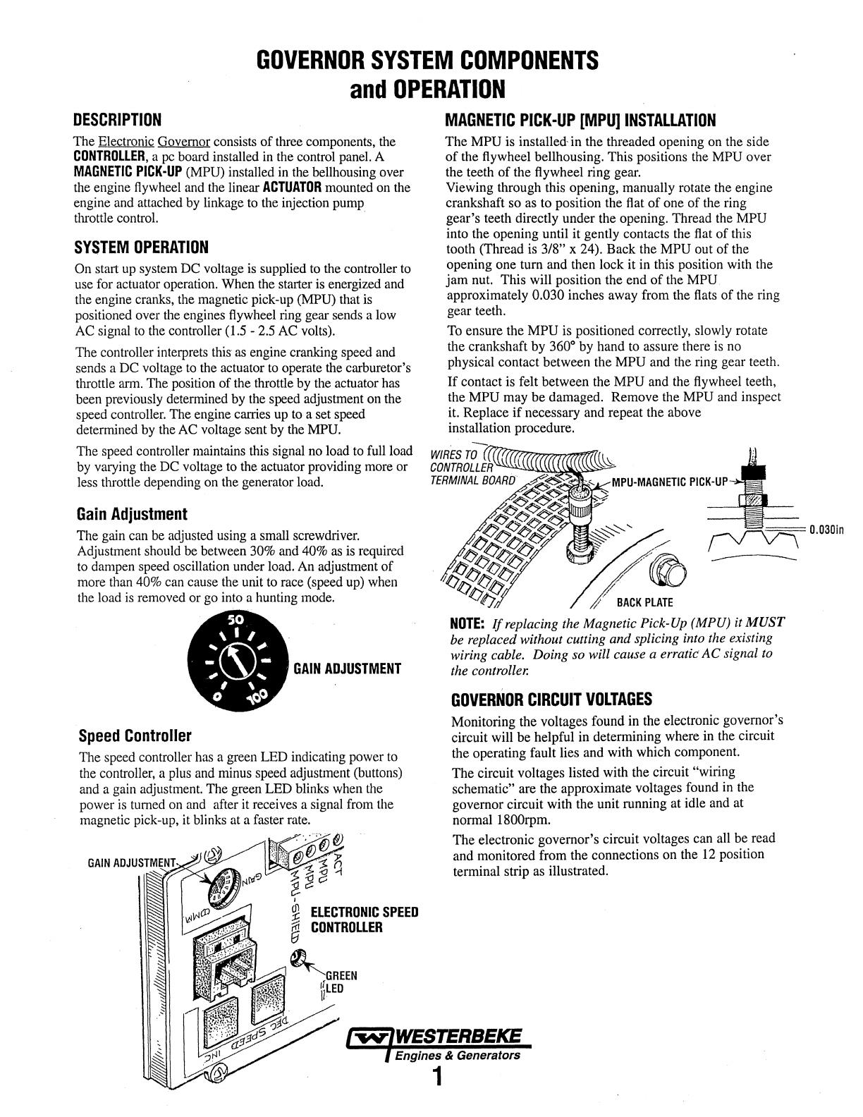
The
MPU
is installed·
in
the threaded opening
on
the side
of the flywheel bellhousing. This positions
the
MPU
over
the teeth of the flywheel ring
gear.
Viewing through this opening, manually rotate the engine
crankshaft so
as
to position
the
flat
of
one
of
the
ring
gear's teeth directly under the opening. Thread
the
MPU
into the opening until it gently contacts
the
flat
of this
tooth (Thread is
3/8" x 24). Back the MPU out of the
opening one tum and then lock it
in
this position with
the
jam
nut.
This will position the end of the
MPU
approximately 0.030 inches
away
from the
flats
of
the
ring
gear teeth.
To
ensure the MPU
is
positioned correctly, slowly rotate
the crankshaft
by
360°
by
hand
to
assure there
is
no
physical contact between the
MPU
and the ring gear teeth.
If contact
is
felt between the MPU and
the
flywheel teeth,
the
MPU
may
be damaged. Remove the
MPU
and
inspect
it. Replace
if
necessary
and
repeat the above
installation procedure.
/
//~
----
,{/
/
BACK
PLATE
NOTE:
If
replacing the Magnetic Pick-Up (MPU) it
MUST
be
replaced without cutting and splicing into the existing
wiring cable. Doing so will cause a erratic'
AC
signal to
the controller.
GOVERNOR
CIRCUIT
VOLTAGES
Monitoring the voltages found in
the
electronic governor's
circuit will be helpful in determining where
in
the
circuit
the operating fault lies and with which component.
The circuit voltages listed with
the
circuit "wiring
schematic"
are the approximate voltages found
in
the
governor circuit with
the
unit running at idle
and
at
normal
1800rpm.
The electronic governor's circuit voltages can
all
be
read
and monitored from the connections on the
12
position
terminal strip
as
illustrated.
Engines & Generators
1


