
Acer Altos R510 Series
User’s Guide

Changes may be made periodically to the information in this publication without obligation
to notify any person of such revision or changes. Such changes will be incorporated in new
editions of this manual or supplementary documents and publications. This company makes
no representations or warranties, either expressed or implied, with respect to the contents
herein and specifically disclaims the implied warranties of merchantability or fitness for a
particular purpose.
Record the model number, serial number, purchase date, and place of purchase information in
the space provided below. The serial number and model number are recorded on the label
affixed to your computer. All correspondence concerning your unit should include the serial
number, model number, and purchase information.
No part of this publication may be reproduced, stored in a retrieval system, or transmitted, in
any form or by any means, electronic, mechanical, photocopy, recording, or otherwise,
without the prior written permission of Acer Incorporated.
Model Number : _________________________________
Serial Number: ___________________________________
Purchase Date: ___________________________________
Place of Purchase: ________________________________
Copyright © 2004 Acer Incorporated
All Rights Reserved.
Acer Altos R510
Series
User’s Guide
1st Issue: December 2004
Acer and the Acer logo are registered trademarks of Acer Inc. Other company’s product
names or trademarks are used herein for identification purposes only and belong to their
respective companies.

iii
Notices
FCC notice
Class A devices do not have an FCC logo or FCC IDE on the label. Class
B devices have an FCC logo or FCC IDE on the label. Once the class of
the device is determined, refer to the following corresponding
statement.
Class A equipment
This device has been tested and found to comply with the limits for a
Class A digital device pursuant to Part 15 of the FCC Rules. These limits
are designed to provide reasonable protection against harmful
interference when the equipment is operated in a commercial
environment. This device generates, uses, and can radiate radio
frequency energy, and if not installed and used in accordance with the
instructions, may cause harmful interference to radio communications.
Operation of this device in a residential area is likely to cause harmful
interference in which case the user will be required to correct the
interference at his own expense.
However, there is no guarantee that interference will not occur in a
particular installation. If this device does cause harmful interference to
radio or television reception, which can be determined by turning the
device off and on, the user is encouraged to try to correct the
interference by one or more of the following measures:
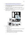
• Reorient or relocate the receiving antenna
• Increase the separation between the device and receiver
• Connect the device into an outlet on a circuit different from that
to which the receiver is connected
• Consult the dealer or an experienced radio/television technician
for help
Shielded cables
All connections to other computing devices must be made using
shielded cables to maintain compliance with FCC regulations.

iv
Peripheral devices
Only peripherals (input/output devices, terminals, printers, etc.)
certified to comply with the Class A or Class B limits may be attached to
this equipment. Operation with noncertified peripherals is likely to
result in interference to radio and TV reception.
Caution: Changes or modifications not expressly approved by
the manufacturer could void the user’s authority, which is granted
by the Federal Communications Commission, to operate this
server.
Use conditions
This part complies with Part 15 of the FCC Rules. Operation is subject to
the following two conditions: (1) this device may not cause harmful
interference, and (2) this device must accept any interference received,
including interference that may cause undesired operation.
Canadian users
This Class A/Class B digital apparatus meets all requirements of the
Canadian Interference-Causing Equipment Regulations.
Laser compliance statement
The CD-ROM drive in this server is a laser product. The CD-ROM drive’s
classification label (shown below) is located on the drive.
CLASS 1 LASER PRODUCT
CAUTION: INVISIBLE LASER RADIATION WHEN OPEN. AVOID
EXPOSURE TO BEAM.

v
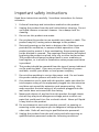
Important safety instructions
Read these instructions carefully. Save these instructions for future
reference.
1 Follow all warnings and instructions marked on the product.
2 Unplug this product from the wall outlet before cleaning. Do not
use liquid cleaners or aerosol cleaners. Use a damp cloth for
cleaning.
3 Do not use this product near water.
4 Do not place this product on an unstable cart, stand, or table. The
product may fall, causing serious damage to the product.
5 Slots and openings on the back or bottom side of the chassis are
provided for ventilation; to ensure reliable operation of the
product and to protect it from overheating, these openings must
not be blocked or covered. The openings should never be blocked
by placing the product on a bed, sofa, rug, or other similar surface.
This product should never be placed near or over a radiator or
heat register, or in a built-in installation unless proper ventilation
is provided.
6 This product should be operated from the type of power indicated
on the marking label. If you are not sure of the type of power
available, consult your dealer or local power company.
7 Do not allow anything to rest on the power cord. Do not locate
this product where persons will walk on the cord.
8 If an extension cord is used with this product, make sure that the
total ampere rating of the equipment plugged into the extension
cord does not exceed the extension cord ampere rating. Also,
make sure that the total rating of all products plugged into the
wall outlet does not exceed the fuse rating.
9 Never push objects of any kind into this product through chassis
slots as they may touch dangerous voltage points or short out
parts that could result in a fire or electric shock. Never spill liquid
of any kind on the product.
10 Do not attempt to service this product yourself, as opening or
removing covers may expose you to dangerous voltage points or
other risks. Refer all servicing to qualified service personnel.
11 Unplug this product from the wall outlet and refer servicing to
qualified service personnel under the following conditions:

vi
a When the power cord or plug is damaged or frayed
b If liquid has been spilled into the product
c If the product has been exposed to rain or water
d If the product does not operate normally when the operating
instructions are followed. Adjust only those controls that are
covered by the operating instructions since improper
adjustment of other controls may result in damage and will
often require extensive work by a qualified technician to
restore the product to normal condition.
e If the product has been dropped or the cabinet has been
damaged
f If the product exhibits a distinct change in performance,
indicating a need for service.
12 Replace the battery with the same type as the product's battery we
recommend. Use of another battery may present a risk of fire or
explosion. Refer battery replacement to a qualified service
technician.
13 Warning! Batteries may explode if not handled properly. Do not
disassemble or dispose of them in fire. Keep them away from
children and dispose of used batteries promptly.
14 Use only the proper type of power supply cord set (provided in
your accessories box) for this unit. It should be a detachable type:
UL listed/CSA certified, type SPT-2, rated 7A 125V minimum, VDE
approved or its equivalent. Maximum length is 15 feet (4.6
meters).

Notices iii
FCC notice iii
Class A equipment iii
Shielded cables iii
Peripheral devices iv
Use conditions iv
Canadian users iv
Laser compliance statement iv
Important safety instructions v
1 System information 1
Product briefing 3
Processor 3
Memory subsystem 3
Storage 4
Graphics interface 4
Networking 4
I/O ports 4
Caring features 5
Product specification summary 6
2 System tour 7
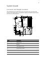
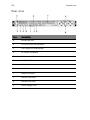
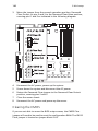
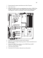
System board 9
Connector and Header Locations 9
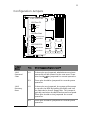
Configuration Jumpers 11
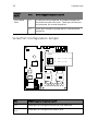
Serial Port Configuration Jumper 12
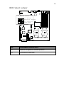
BIOS Select Jumper 13
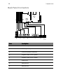
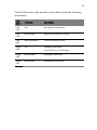
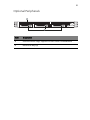
Back Panel Connectors 14
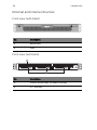
External and internal structure 16
Front view (with bezel) 16
Front view (w/o bezel) 16
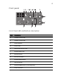
Front panel 17
Front Panel LED and Buttons description 17
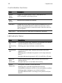
Control Button Functions 18
LED Indicator Status 18
Rear view 20
Optional Peripherals 21
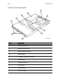
Internal components 22
3 Getting Started 23
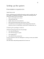
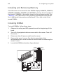
Setting up the system 25
Preinstallation requirements 25
Contents

Selecting a site 25
Checking the package contents 25
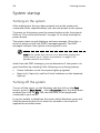
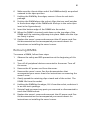
System startup 26
Turning on the system 26
Turning off the system 26
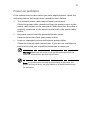
Power-on problems 27
4 Configuring the system 29
Upgrading the system 31
Installation precautions 31
ESD precautions 31
Preinstallation instructions 31
Post-installation instructions 32
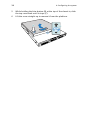
Opening the server 33
Before opening the server 33
Removing the Chassis Cover 33
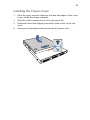
Installing the Chassis Cover 35
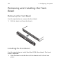
Removing and Installing the Front Bezel 36
Removing the Front Bezel 36
Installing the Front Bezel 36
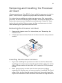
Removing and Installing the Processor Air Duct 37
Removing the Processor Air Duct 37
Installing the Processor Air Duct 37
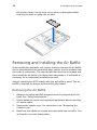
Removing and Installing the Air Baffle 38
Removing the Air Baffle 38
Installing the Air Baffle 40
Installing and Removing a Hard Disk Drive 41
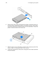
Installing a Fixed SATA Hard Disk Drive 41
Removing a Fixed SATA Hard Disk Drive 46
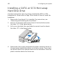
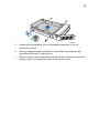
Installing a SATA or SCSI Hot-swap Hard Disk Drive 48
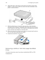
Removing a SATA or SCSI Hot-swap Hard Disk Drive 50
Installing or Removing a Floppy Drive 52
Installing a Floppy Drive into Slimline Bay (Backplane Installed)52
Removing a Floppy Drive from the Slimline Bay (Backplane In-
stalled) 55
Installing a Floppy Drive into Slimline Bay (No Backplane Installed)
55
Removing a Floppy Drive from the Slimline Bay (No Backplane In-
stalled) 60
Installing a Floppy Drive into the Converted Hard Drive Bay (Back-
plane Installed) 61
Removing a Floppy Drive from the Converted Hard Drive Bay64
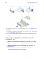
Installing or Removing a DVD/CD-RW or CD-ROM Drive 66

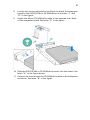
Installing a DVD/CD-RW or CD-ROM Drive into Slimline Bay (Back-
plane Installed) 66
Removing a DVD/CD-RW or CD-ROM Drive from the Slimline Bay
(Backplane Installed) 68
Installing DVD/CD-RW or CD-ROM Drive into Slimline Bay (No
Backplane Installed) 69
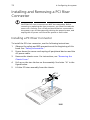
Installing and Removing a PCI Riser Connector 72
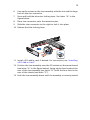
Installing a PCI Riser Connector 72
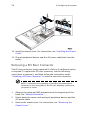
Removing a PCI Riser Connector 74
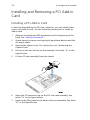
Installing and Removing a PCI Add-in Card 76
Installing a PCI Add-in Card 76
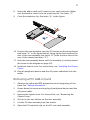
Removing a PCI Add-in Card 77
Installing and Removing the SATA or SCSI Backplane (Optional)79
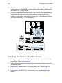
Removing the SATA or SCSI Backplane 79
Installing the SCSI or SATA Backplane 80
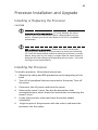
Processor Installation and Upgrade 83
Installing or Replacing the Processor 83
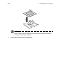
Installing the Processor 83
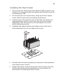
Installing the Heat Sink(s) 85
Removing a Processor 86
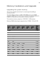
Memory Installations and Upgrade 87
Upgrading the system memory 87
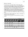
Memory Sparing 89
Installing and Removing Memory 90
Installing DIMMs 90
Removing DIMMs 91
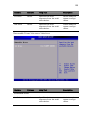
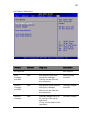
5 BIOS setup 93
Using the BIOS Setup Utility 95
Entering BIOS 95
If You Cannot Access Setup 95
Setup Menus 95
BIOS Setup Utility 96
BIOS Setup Keyboard Command Bar Options 97
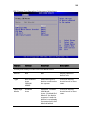
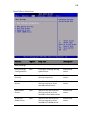
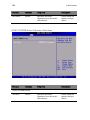
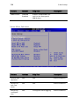
Main 99
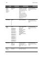
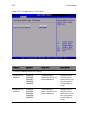
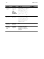
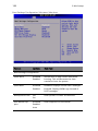
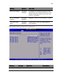
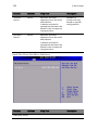
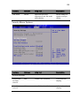
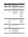
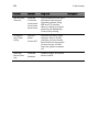
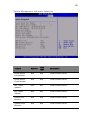
Advanced 101
Upgrading the BIOS 138
Preparing for the Upgrade 138
Recording the Current BIOS Settings 138
Obtaining the Upgrade 139
Upgrading the BIOS 139
Clearing the Password 139
Clearing the CMOS 140

6 Troubleshooting 143
Resetting the System 145
Problems following Initial System Installation 145
First Steps Checklist 145
Hardware Diagnostic Testing 146
Verifying Proper Operation of Key System Lights147
Confirming Loading of the Operating System 147
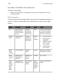
Specific Problems and Corrective Actions 147
Power Light Does Not Light 148
No Characters Appear on Screen 148
Characters Are Distorted or Incorrect 149
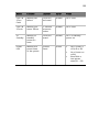
System Cooling Fans Do Not Rotate Properly 150
Diskette Drive Activity Light Does Not Light 150
CD-ROM Drive or DVD/CD-RW Drive Activity Light Does Not
Light 150
Cannot Connect to a Server 151
Problems with Network 151
System Boots when Installing PCI Card 152
Problems with Newly Installed Application Software152
Problems with Application Software that Ran Correctly Earli-
er 152
Devices are not Recognized under Device Manager (Win-
dows* Operating System) 153
Hard Drive(s) are not recognized 153
Bootable CD-ROM Is Not Detected 154
155
Appendix A: Management software installation157
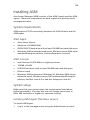
Installing ASM 159
System requirements 159
ASM Agent 159
ASM Console 159
System setup 159
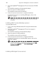
Installing ASM Agent (Windows version) 159
Installing ASM Console (Windows version) 160
Installing ASM Agent (Linux version) 160
Appendix B: Tool-less rail kit installation 163
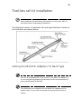
Tool-less rail kit installation 165
Setting the Multi-Pin Adapters for Rack Type 165
Installing the Slide Rails into the Rack 166
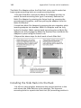
Installing the Component into the Slide Rails 168
Cable Management ARM installation 169

Required Installation Position of the CMA 170
Installing the CMA on the Slide Rails 171
Placing and Securing Cabling Within the CMA 172
General Safety Information 173
Appendix C: Sensor Table 175
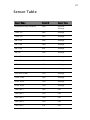
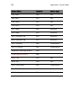
Sensor Table 177
Appendix D: SATA RAID Configuration 179
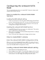
Configuring the onboard SATA RAID 181
How to enable the onboard SATA RAID function 181
Loading the BIOS default setting 181
Enabling the onboard SATA RAID function 181
How to create RAID 1 volume 181
Enter the onboard SATA RAID Configuration Utility181
Loading onboard SATA RAID default setting 181
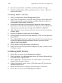
Creating RAID 1 volume 182
Initialising RAID Volume 182
Saving and Exiting the Embedded RAID Configuration Utility
183
Index 185


1 System
information

The Acer Altos R510 is a rack optimised dual
processor system loaded with features. The
system uses next generation technology to
offer excellent performance for cost sensitive
applications.

3
Product briefing
This section provides basic information concerning the configuration
of your Altos R510 system.
Processor
• Single or dual Intel
®
Xeon
TM
processors with 800 MHz FSB
• CPU Hyper-Threading
TM
Technology support
• Supports Extended memory 64bit technology (EM64T)
Memory subsystem
• Six (184 - pin) DIMM slots
• DDR-2 400 MHz registered memory modules supported
• Maximum upgrade - 12 GB
• 2-way memory interleaving supported
• SDDC (Single Device Data Correction) for memory error detection
and correction of any number of bit failures in a single x4 memory
device
• Memory sparing technology
• When memory sparing is enabled, the spare DIMM will not be
detected by OS
• The sparing DIMM will be reserved for standby purposes and
cannot be accessed by the system
1
• Please refer to page116 "Memory Configuration Sub-menu
Selections" for more information about configuring the memory
sparing in the BIOS Setup utility
1
For example, if six 1GB DIMMs are installed (6 GB memory) only
4GB of memory (in DIMM 1B, 1A, 2B, 2A) can be accessed by the
system. Memory in DIMM 3B and DIMM 3A would be reserved as
spare DIMMs
Caution! When using multiple memory modules it is
recommended that you AVOID using modules from different
manufacturers or that run at different speeds from each other.

1 System information
4
Warning! Functionality issues may be encountered if mixed
memory types are installed on the same server board. DIMM
modules of identical type, banking and stacking technology, and
vendor should be installed in the Altos R510.
Storage
• Slim-type IDE CD-ROM/DVD-ROM drive
• Slim-type 3.5 inch Floppy disk drive (optional)
• Support for three (max) SCSI hard disk drives 146 * 3 = 438GB or
three SATA hard disk drives 200 * 3 = 600GB
Warning: If FDD and CD-ROM are installed, R510 would support 2
hard disk drives only.
Graphics interface
• On-board ATI Rage XL video controller with 8MB SDRAM
Networking
• Two Integrated Gigabit Ethernet connections
• Intel 82541PI Gigabit Ethernet LAN controller
• Marvell 88E8050 Gigabit Ethernet LAN Controller
I/O ports
•Front
• One USB 2.0 port
• One SVGA video port
•Rear
• One USB 2.0 port
• Two PS/2 ports (keyboard/mouse)
• Two LAN ports (RJ-45)
• One SVGA video port

5
Serial ATA ports
• Two SATA ports
Service ID
• Front service ID button
• Front and rear service ID LED
Operating Systems supported
• Microsoft® Windows® Server 2003
• Red Hat Enterprise Linux 4.0
• Novell NetWare 6.5
• SCO Unixware 7.1.4
• SCO OpenServer 5.0.7
RAID (Optional)
• Embedded SATA Software RAID 0,1 supported
Caring features
Part of Acer’s mission, as a company that cares about its end users, is to
provide features that make operation, maintenance, and upgrading
your system simpler and faster. The Altos R510 is no exception to this
rule. The following features and options are provided.
• Cost efficient operation in a value oriented package
• Tool-less design
• Front accessible USB and VGA ports
•Acer EasyBUILD
TM
for efficient system setup and installation
• Acer Server Manager (ASM) suite of comprehensive management
tools
• Flexibility for future expansion

1 System information
6
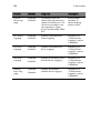
Product specification summary
Highlighted below are the system’s key features:
• Single or dual Intel
®
Xeon
TM
processor supporting Hyper-Threading
Technology
• 800 MHz FSB supports processor speeds from 3.6 GHz and above
•Intel
®
E7320 chipset consisting of:
•Intel
®
E7320 Memory Controller Hub (MCH)
•Intel
®
6300ESB I/O Controller Hub (ICH)
• Supports two PCI riser cards
• Low Profile: One 66/66MHz/3.3V PCI-X slot
• One full height riser slot supporting one of two riser card
options:
• Option 1: One 64-bit/66MHz/3.3V PCI-X slot
• Option 2: One (x4) PCI-Express slot
• Six DIMM sockets supporting DDR-2 400 registered ECC modules
for a maximum memory capacity of 12 GB
• Media storage
• Optional slim-type 3.5 inch 1.44 MB floppy drive or Optical drive
• Additional media storage capacity
• Support for three 3.5 Inch SATA, or SCSI hard disk drives
• External ports
• Power supply unit (PSU)
• One 450W power supply
• Chassis Intrusion
• Chassis intrusion switch
• Lock attach point for chassis cover
• Up to five system fans
• Four dual rotor plus one single rotor system fans
• Tool less fan replacement
•LEDs
• Standard Control Panel: NIC1 Activity, NIC2 Activity & Power /
Sleep
• System Status LEDs can be viewed with bezel closed
•Service ID
• PS/2 keyboard and mouse ports • Two LAN (RJ-45) ports
• Two USB ports (1 front, 1 rear) • 2 SVGA video ports (1
front, 1 rear

2 System tour

This chapter provides locations of various
components and ports and instructions on
how to set up the system.
Page is loading ...
Page is loading ...
Page is loading ...
Page is loading ...
Page is loading ...
Page is loading ...
Page is loading ...
Page is loading ...
Page is loading ...
Page is loading ...
Page is loading ...
Page is loading ...
Page is loading ...
Page is loading ...
Page is loading ...
Page is loading ...
Page is loading ...
Page is loading ...
Page is loading ...
Page is loading ...
Page is loading ...
Page is loading ...
Page is loading ...
Page is loading ...
Page is loading ...
Page is loading ...
Page is loading ...
Page is loading ...
Page is loading ...
Page is loading ...
Page is loading ...
Page is loading ...
Page is loading ...
Page is loading ...
Page is loading ...
Page is loading ...
Page is loading ...
Page is loading ...
Page is loading ...
Page is loading ...
Page is loading ...
Page is loading ...
Page is loading ...
Page is loading ...
Page is loading ...
Page is loading ...
Page is loading ...
Page is loading ...
Page is loading ...
Page is loading ...
Page is loading ...
Page is loading ...
Page is loading ...
Page is loading ...
Page is loading ...
Page is loading ...
Page is loading ...
Page is loading ...
Page is loading ...
Page is loading ...
Page is loading ...
Page is loading ...
Page is loading ...
Page is loading ...
Page is loading ...
Page is loading ...
Page is loading ...
Page is loading ...
Page is loading ...
Page is loading ...
Page is loading ...
Page is loading ...
Page is loading ...
Page is loading ...
Page is loading ...
Page is loading ...
Page is loading ...
Page is loading ...
Page is loading ...
Page is loading ...
Page is loading ...
Page is loading ...
Page is loading ...
Page is loading ...
Page is loading ...
Page is loading ...
Page is loading ...
Page is loading ...
Page is loading ...
Page is loading ...
Page is loading ...
Page is loading ...
Page is loading ...
Page is loading ...
Page is loading ...
Page is loading ...
Page is loading ...
Page is loading ...
Page is loading ...
Page is loading ...
Page is loading ...
Page is loading ...
Page is loading ...
Page is loading ...
Page is loading ...
Page is loading ...
Page is loading ...
Page is loading ...
Page is loading ...
Page is loading ...
Page is loading ...
Page is loading ...
Page is loading ...
Page is loading ...
Page is loading ...
Page is loading ...
Page is loading ...
Page is loading ...
Page is loading ...
Page is loading ...
Page is loading ...
Page is loading ...
Page is loading ...
Page is loading ...
Page is loading ...
Page is loading ...
Page is loading ...
Page is loading ...
Page is loading ...
Page is loading ...
Page is loading ...
Page is loading ...
Page is loading ...
Page is loading ...
Page is loading ...
Page is loading ...
Page is loading ...
Page is loading ...
Page is loading ...
Page is loading ...
Page is loading ...
Page is loading ...
Page is loading ...
Page is loading ...
Page is loading ...
Page is loading ...
Page is loading ...
Page is loading ...
Page is loading ...
Page is loading ...
Page is loading ...
Page is loading ...
Page is loading ...
Page is loading ...
Page is loading ...
Page is loading ...
Page is loading ...
Page is loading ...
Page is loading ...
Page is loading ...
Page is loading ...
Page is loading ...
Page is loading ...
Page is loading ...
Page is loading ...
Page is loading ...
Page is loading ...
Page is loading ...
Page is loading ...
Page is loading ...
Page is loading ...
Page is loading ...
Page is loading ...
Page is loading ...
Page is loading ...
Page is loading ...
Page is loading ...
Page is loading ...
-
 1
1
-
 2
2
-
 3
3
-
 4
4
-
 5
5
-
 6
6
-
 7
7
-
 8
8
-
 9
9
-
 10
10
-
 11
11
-
 12
12
-
 13
13
-
 14
14
-
 15
15
-
 16
16
-
 17
17
-
 18
18
-
 19
19
-
 20
20
-
 21
21
-
 22
22
-
 23
23
-
 24
24
-
 25
25
-
 26
26
-
 27
27
-
 28
28
-
 29
29
-
 30
30
-
 31
31
-
 32
32
-
 33
33
-
 34
34
-
 35
35
-
 36
36
-
 37
37
-
 38
38
-
 39
39
-
 40
40
-
 41
41
-
 42
42
-
 43
43
-
 44
44
-
 45
45
-
 46
46
-
 47
47
-
 48
48
-
 49
49
-
 50
50
-
 51
51
-
 52
52
-
 53
53
-
 54
54
-
 55
55
-
 56
56
-
 57
57
-
 58
58
-
 59
59
-
 60
60
-
 61
61
-
 62
62
-
 63
63
-
 64
64
-
 65
65
-
 66
66
-
 67
67
-
 68
68
-
 69
69
-
 70
70
-
 71
71
-
 72
72
-
 73
73
-
 74
74
-
 75
75
-
 76
76
-
 77
77
-
 78
78
-
 79
79
-
 80
80
-
 81
81
-
 82
82
-
 83
83
-
 84
84
-
 85
85
-
 86
86
-
 87
87
-
 88
88
-
 89
89
-
 90
90
-
 91
91
-
 92
92
-
 93
93
-
 94
94
-
 95
95
-
 96
96
-
 97
97
-
 98
98
-
 99
99
-
 100
100
-
 101
101
-
 102
102
-
 103
103
-
 104
104
-
 105
105
-
 106
106
-
 107
107
-
 108
108
-
 109
109
-
 110
110
-
 111
111
-
 112
112
-
 113
113
-
 114
114
-
 115
115
-
 116
116
-
 117
117
-
 118
118
-
 119
119
-
 120
120
-
 121
121
-
 122
122
-
 123
123
-
 124
124
-
 125
125
-
 126
126
-
 127
127
-
 128
128
-
 129
129
-
 130
130
-
 131
131
-
 132
132
-
 133
133
-
 134
134
-
 135
135
-
 136
136
-
 137
137
-
 138
138
-
 139
139
-
 140
140
-
 141
141
-
 142
142
-
 143
143
-
 144
144
-
 145
145
-
 146
146
-
 147
147
-
 148
148
-
 149
149
-
 150
150
-
 151
151
-
 152
152
-
 153
153
-
 154
154
-
 155
155
-
 156
156
-
 157
157
-
 158
158
-
 159
159
-
 160
160
-
 161
161
-
 162
162
-
 163
163
-
 164
164
-
 165
165
-
 166
166
-
 167
167
-
 168
168
-
 169
169
-
 170
170
-
 171
171
-
 172
172
-
 173
173
-
 174
174
-
 175
175
-
 176
176
-
 177
177
-
 178
178
-
 179
179
-
 180
180
-
 181
181
-
 182
182
-
 183
183
-
 184
184
-
 185
185
-
 186
186
-
 187
187
-
 188
188
-
 189
189
-
 190
190
-
 191
191
-
 192
192
-
 193
193
-
 194
194
-
 195
195
-
 196
196
-
 197
197
-
 198
198


Ask a question and I''ll find the answer in the document
Finding information in a document is now easier with AI
Related papers
Other documents
-
Luxor MB4836WW Installation guide
-
NEC Express5800/120Rf-2 User guide
-
-
Dell PowerEdge 2850 User manual
-
Sharkoon 4044951005208 Datasheet
-
 StarTech.com OPT2IDE Datasheet
-
Intel SR9000MK4U User manual
-
Gateway 7250R User manual
-
 StarTech.com SLSATAADAP Datasheet
-

