Page is loading ...

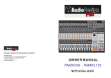
INPUT 4INPUT 3INPUT 2INPUT 1
PAD
26dB
A
B
PAD
26dB
A
B
PAD
26dB
A
B
PAD
26dB
A
B
-16
-60
+10
-34
-16
-60
+10
-34
-16
-60
-16 -60
TRIMTRIMTRIMTRIM
DIGITAL RECORDING MIXER
VM200
SCENE MEMORYREC BUSS
EFF EDITSELECTED EQ
EQ/HI
EQ/HI-MIDEQ/LO-MIDEQ/LOSETUP
CURRENT SCENE STATUS
KEY MODE
+10
0
-10
-20
-30
-40
-
+10
0
-10
-20
-30
-40
-
+10
0
-10
-20
-30
-40
-
+10
0
-10
-20
-30
-40
-
+10
0
-10
-20
-30
-40
-
+10
0
-10
-20
-30
-40
-
+10
0
-10
-20
-30
-40
-
16
8
GAIN
FREQ
PAN
Q
PAN
ON ON ON ON ON ON ON
SOLO SOLO SOLO SOLO SOLO SOLO SOLO
EQ EDIT
EQ EDIT EQ EDIT
EQ EDIT EQ EDIT
EQ EDIT EQ EDIT
EQ EDIT
SOLO
ON ON
SOLO
EQ LIBRARY
STORERECALL
EQ ON
EFF LIBRARY
STORERECALL
EFF2EFF1
STORERECALLSOLO
+1/ /-1
DATA
EXIT
ENTER
MASTER
15
7
14
6
13
5
12
4
11
3
10
2
9
1
2019
18
17
FREQ
QFREQ
Q
FREQ Q
GAINGAINGAIN
1-8 ANALOG IN 9-16 ADAT IN 17-20 EFF RTN
PAGE SELECT
SYSTEM MIDI
PHASE GROUP
ROUTING/ PAIR/
CH VIEW
METER
CHANNEL/
AUX1
FADER MODE
AUX2
AUX3 AUX4
EFF1 EFF2
CHANNEL
ADD.AUX
TRIM
-10 -50
TRIM TRIM TRIM
-10 -50
-10 -50
-10 -50
INPUT 5 INPUT 6 INPUT 7 INPUT 8
MIN MAX
GAIN
MAXMIN
GAIN
2TRK IN
PHONESMONITOR
+10
0
-10
-20
-30
-40
-
EFF RTN
ADAT IN
ANALOG IN
0
-10
-20
-30
-60
-
-40
MMC SEND
PANPANPANPA NPA NPAN
-48
-36
-24
-18
-12
-9
-6
-3
OL
ST BUSS/SOLO
LR
METER
+10
-34
+10
-34
VM200
DIGITAL RECORDING MIXER
USER’S GUIDE

CAUTION: TO REDUCE THE RISK OF ELECTRIC SHOCK,
DO NOT REMOVE COVER (OR BACK).
NO USER - SERVICEABLE PARTS INSIDE.
REFER SERVICING TO QUALIFIED SERVICE PERSONNEL.
CAUTION
RISK OF ELECTRIC SHOCK
DO NOT OPEN
"WARNING"
"TO REDUCE THE RISK OF FIRE OR ELECTRIC SHOCK,
DO NOT EXPOSE THIS APPLIANCE TO RAIN OR
MOISTURE."
SAFETY INSTRUCTIONS
1. Read Instructions - All the safety and operating instructions
should be read before the appliance is operated.
2. Retain Instructions - The safety and operating instructions
should be retained for future reference.
3. Heed Warnings - All warnings on the appliance and in the
operating instructions should be adhered to.
4. Follow Instructions - All operating and use instructions should
be followed.
5. Water and Moisture - The appliance should not be used near
water - for example, near a bathtub, washbowl, kitchen sink,
laundry tub, in a wet basement, or near a swimming pool, and
the like.
6. Carts and Stands - The appliance should be used only with a
cart or stand that is recommended by the manufacturer.
9. Heat - The appliance should be situated away from heat sources
such as radiators, heat registers, stoves, or other appliances
(including amplifiers) that produce heat.
10. Power Sources - The appliance should be connected to a power
supply only of the type described in the operating instructions
or as marked on the appliance.
11. Grounding or Polarization - The precautions that should be taken
so that the grounding or polarization means of an appliance is
not defeated.
12. Power Cord Protection - Power supply cords should be routed
so that they are not likely to be walked on or pinched by items
placed upon or against them, paying particular attention to cords
at plugs, convenience receptacles, and the point where they
exit from the appliance.
13. Cleaning - The appliance should be cleaned only as
recommended by the manufacturer.
14. Nonuse Periods - The power cord of the appliance should be
unplugged from the outlet when left unused for a long period of
time.
15. Object and Liquid Entry - Care should be taken so that objects
do not fall and liquids are not spilled into the enclosure through
openings.
16. Damage Requiring Service - The appliance should be serviced
by qualified service personnel when:
A. The power supply cord or the plug has been damaged; or
B. Objects have fallen, or liquid has been spilled into the
appliance; or
C. The appliance has been exposed to rain; or
D. The appliance does not appear to operate normally or
exhibits a marked change in performance; or
E. The appliance has been dropped, or the enclosure damaged.
17. Servicing - The user should not attempt to service the appliance
beyond that described in the operating instructions.
All other servicing should be referred to qualified service
personnel.
The lightning flash with arrowhead symbol, within an equilateral
triangle, is intended to alert the user to the presence of uninsulated
"dangerous voltage" within the product's enclosure that may be
of sufficient magnitude to constitute a risk of electric shock to
persons.
The exclamation point within an equilateral triangle is intended to
alert the user to the presence of important operating and
maintenance (servicing) instructions in the literature
accompanying the appliance.
CAUTION:
TO PREVENT ELECTRIC SHOCK, MATCH WIDE BLADE OF
PLUG TO WIDE SLOT, FULLY INSERT.
ATTENTION:
POUR EVITER LES CHOCS ELECTRIQUES, INTRODUIRE
LA LAME LA PLUS LARGE DE LA FICHE DANS LA BORNE
CORRESPONDANTE DE LA PRISE ET POUSSER JUSQU'
AU FOND.
An appliance and cart combination should be moved with care.
Quick stops, excessive force, and uneven surfaces may cause
the appliance and cart combination to overturn.
7. Wall or Ceiling Mounting - The appliance should be mounted to
a wall or ceiling only as recommended by the manufacturer.
8. Ventilation - The appliance should be situated so that its location
or position dose not interfere with its proper ventilation.
For example, the appliance should not be situated on a bed,
sofa, rug, or similar surface that may block the ventilation
openings; or, placed in a built-in installation, such as a bookcase
or cabinet that may impede the flow of air through the ventilation
openings.

VM200 User’s Guide 3
DIGITAL RECORDING MIXER
VM200
REC BUSS
EFF EDITSELECTED EQ
+10
0
-10
-20
-30
-40
+10
0
-10
20
+10
0
0
PAN
ON
OO
EQ EDIT
SOLO
ON ON
SOLO
EQ LIBRARY
STORERECALL
EQ ON
EFF
LI
EFF
LI
RECALL
EFF1
SOLO
MIN MAX MIN
0
-10
-20
-30
-
40
-
40
Table of Contents
CHAPTER 1
Introducing the VM200. . . . . . . . . . . . . . . . . . . . .9
About This Chapter. . . . . . . . . . . . . . . . . . . . . . . . . . . .9
Chapter Contents . . . . . . . . . . . . . . . . . . . . . . . . . . . . .9
Welcome to the VM200 . . . . . . . . . . . . . . . . . . . . . . . .10
Using this Guide. . . . . . . . . . . . . . . . . . . . . . . . . . . . .10
Installing the VM200. . . . . . . . . . . . . . . . . . . . . . . . . .11
Feature Summary. . . . . . . . . . . . . . . . . . . . . . . . . . . .12
Audio Specifications . . . . . . . . . . . . . . . . . . . . . . . . . .12
Inputs and Outputs . . . . . . . . . . . . . . . . . . . . . . . . . .12
MIDI functions . . . . . . . . . . . . . . . . . . . . . . . . . . . . . .13
Why a Digital Mixer?. . . . . . . . . . . . . . . . . . . . . . . . . .14
Dual On-board Effects Processors. . . . . . . . . . . . . . . .15
Digital I/O . . . . . . . . . . . . . . . . . . . . . . . . . . . . . . . . .15
About the Display and Graphic User Interface. . . . . . .15
MIDI . . . . . . . . . . . . . . . . . . . . . . . . . . . . . . . . . . . . . .16
Faders . . . . . . . . . . . . . . . . . . . . . . . . . . . . . . . . . . . .16
CHAPTER 2
Touring the VM200. . . . . . . . . . . . . . . . . . . . . . .17
About This Chapter. . . . . . . . . . . . . . . . . . . . . . . . . . .17
Chapter Contents . . . . . . . . . . . . . . . . . . . . . . . . . . . .17
Top Panel Control Surface. . . . . . . . . . . . . . . . . . . . . .18
Analog Control Section . . . . . . . . . . . . . . . . . . . . . . . .19
LCD Display . . . . . . . . . . . . . . . . . . . . . . . . . . . . . . . .20
Data Wheel and Neighboring Keys. . . . . . . . . . . . . . . .21
[</-1] and [+1/>] Keys. . . . . . . . . . . . . . . . . . . . . . . . .21
[ENTER] and [EXIT] Keys. . . . . . . . . . . . . . . . . . . . . . .21
Function Keys. . . . . . . . . . . . . . . . . . . . . . . . . . . . . . .22
Setup Section . . . . . . . . . . . . . . . . . . . . . . . . . . . . . . .23
[SYSTEM] Key. . . . . . . . . . . . . . . . . . . . . . . . . . . . . . .23
[MIDI] Key. . . . . . . . . . . . . . . . . . . . . . . . . . . . . . . . . .23
Current Scene Status . . . . . . . . . . . . . . . . . . . . . . . . .24
Key Mode Section . . . . . . . . . . . . . . . . . . . . . . . . . . . .24
[ROUTING/PHASE] Key. . . . . . . . . . . . . . . . . . . . . . . .24
[PAIR/GROUP] Key . . . . . . . . . . . . . . . . . . . . . . . . . . .25
[CH VIEW] Key . . . . . . . . . . . . . . . . . . . . . . . . . . . . . .25
[CHANNEL/METER] Key . . . . . . . . . . . . . . . . . . . . . . .26
Fader Mode Section. . . . . . . . . . . . . . . . . . . . . . . . . . .27
[AUX1], [AUX2], [AUX3], and [AUX4] Keys . . . . . . . . . .27
[EFF1] and [EFF2] Keys. . . . . . . . . . . . . . . . . . . . . . . .27
[CHANNEL] Key. . . . . . . . . . . . . . . . . . . . . . . . . . . . . .27
Selected EQ Section . . . . . . . . . . . . . . . . . . . . . . . . . .28
[EQ ON] Key . . . . . . . . . . . . . . . . . . . . . . . . . . . . . . . .28
EQ Library . . . . . . . . . . . . . . . . . . . . . . . . . . . . . . . . .28
[RECALL] Key . . . . . . . . . . . . . . . . . . . . . . . . . . . . . . .28
Eff Edit Section. . . . . . . . . . . . . . . . . . . . . . . . . . . . . .29
[EFF1] and [EFF2] Keys. . . . . . . . . . . . . . . . . . . . . . . .29
Effect Library . . . . . . . . . . . . . . . . . . . . . . . . . . . . . . .29
[RECALL] Key . . . . . . . . . . . . . . . . . . . . . . . . . . . . . . .30
[STORE] Key . . . . . . . . . . . . . . . . . . . . . . . . . . . . . . . .30
Rec Buss Section . . . . . . . . . . . . . . . . . . . . . . . . . . . .30
Scene Memory Section . . . . . . . . . . . . . . . . . . . . . . . .31
[RECALL] Key . . . . . . . . . . . . . . . . . . . . . . . . . . . . . . .31
[STORE] Key . . . . . . . . . . . . . . . . . . . . . . . . . . . . . . . .31
Channel Control Section . . . . . . . . . . . . . . . . . . . . . . .32
Faders . . . . . . . . . . . . . . . . . . . . . . . . . . . . . . . . . . . .32
[ON] Keys . . . . . . . . . . . . . . . . . . . . . . . . . . . . . . . . . .34

4 VM200 User’s Guide
[ON] key function . . . . . . . . . . . . . . . . . . . . . . . . . . . . 34
EQ Section Rotary Controls . . . . . . . . . . . . . . . . . . . . 36
Rear Panel . . . . . . . . . . . . . . . . . . . . . . . . . . . . . . . . . 38
Block Diagram . . . . . . . . . . . . . . . . . . . . . . . . . . . . . . 41
CHAPTER 3
Getting Started . . . . . . . . . . . . . . . . . . . . . . . . . .43
About This Chapter . . . . . . . . . . . . . . . . . . . . . . . . . . 43
Chapter Contents. . . . . . . . . . . . . . . . . . . . . . . . . . . . 43
VM200 System Example. . . . . . . . . . . . . . . . . . . . . . . 44
Connecting the Power Cord . . . . . . . . . . . . . . . . . . . . 45
Turning the VM200 On and Off . . . . . . . . . . . . . . . . . 45
A Few Tips on Using the VM200. . . . . . . . . . . . . . . . . 46
Channel Layers . . . . . . . . . . . . . . . . . . . . . . . . . . . . . 46
An Important Note About Word Clock Information . . . 48
Stopless Rotary Controls . . . . . . . . . . . . . . . . . . . . . . 48
Reading the Display . . . . . . . . . . . . . . . . . . . . . . . . . . 49
The Channel Edit Function Page . . . . . . . . . . . . . . . . 49
Function Page Parameter Matrix. . . . . . . . . . . . . . . . . 50
Lit & Flashing LED Keys. . . . . . . . . . . . . . . . . . . . . . . 51
Finally...Let’s Get Started! . . . . . . . . . . . . . . . . . . . . . 52
Making Connections. . . . . . . . . . . . . . . . . . . . . . . . . . 52
Powering On. . . . . . . . . . . . . . . . . . . . . . . . . . . . . . . . 53
Adjusting the Channel Input . . . . . . . . . . . . . . . . . . . 53
Recording. . . . . . . . . . . . . . . . . . . . . . . . . . . . . . . . . . 57
Storing a Mix Scene . . . . . . . . . . . . . . . . . . . . . . . . . . 57
CHAPTER 4
Input Channels . . . . . . . . . . . . . . . . . . . . . . . . . .59
About This Chapter . . . . . . . . . . . . . . . . . . . . . . . . . . 59
Chapter Contents. . . . . . . . . . . . . . . . . . . . . . . . . . . . 59
Input Channels 1–4 . . . . . . . . . . . . . . . . . . . . . . . . . . 60
Input Channels 5–8 . . . . . . . . . . . . . . . . . . . . . . . . . . 61
Input Channels 9–16 . . . . . . . . . . . . . . . . . . . . . . . . . 61
Input Channels 17–20 . . . . . . . . . . . . . . . . . . . . . . . . 61
Insert Channels 1–4 . . . . . . . . . . . . . . . . . . . . . . . . . . 62
Pad Switches (Input channels 1–4) . . . . . . . . . . . . . . . 63
TRIM Controls . . . . . . . . . . . . . . . . . . . . . . . . . . . . . . 63
Inverting the Input Phase. . . . . . . . . . . . . . . . . . . . . . 64
Input Channel EQ . . . . . . . . . . . . . . . . . . . . . . . . . . . 65
Muting Channels . . . . . . . . . . . . . . . . . . . . . . . . . . . . 65
Setting Channel Levels. . . . . . . . . . . . . . . . . . . . . . . . 65
Panning Input Channels. . . . . . . . . . . . . . . . . . . . . . . 65
Routing Input Channels . . . . . . . . . . . . . . . . . . . . . . . 66
Monitoring and Soloing Input Channels . . . . . . . . . . . 67
Feeding Outputs . . . . . . . . . . . . . . . . . . . . . . . . . . . . 67
REC Buss Out . . . . . . . . . . . . . . . . . . . . . . . . . . . . . . 67
ST Buss Out. . . . . . . . . . . . . . . . . . . . . . . . . . . . . . . . 67
AUX Sends. . . . . . . . . . . . . . . . . . . . . . . . . . . . . . . . . 67
Pairing Channels . . . . . . . . . . . . . . . . . . . . . . . . . . . . 68
Grouping Mute Channels . . . . . . . . . . . . . . . . . . . . . . 68
Grouping Faders . . . . . . . . . . . . . . . . . . . . . . . . . . . . 69
Viewing Input Channel Settings . . . . . . . . . . . . . . . . . 70
Copying Channel Settings . . . . . . . . . . . . . . . . . . . . . 72
CHAPTER 5
EQ. . . . . . . . . . . . . . . . . . . . . . . . . . . . . . . . . . . .75
About This Chapter . . . . . . . . . . . . . . . . . . . . . . . . . . 75
Chapter Contents. . . . . . . . . . . . . . . . . . . . . . . . . . . . 75
Equalizers (EQ) . . . . . . . . . . . . . . . . . . . . . . . . . . . . . 76

VM200 User’s Guide 5
Adjusting the EQ . . . . . . . . . . . . . . . . . . . . . . . . . . . .77
EQ Enabling Channels . . . . . . . . . . . . . . . . . . . . . . . .80
Bypassing the EQ . . . . . . . . . . . . . . . . . . . . . . . . . . . .80
Resetting the EQ. . . . . . . . . . . . . . . . . . . . . . . . . . . . .81
EQ Library . . . . . . . . . . . . . . . . . . . . . . . . . . . . . . . . .83
EQ Preset Library List. . . . . . . . . . . . . . . . . . . . . . . . .83
Recalling EQ Programs . . . . . . . . . . . . . . . . . . . . . . . .84
Storing EQ Programs . . . . . . . . . . . . . . . . . . . . . . . . .86
Editing EQ Program Titles. . . . . . . . . . . . . . . . . . . . . .88
Copying EQ Settings . . . . . . . . . . . . . . . . . . . . . . . . . .90
EQ Preset Library Parameters . . . . . . . . . . . . . . . . . . .92
CHAPTER 6
Monitoring Signals. . . . . . . . . . . . . . . . . . . . . . .97
About This Chapter. . . . . . . . . . . . . . . . . . . . . . . . . . .97
Chapter Contents . . . . . . . . . . . . . . . . . . . . . . . . . . . .97
Monitoring and Soloing. . . . . . . . . . . . . . . . . . . . . . . .98
MON SEL Parameter . . . . . . . . . . . . . . . . . . . . . . . . . .98
SOLO MODE Parameter . . . . . . . . . . . . . . . . . . . . . . .98
Monitor Outs and Phones . . . . . . . . . . . . . . . . . . . . . .99
Two Track Input (2TRK IN) . . . . . . . . . . . . . . . . . . . . .99
Monitoring . . . . . . . . . . . . . . . . . . . . . . . . . . . . . . . .100
Soloing . . . . . . . . . . . . . . . . . . . . . . . . . . . . . . . . . . .101
Metering Signal Levels. . . . . . . . . . . . . . . . . . . . . . . .105
Viewing Input/Output Level Meters. . . . . . . . . . . . . .105
Viewing Channel, Aux Send & Effect Send Meters. . .106
CHAPTER 7
Outputs . . . . . . . . . . . . . . . . . . . . . . . . . . . . . . .107
About This Chapter. . . . . . . . . . . . . . . . . . . . . . . . . .107
Chapter Contents . . . . . . . . . . . . . . . . . . . . . . . . . . .107
Overview. . . . . . . . . . . . . . . . . . . . . . . . . . . . . . . . . .108
ST BUSS OUT. . . . . . . . . . . . . . . . . . . . . . . . . . . . . .108
REC BUSS OUT . . . . . . . . . . . . . . . . . . . . . . . . . . . .108
ADAT OUT & S/P DIF OUT . . . . . . . . . . . . . . . . . . . .109
AUX SEND . . . . . . . . . . . . . . . . . . . . . . . . . . . . . . . .109
Using the ST BUSS OUT . . . . . . . . . . . . . . . . . . . . . .110
Monitoring the ST BUSS OUT . . . . . . . . . . . . . . . . . .110
Viewing the ST BUSS OUT Meters. . . . . . . . . . . . . . .110
Setting the ST BUSS OUT Level. . . . . . . . . . . . . . . . .111
Muting the ST BUSS OUT . . . . . . . . . . . . . . . . . . . . .111
Using the REC BUSS OUT. . . . . . . . . . . . . . . . . . . . .112
Monitoring the REC BUSS OUT. . . . . . . . . . . . . . . . .112
Viewing the REC BUSS OUT Meters . . . . . . . . . . . . .112
Setting the REC BUSS OUT Level . . . . . . . . . . . . . . .113
Using the AUX Sends . . . . . . . . . . . . . . . . . . . . . . . .115
Enabling AUX Sends 3 & 4 (ADD. AUX Parameter) . .115
Monitoring AUX Sends . . . . . . . . . . . . . . . . . . . . . . .116
Viewing the AUX Send and Master Setting . . . . . . . .116
Pre-fader/Post-fader AUX Sends . . . . . . . . . . . . . . . .117
Muting AUX Sends . . . . . . . . . . . . . . . . . . . . . . . . . .118
Smoothing Function . . . . . . . . . . . . . . . . . . . . . . . . .120
Viewing Buss Routing for Each Channel . . . . . . . . . .121
CHAPTER 8
Effects. . . . . . . . . . . . . . . . . . . . . . . . . . . . . . . .123
About This Chapter. . . . . . . . . . . . . . . . . . . . . . . . . .123
Chapter Contents . . . . . . . . . . . . . . . . . . . . . . . . . . .123
VM200 Effects. . . . . . . . . . . . . . . . . . . . . . . . . . . . . .124
Effects Library . . . . . . . . . . . . . . . . . . . . . . . . . . . . .125

6 VM200 User’s Guide
Effect Preset Library List . . . . . . . . . . . . . . . . . . . . . 125
Applying Effects . . . . . . . . . . . . . . . . . . . . . . . . . . . . 128
Selecting an Effects Processor . . . . . . . . . . . . . . . . . 128
Setting Effects Return . . . . . . . . . . . . . . . . . . . . . . . 128
Sending Signal to Effects Processor . . . . . . . . . . . . . 129
Routing Effects Returns . . . . . . . . . . . . . . . . . . . . . . 129
Controlling the Sends Signals. . . . . . . . . . . . . . . . . . 130
Pre-fader/Post-fader Effect Sends. . . . . . . . . . . . . . . 130
Viewing and Adjusting the Effect Send Level. . . . . . . 130
Viewing and Adjusting the Effect Send Master Level . 131
Monitoring Effects Sends . . . . . . . . . . . . . . . . . . . . . 132
Controlling the Return Signals . . . . . . . . . . . . . . . . . 132
Setting the Effect Return Level . . . . . . . . . . . . . . . . . 132
Panning Effects Returns. . . . . . . . . . . . . . . . . . . . . . 132
Effects Library . . . . . . . . . . . . . . . . . . . . . . . . . . . . . 133
Editing Effects . . . . . . . . . . . . . . . . . . . . . . . . . . . . . 133
Recalling Effects Programs . . . . . . . . . . . . . . . . . . . . 134
Storing Effects Programs . . . . . . . . . . . . . . . . . . . . . 135
Editing Effect Program Titles . . . . . . . . . . . . . . . . . . 137
Effects Parameters . . . . . . . . . . . . . . . . . . . . . . . . . . 139
CHAPTER 9
Scene Memory . . . . . . . . . . . . . . . . . . . . . . . . .147
About This Chapter . . . . . . . . . . . . . . . . . . . . . . . . . 147
Chapter Contents. . . . . . . . . . . . . . . . . . . . . . . . . . . 147
What is Scene Memory? . . . . . . . . . . . . . . . . . . . . . . 148
Scene Edit Indicator. . . . . . . . . . . . . . . . . . . . . . . . . 149
What Can You Store in a Scene? . . . . . . . . . . . . . . . 149
Recalling Mix Scenes . . . . . . . . . . . . . . . . . . . . . . . . 151
Recalling a Scene Manually . . . . . . . . . . . . . . . . . . . 151
Recalling a Scene Automatically at Start-up . . . . . . . 151
Recalling Scenes Using MIDI Program Change . . . . . 152
Motorized Faders . . . . . . . . . . . . . . . . . . . . . . . . . . . 153
Storing Mix Scenes. . . . . . . . . . . . . . . . . . . . . . . . . . 154
Editing Scene Memory Titles. . . . . . . . . . . . . . . . . . . 156
Recall Safe Function. . . . . . . . . . . . . . . . . . . . . . . . . 156
Specifying Recall Safe Channels . . . . . . . . . . . . . . . . 156
Specifying Recall Safe Parameters . . . . . . . . . . . . . . 157
CHAPTER 10
Digital Connections . . . . . . . . . . . . . . . . . . . . .159
About This Chapter . . . . . . . . . . . . . . . . . . . . . . . . . 159
Chapter Contents. . . . . . . . . . . . . . . . . . . . . . . . . . . 159
Digital Connections, Word Clocks, and Sample Rates 160
Word Clock Setup . . . . . . . . . . . . . . . . . . . . . . . . . . 162
WORD IN/OUT Connectors . . . . . . . . . . . . . . . . . . . 162
Setting the Master Word Clock . . . . . . . . . . . . . . . . . 162
Setting the VM200 as Master or Slave . . . . . . . . . . . 163
Multitrack Recording and Mastering to a DAT . . . . . 164
Digital I/Os . . . . . . . . . . . . . . . . . . . . . . . . . . . . . . . 165
ADAT IN/OUT . . . . . . . . . . . . . . . . . . . . . . . . . . . . . 165
Using ADAT IN . . . . . . . . . . . . . . . . . . . . . . . . . . . . . 165
Assigning Channels to ADAT DIRECT SENDs. . . . . . 166
Using S/P DIF OUT . . . . . . . . . . . . . . . . . . . . . . . . . 168
Using S/P DIF IN . . . . . . . . . . . . . . . . . . . . . . . . . . . 169
Assigning S/P DIF Signals to Channels . . . . . . . . . . 169
Cascading the VM200 . . . . . . . . . . . . . . . . . . . . . . . 171

VM200 User’s Guide 7
CHAPTER 11
VM200 & MIDI . . . . . . . . . . . . . . . . . . . . . . . .173
About This Chapter. . . . . . . . . . . . . . . . . . . . . . . . . .173
Chapter Contents . . . . . . . . . . . . . . . . . . . . . . . . . . .173
Using the VM200 with MIDI . . . . . . . . . . . . . . . . . . .174
MIDI Ports . . . . . . . . . . . . . . . . . . . . . . . . . . . . . . . .174
Cascading Two VM200s . . . . . . . . . . . . . . . . . . . . . .175
MIDI Transmit and Receive Channels . . . . . . . . . . . .176
System Exclusive Messages (Fostex Exclusive) . . . . .179
Bulk Dump. . . . . . . . . . . . . . . . . . . . . . . . . . . . . . . .179
Using Program Change Messages to Recall Scenes . .180
Using Control Change Messages . . . . . . . . . . . . . . . .184
Editing the Control Change Assign Table. . . . . . . . . .185
Examples: Using Control Change Messages. . . . . . . .187
Controlling Parameters Using Fostex Exclusive . . . .188
Bulk Dump. . . . . . . . . . . . . . . . . . . . . . . . . . . . . . . .189
Transmitting MIDI Bulk Dump Messages . . . . . . . . .189
Receiving Bulk Dump Requests. . . . . . . . . . . . . . . . .191
MMC (MIDI Machine Control) Send . . . . . . . . . . . . . .192
Setting the Device ID Number . . . . . . . . . . . . . . . . . .192
Entering MMC Send Mode. . . . . . . . . . . . . . . . . . . . .192
Frame Mode . . . . . . . . . . . . . . . . . . . . . . . . . . . . . . .194
Checking the Locate Points . . . . . . . . . . . . . . . . . . . .195
Transmitting the Locate Commands . . . . . . . . . . . . .195
CHAPTER 12
Initializing the VM200 . . . . . . . . . . . . . . . . . . .197
About This Chapter. . . . . . . . . . . . . . . . . . . . . . . . . .197
Chapter Contents . . . . . . . . . . . . . . . . . . . . . . . . . . .197
Initializing the VM200. . . . . . . . . . . . . . . . . . . . . . . .198
Default Setup Parameters . . . . . . . . . . . . . . . . . . . . .200
APPENDIX
Specifications and Data . . . . . . . . . . . . . . . . . .201
About This Chapter. . . . . . . . . . . . . . . . . . . . . . . . . .201
Chapter Contents . . . . . . . . . . . . . . . . . . . . . . . . . . .201
Display Warning Messages . . . . . . . . . . . . . . . . . . . .202
Specifications . . . . . . . . . . . . . . . . . . . . . . . . . . . . . .203
Maintenance. . . . . . . . . . . . . . . . . . . . . . . . . . . . . . .205
Tables & Data. . . . . . . . . . . . . . . . . . . . . . . . . . . . . .206
Channel Fader Gain Table. . . . . . . . . . . . . . . . . . . . .206
Q . . . . . . . . . . . . . . . . . . . . . . . . . . . . . . . . . . . . . . .208
Program Change Assign Table 1 (User) . . . . . . . . . . .210
Program Change Assign Table 2 (Preset) . . . . . . . . . .210
Control Change Assign Table 1 (User) . . . . . . . . . . . .211
Control Change Assign Table 2 (Preset) . . . . . . . . . . .211
Preset Scene Parameters. . . . . . . . . . . . . . . . . . . . . .213
MIDI In/Out Data Format. . . . . . . . . . . . . . . . . . . . .216
MIDI Implementation Chart . . . . . . . . . . . . . . . . . . .225
Declaration of EC Directive . . . . . . . . . . . . . . . . . . . .226
The Affect of Immunity on This Equipment . . . . . . . .226
Fostex Distributors List In Europe . . . . . . . . . . . . . .226

8 VM200 User’s Guide

DIGITAL RECORDING MIXER
VM200
REC BUSS
EFF EDITSELECTED EQ
EQ/HI
EQ/HI-MIDEQ/LO-MID
+10
0
-10
-20
-30
-40
-
+10
0
-10
-20
-30
-40
-
+10
0
-10
-20
-30
-40
-
+10
0
-10
-20
-30
-40
-
+10
0
-10
-20
-30
-40
-
+10
0
-10
-20
-30
-40
-
+10
0
-10
-20
-30
-40
-
GAIN
FREQ
PAN
Q
PAN
ON ON ON ON ON ON ON
SOLO SOLO SOLO SOLO SOLO SOLO SOLO
EQ EDIT
EQ EDIT EQ EDIT
EQ EDIT EQ EDIT
EQ EDIT EQ EDIT
EQ EDIT
SOLO
ON ON
SOLO
EQ LIBRARY
STORERECALL
EQ ON
EFF LIBRARY
STORERECALL
EFF2EFF1
RECALLSOLO
EXIT
14
6
13
5
12
4
11
3
2019
FREQ
QFREQ
Q
Q
GAINGAIN
9-16 ADAT IN 17-20 EFF RTN
P
AGE SELECT
GROUP
PAIR/
METER
CHANNEL/
MIN MAX
+10
0
1
0
1
0
0
-10
-20
-30
-60
-
-40
MMC SEND
PANPANPANPANPANPAN
-40
-36
-24
-18
1212
ST BUSS/SOLO
L R
VM200 User’s Guide
9
CHAPTER 1
Introducing the VM200
About This Chapter
This chapter introduces the VM200 Digital Recording Mixer,
explains how to use this guide, and how to install the mixer. It also
provides a summary of the main features of the VM200.
Chapter Contents
Welcome to the VM200. . . . . . . . . . . . . . . . . . . . . . . . . . . . 10
Using this Guide. . . . . . . . . . . . . . . . . . . . . . . . . . . . . . . . . 10
Installing the VM200 . . . . . . . . . . . . . . . . . . . . . . . . . . . . . 11
Feature Summary. . . . . . . . . . . . . . . . . . . . . . . . . . . . . . . . 12
Audio Specifications . . . . . . . . . . . . . . . . . . . . . . . . . . . . . . 12
Inputs and Outputs . . . . . . . . . . . . . . . . . . . . . . . . . . . . . . 12
Mixer Functions . . . . . . . . . . . . . . . . . . . . . . . . . . . . . . . . . 13
MIDI functions . . . . . . . . . . . . . . . . . . . . . . . . . . . . . . . . . . 13
Mixer Configuration . . . . . . . . . . . . . . . . . . . . . . . . . . . . . . 14
Why a Digital Mixer? . . . . . . . . . . . . . . . . . . . . . . . . . . . . . 14
Four-band Parametric EQ & EQ Library . . . . . . . . . . . . . . . 15
Dual On-board Effects Processors. . . . . . . . . . . . . . . . . . . . 15
Digital I/O . . . . . . . . . . . . . . . . . . . . . . . . . . . . . . . . . . . . . 15
About the Display and Graphic User Interface . . . . . . . . . . 15
Scene Memory . . . . . . . . . . . . . . . . . . . . . . . . . . . . . . . . . . 16
MIDI. . . . . . . . . . . . . . . . . . . . . . . . . . . . . . . . . . . . . . . . . . 16
Faders . . . . . . . . . . . . . . . . . . . . . . . . . . . . . . . . . . . . . . . . 16

Introducing the VM200
10
VM200 User’s Guide
Welcome to the VM200
Thank you for purchasing the Fostex VM200 Digital Recording
Mixer.
The VM200 is an affordable programmable digital audio mixer that
can be extremely useful in numerous audio applications, including
smaller-scale live sound reinforcement, as well as audio and video
post-production. However, it is designed primarily for digital audio
recording in a MIDI or project studio, especially if you are using dig-
ital hard disk or tape-based multitrack recording technologies such
as the Fostex FD-8, VR-800, or other ADAT-compatible digital
recorders.
Using this Guide
This user’s guide includes the following main sections:
Chapter 1: Introducing the VM200
describes the major features and
explains how to install the VM200.
Chapter 2: Touring the VM200
takes you on a guided tour of the
mixer’s inputs and outputs, faders, controls, buttons, and LCD dis-
play elements.
Chapter 3: Getting Started
offers illustrated system examples and
explains how to connect and turn on the power to the VM200, and try
out a few features, such as the EQ and Effects processors.
Chapter 4: Inputs
describes the available input channels and dis-
cusses pad switches, trim controls, phase inversion, as well as mut-
ing, panning, grouping, and routing input channels.
Chapter 5: EQ
describes the parametric equalizer, the EQ Library,
and how to store, recall, and edit EQ programs.
Chapter 6: Monitoring
describes the monitoring and soloing capabili-
ties of the VM200 and explains how to view various level meters.
Chapter 7: Outputs
describes the stereo buss output, the record buss
output, the AUX sends, and how to monitor, route, solo, and mute the
buss outs.
Chapter 8: Effects
describes the Effect Library, presets and user pro-
grams, and how to apply and route to and from the effect processors.
Chapter 9: Scene Memories
introduces scene memories and explains
how to store and recall scenes, and how to prevent specific parame-
ters from being updated by a recalled scene memory.
Chapter 10: Digital I/O
discusses the VM200’s
digital inputs and out-
puts, including the ADAT and S/P DIF digital connectors, word clock
masters and slaves, and cascading multiple VM200s.
Chapter 11: MIDI
describes the Musical Instrument Digital Interface
(MIDI) functions of the VM200.
Chapter 12: Initializing
explains how to re-initialize the VM200.

Installing the VM200
VM200 User’s Guide
11
Appendix A. Specifications and Data
provides technical specifications
and other data, including a MIDI Program Change Assign table, a
Control Change Assign table, System Exclusive messages, etc.
The
Index
can help you locate specific information quickly.
Installing the VM200
Locate the VM200 on a level, stable surface.
You can also mount the VM200 vertically in a rack using the Fostex
9910 optional rack mount adapter. Remove the six screws from the
bottom of the VM200, attach the rack mount adapter, then reinstall
the screws as shown in the illustration below.
Refer to the
Precautions
for information on appropriate locations and
environments for the VM200.
Refer to “Getting Started” on page 43 and “Outputs” on page 107 for
information on connecting the VM200 to other components.
rack-mount adapter
3 screws per side
attach adapters
to sides of mixer
side view of
installed adapter

Introducing the VM200
12
VM200 User’s Guide
Feature Summary
This section summarizes the main features of the VM200.
Audio Specifications
❑
20-bit 64-times oversampling, delta sigma modulation A/D con-
verters
❑
20-bit 128-times oversampling, delta sigma modulation D/A con-
verters
❑
90dB or higher dynamic range
❑
20Hz to 20kHz, +1dB/-3dB frequency response
❑
industry standard 44.1K or 48K sampling rates
Inputs and Outputs
❑
20 Channel Inputs
• Channels 1 - 8: Analog In
• Channels 9-16: ADAT In (20-bit)
• Channels 17-20: Effect Return (for internal effects only)
• Switchable balanced XLR and balanced/unbalanced phone
jacks
• +48V phantom power support for XLR Analog In jacks 1-4
• Route S/P DIF input signals to any of 20 channels
❑
18 Outputs
• Stereo buss output (ST BUSS OUT)
• Recording buss output (REC BUSS OUT)
• 20-bit digital two-channel output (S/P DIF OUT)
• 20-bit digital ADAT eight-channel output (ADAT OUT)
• Two auxiliary outputs (AUX SEND 1-2)
• ADD AUX function adds two auxiliary outs (AUX SENDS 3-4)
• Solo buss outputs post-fader listen (PFL) signals from any chan-
nel or buss to the Monitor or Phones outputs.
❑
MIDI IN, MIDI OUT, and MIDI THRU (built into the mixer)
❑
Word Clock In and Out
❑
Analog two-track input jacks (2TRK IN) enable you to monitor two
tracks without affecting the mix.
❑
4 Insert jacks for external effects returns

Mixer Functions
VM200 User’s Guide
13
Mixer Functions
❑
Scene Memory (up to 100 scenes)
❑
3 Preset Scenes (INIT, RECORDING, MIXDOWN)
❑
60mm continuous motorized faders
❑
Stopless rotary controls
❑
4-band parametric EQ for channels 1-16
❑
Dual internal effects processors
❑
EQ Library with 50 Presets plus 50 memory locations for custom-
ized EQ programs
❑
Effect Library featuring 50 Preset effect programs, and memory
locations for 50 user-customized effect programs
❑
The ADAT DIRECT send function enables you to assign input chan-
nel 1-8 signals to ADAT 1-8 (and turn any channel on or off).
❑
You can pair adjacent (odd-even) input channels.
❑
You can pair AUX SEND 1 and 2, and AUX SEND 3 and 4.
❑
Three Fader groups (A, B, C)
❑
Three Mute groups (A, B, C)
❑
Channel Copy function copies parameter settings, including mute
group and fader group information, from one channel to another
❑
EQ Copy function copies EQ settings from one channel to another.
❑
LED-segment meter displays ST BUSS OUT level
❑
LCD meter displays levels for 20 input channels or 18 output chan-
nels
❑
Two Solo modes, PFL and MIX-SOLO, enable you to monitor signals
pre-fader or post-fader
❑
Large 256x64 dot resolution LCD Display
MIDI functions
❑
You can use Program Change messages to recall scenes (Presets
and User tables)
❑
You can use Control Change messages to control mixer parameters
(Presets and User tables)
❑
You can use System Exclusive messages to control mixer parame-
ters
❑
You can output MIDI Machine Code (MMC) by pressing keys on the
control panel
❑
MIDI Bulk Dump capability for data backup and transfer

Introducing the VM200
14
VM200 User’s Guide
Mixer Configuration
The VM200 is equipped with a total of 20 analog and digital inputs:
eight analog mono input channels (1-8), four internal effects
returns, and an eight-channel ADAT digital input. A two-channel
S/P DIF digital input signal can be routed to any of 20 channels,
and a two-track analog input (2TRK IN) is also provided.
External effects signals can be returned to the VM200 via four
INSERT phone jacks.
Input channels 1 through 8 feature trim control attenuators and TRS
phone jack connectors. Input channels 1 through 4 can also be
switched to +48V phantom-powered balanced XLR-type connectors.
Two effects busses send signals to the two on-board effects proces-
sors. An Effects Library contains 50 high-quality preset effects pro-
grams. The effects can be modified and stored in the Effects Library
for future recall. The VM200 returns the effects signals via channels
17-20.
The VM200 features 18 outputs.
A stereo buss outputs the stereo buss signal; a record buss outputs
the record buss signal.
There are two fixed AUX Sends, and two more can be added through
the use of an ADD AUX function (although the record buss is unavail-
able when the ADD AUX parameter is on).
Digital outputs include a 20-bit digital two-channel output (S/P DIF
OUT), a 20-bit digital ADAT eight-channel output (ADAT OUT).
Monitor and headphone outputs facilitate stereo monitoring via
speakers or headphones.
A four-band parametric equalizer is available for each input channel.
EQ programs can be stored in and recalled from an on-board EQ
Library.
You can cascade multiple VM200s together to increase the number of
input channels.
Why a
Digital
Mixer?
One of the best things about a
digital
audio mixer is that it is able to
combine audio signals from various sources without introducing vir-
tually any signal degradation, distortion, crosstalk, or noise.
Digital recording to tape or hard disk-based systems is increasingly
popular. However, many of these small studios use 4-, 8-, or 16-chan-
nel
analog
mixers.
The VM200 Digital Recording Mixer enables you to keep your audio
signals in the digital domain for both mixing
and
recording, resulting
in new levels clarity and quality in your recordings.

Four-band Parametric EQ & EQ Library
VM200 User’s Guide
15
Four-band Parametric EQ & EQ Library
Channels 1 through 16 feature a four-band parametric equalizer
(EQ), with variable Gain, Frequency, and Q controls.
The LO-MID and HI-MID bands use parametric EQ. The LO band can
function as an HPF, shelving, or parametric EQ; the HI band can func-
tion as an LPF, shelving, or parametric EQ.
An EQ Library can store up to 100 EQ programs for future recall.
Dual On-board Effects Processors
The VM200 features two on-board stereo effects processors, EFF1
and EFF2.
These effects processors utilize Fostex Advanced Signal Processing
Technology (ASP) to create high-quality ambient reverbs, as well as
choruses, delays, flangers, and other effects and combinations.
ASP is an exclusive new digital effect processing technology designed
by Fostex that excels at maximizing the efficiency of digital signal pro-
cessing power. It achieves an overwhelmingly high-density Early
Reflection sound and smooth High Dump response rate via a Har-
monic Feedback Algorithm, and conducts elaborate reverb simulation
using High Density Logarithmic Processing technology, which elimi-
nates mutual interference between integrated delay modules, reduc-
ing audio impurities.
Digital I/O
The VM200 features two types of digital inputs and outputs: S/P DIF
and ADAT.
The S/P DIF is a two-channel digital I/O commonly found on con-
sumer CD players, computer audio cards, etc.
The ADAT IN and ADAT OUT connectors allow a direct eight-channel
connection to any ADAT-compatible digital audio recorder, such as
the Fostex VR800 or the Alesis ADAT series.
About the Display and Graphic User Interface
The LCD display features a resolution of 256-by-64 dots and utilizes
graphic icons to represent faders, send levels, and rotary control
knobs.
The display also provides a graphic EQ response curve and numerical
readouts of mixer parameter settings.
Depending on the lighting in your studio, you may wish to supple-
ment the LCD Display with a gooseneck-type studio lamp or other
light source.

Introducing the VM200
16
VM200 User’s Guide
Scene Memory
The VM200 enables you to store virtually every mixer parameter set-
ting as part of a group snapshot, or “scene,” in the Scene Memory.
The Scene Memory can store up to 100 scenes, which you can later
recall by simply pressing a key on the VM200, or by issuing a remote
MIDI Program Change command from a connected MIDI device.
The Scene Memory store and recall functions let you work on a mix
until you are satisfied, then store virtually all mixer fader and param-
eter settings for instantaneous future recall.
In addition to the scene memory “slots” or “locations” for user pro-
grams, the VM200 features three preset scenes: InitMix, Recording,
and Mix Down, which are designed for optimal performance in com-
mon mixing situations.
MIDI
MIDI connections enable you to take advantage of the VM200’s ver-
satility. MIDI Program Change messages can recall scenes from the
VM200’s Scene Memory. MIDI Control Change messages and Fostex
System Exclusive messages enable real-time parameter control.
To backup and transfer data between VM200s, you can use System
Exclusive Bulk Dump commands.
If a MIDI-compatible recorder is connected to the VM200, you can
control it remotely via MMC (MIDI Machine Control). You can also
cascade VM200s via MIDI connections.
Faders
The VM200 features eight 60mm continuous-throw faders and one
Master fader.
A channel layering system enables you to control up to 20 channels
using only the eight faders and the Master. Page Select keys specify
the “active” channel layer. You can select Channels 1 - 8 Analog In,
Channels 9 - 16 ADAT In, or Channels 17 - 20 Eff Rtn. The LCD Dis-
play will show parameters specific to the selected layer.
The VM200 features seven Fader modes. In each mode, the Faders
function slightly differently, controlling various send and return lev-
els. The Fader modes include: Channel, Eff1, Eff2, Aux1, Aux2, Aux3,
and Aux4.
The motorized faders move automatically when you recall a scene
from Scene Memory, if the Motor parameter is turned on.
The faders can be grouped into one of three groups, enabling you to
control the group with a single fader. Faders for paired channels
move as one.
The faders can function as MIDI controllers if a MIDI device is con-
nected to the VM200 via the MIDI ports.

DIGITAL RECORDING MIXER
VM200
REC BUSS
EFF EDITSELECTED EQ
EQ/HI
EQ/HI-MIDEQ/LO-MID
+10
0
-10
-20
-30
-40
-
+10
0
-10
-20
-30
-40
-
+10
0
-10
-20
-30
-40
-
+10
0
-10
-20
-30
-40
-
+10
0
-10
-20
-30
-40
-
+10
0
-10
-20
-30
-40
-
+10
0
-10
-20
-30
-40
-
GAIN
FREQ
PAN
Q
PAN
ON ON ON ON ON ON ON
SOLO SOLO SOLO SOLO SOLO SOLO SOLO
EQ EDIT
EQ EDIT EQ EDIT
EQ EDIT EQ EDIT
EQ EDIT EQ EDIT
EQ EDIT
SOLO
ON ON
SOLO
EQ LIBRARY
STORERECALL
EQ ON
EFF LIBRARY
STORERECALL
EFF2EFF1
RECALLSOLO
EXIT
14
6
13
5
12
4
11
3
2019
FREQ
QFREQ
Q
Q
GAINGAIN
9-16 ADAT IN 17-20 EFF RTN
P
AGE SELECT
GROUP
PAIR/
METER
CHANNEL/
MIN MAX
+10
0
1
0
1
0
0
-10
-20
-30
-60
-
-40
MMC SEND
PANPANPANPANPANPAN
-40
-36
-24
-18
1212
ST BUSS/SOLO
L R
VM200 User’s Guide
17
CHAPTER 2
Touring the VM200
About This Chapter
This chapter takes you on a guided tour of the VM200, introducing
various components of the control surface, including the faders,
rotary controls, the Data Wheel, and other features.
It also explains the operations associated with each function key.
This chapter then discusses the input and output connectors and
switches on the rear panel and concludes with a block diagram of
the VM200.
Chapter Contents
Top Panel Control Surface . . . . . . . . . . . . . . . . . . . . . . . . . 18
Analog Control Section . . . . . . . . . . . . . . . . . . . . . . . . . . . 19
LCD Display . . . . . . . . . . . . . . . . . . . . . . . . . . . . . . . . . . . . 20
Data Wheel and Neighboring Keys . . . . . . . . . . . . . . . . . . . 21
Function Keys . . . . . . . . . . . . . . . . . . . . . . . . . . . . . . . . . . 22
Setup Section. . . . . . . . . . . . . . . . . . . . . . . . . . . . . . . . . . . 23
Current Scene Status . . . . . . . . . . . . . . . . . . . . . . . . . . . . . 24
Key Mode Section . . . . . . . . . . . . . . . . . . . . . . . . . . . . . . . . 24
Fader Mode Section . . . . . . . . . . . . . . . . . . . . . . . . . . . . . . 27
Selected EQ Section . . . . . . . . . . . . . . . . . . . . . . . . . . . . . . 28
EQ Library . . . . . . . . . . . . . . . . . . . . . . . . . . . . . . . . . . . . . 28
Eff Edit Section . . . . . . . . . . . . . . . . . . . . . . . . . . . . . . . . . 29
Effect Library . . . . . . . . . . . . . . . . . . . . . . . . . . . . . . . . . . . 29
Rec Buss Section . . . . . . . . . . . . . . . . . . . . . . . . . . . . . . . . 30
Scene Memory Section . . . . . . . . . . . . . . . . . . . . . . . . . . . . 31
Channel Control Section. . . . . . . . . . . . . . . . . . . . . . . . . . . 32
Faders . . . . . . . . . . . . . . . . . . . . . . . . . . . . . . . . . . . . . . . . 32
EQ Section Rotary Controls . . . . . . . . . . . . . . . . . . . . . . . . 36
Rear Panel . . . . . . . . . . . . . . . . . . . . . . . . . . . . . . . . . . . . . 38
Block Diagram . . . . . . . . . . . . . . . . . . . . . . . . . . . . . . . . . . 41

Touring the VM200
18
VM200 UserÕs Guide
Top Panel Control Surface
The following illustration shows the top panel control surface of the
VM200.
Each section of the mixer is discussed in the following pages.
Analog Control Section (page 19)
Function Keys (page 22)
LCD Display (page 20)
Input Channel Control Section (page 32)
Data Wheel and Neighboring Keys (page 21)
Rear Panel (page 38)
INPUT 4INPUT 3INPUT 2INPUT 1
PAD
26dB
A
B
PAD
26dB
A
B
PAD
26dB
A
B
PAD
26dB
A
B
-16
-60
+10
-34
-16
-60
+10
-34
-16
-60
-16 -60
TRIMTRIMTRIMTRIM
DIGITAL RECORDING MIXER
VM200
SCENE MEMORYREC BUSS
EFF EDITSELECTED EQ
EQ/HI
EQ/HI-MIDEQ/LO-MIDEQ/LOSETUP
CURRENT SCENE STATUS
KEY MODE
+10
0
-10
-20
-30
-40
-
+10
0
-10
-20
-30
-40
-
+10
0
-10
-20
-30
-40
-
+10
0
-10
-20
-30
-40
-
+10
0
-10
-20
-30
-40
-
+10
0
-10
-20
-30
-40
-
+10
0
-10
-20
-30
-40
-
16
8
GAIN
FREQ
PAN
Q
PAN
ON ON ON ON ON ON ON
SOLO SOLO SOLO SOLO SOLO SOLO SOLO
EQ EDIT
EQ EDIT EQ EDIT
EQ EDIT EQ EDIT
EQ EDIT EQ EDIT
EQ EDIT
SOLO
ON ON
SOLO
EQ LIBRARY
STORERECALL
EQ ON
EFF LIBRARY
STORERECALL
EFF2EFF1
STORERECALLSOLO
+1/ /-1
DATA
EXIT
ENTER
MASTER
15
7
14
6
13
5
12
4
11
3
10
2
9
1
2019
18
17
FREQ
QFREQ
Q
FREQ Q
GAINGAINGAIN
1-8 ANALOG IN 9-16 ADAT IN 17-20 EFF RTN
PAGE SELECT
SYSTEM MIDI
PHASE GROUP
ROUTING/ PAIR/
CH VIEW
METER
CHANNEL/
AUX1
FADER MODE
AUX2
AUX3 AUX4
EFF1 EFF2
CHANNEL
ADD.AUX
TRIM
-10 -50
TRIM TRIM TRIM
-10 -50
-10 -50
-10 -50
INPUT 5 INPUT 6 INPUT 7 INPUT 8
MIN MAX
GAIN
MAXMIN
GAIN
2TRK IN
PHONESMONITOR
+10
0
-10
-20
-30
-40
-
EFF RTN
ADAT IN
ANALOG IN
0
-10
-20
-30
-60
-
-40
MMC SEND
PANPANPANPANPANPAN
-48
-36
-24
-18
-12
-9
-6
-3
OL
ST BUSS/SOLO
LR
METER
+10
-34
+10
-34

Analog Control Section
VM200 User’s Guide
19
Analog Control Section
A/B Input selectors
The VM200 features four A/B Input selectors that enable you to
select the A or B inputs for input channels 1 through 4.
The A Inputs are balanced XLR-type connectors for use with micro-
phones that feature XLR-type plugs, such as condenser microphones,
or other input devices that require XLR connectors.
The B Inputs are balanced/unbalanced TRS (t
ip-ring-sleeve) phone
connectors, for use with dynamic microphones and other sound
sources that require phone jacks. (These connectors will accept bal-
anced or unbalanced inputs.)
For more information, see “Input Channels 1–4” on page 60.
The A Inputs are selected by default (the selector is not depressed).
Press the A/B Input Selector to select the B input.
PAD (26dB) switches
The four Pad switches turn the 26 dB input pads on and off for input
channels 1–4.
When turned on, the input pads attenuate the signal by 26 dB. This
helps the preamp handle “hot” signals.
For more information, see “Pad Switches (Input channels 1–4)” on
page 63.
TRIM controls
The four Trim controls (1–4) attenuate the gain of the input preamps
in the range of +10 to -34 or -16 to -60 dB, depending on whether or
not the signal is attenuated by the Pad 26dB switch. The other four
Trim controls (5–8) attenuate the gain of the input preamps in the
range of -10 to -50.
2TRK IN switch
The 2TRK IN switch enables you to monitor the signal input to the
2TRK IN connector on the rear panel. You can monitor this signal
through MONITOR OUT or PHONES OUT. The signal is unaffected by
mixer settings.
INPUT 4INPUT 3INPUT 2INPUT 1
PAD
26dB
A
B
PAD
26dB
A
B
PAD
26dB
A
B
PAD
26dB
A
B
-16
-60
+10
-34
-16
-60
+10
-34
-16
-60
-16 -60
TRIMTRIMTRIMTRIM TRIM
-10 -50
TRIM TRIM TRIM
-10 -50
-10 -50
-10 -50
INPUT 5 INPUT 6 INPUT 7 INPUT 8
MIN MAX
GAIN
MAXMIN
GAIN
2TRK IN
PHONESMONITOR
+10
-34
+10
-34

Touring the VM200
20
VM200 User’s Guide
Monitor Gain knob
Use the Monitor Gain knob to adjust the Monitor Out level.
The Monitor Out jacks output the buss signal you specify on the
SETUP SYSTEM 1:CLOCK/MON
function page. (The default is ST BUSS
OUT.)
Phones Gain knob
Use the Phones Gain knob to adjust the headphone output level.
LCD Display
Contrast dial
Rotate this dial left or right to adjust the contrast of the LCD Display
for maximum clarity.
LCD Display
The LCD Display has a resolution of 256 x 64 dots. It displays various
parameters and numerical values, and uses graphic icons to repre-
sent faders, rotary controls, pan positions, and switches.
For more information, see “Reading the Display” on page 49.
Meters
The LCD Display features meters for 20 input channels or 18 output
channels.
To the right of the LCD Display is a pair of nine-segment LED meters
for the Left and Right channels of the stereo buss signals.
-36
-24
-18
-12
-9
-6
-3
OL
ST BUSS/SOLO
LR
METER
-48
/