
Telefunken
SERVICE MANUAL
TKP2177ST
1、 Caution………………………………………………………………………2
2、 Specification…………………………………………………………………6
3、 BOM list………………………………………………………………………9
4、 Alignment Procedure………………………………………………………25
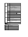
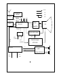
5、 Block Diagram………………………………………………………………34
6、 Schematic Diagram…………………………………………………………35
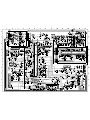
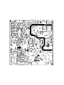
7、 PCB Layout…………………………………………………………………36
8、 Explode Diagram……………………………………… …………………37
This manual is the latest at the time of printing, and does not
include the modification which may be made after the printing, by
the constant improvement of product

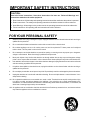
WARNING: TO REDUCE RISK OF FIRE OR ELECTRIC SHOCK, DO NOT
EXPOSE THIS APPLIANCE TO RAIN OR MOISTURE.
CAUTION: TO REDUCE THE RISK OF
ELECTRICAL SHOCK, DO NOT REMOVE
COVER (OR BACK). NO USER SERVICEABLE
PARTS INSIDE. REFER SERVICING TO
QUALIFIED SERVICE PERSONNEL.
The lighting flash with arrowhead symbol, with an equilateral triangle is intended to
alert the user to the presence of uninsulated voltage within the products
enclosure that may be of sufficient magnitude to constitute a risk of electric shock to
the person.
The exclamation point within an equilateral triangle is intended to alert the user to the
presence of important operating and maintenance (servicing) instructions in the
literature accompanying the appliance.
CAUTION:
Use of controls, adjustments or procedures other than those specified herein may result in
hazardous radiation exposure.
CAUTION
RISK RISK OF OF ELECTRIELECTRICC
SHOCK SHOCK DO DO NOT NOT OPEN.OPEN.
2
dangerous

3
FOR YOUR PERSONAL SAFETY
1. When the power cord or plug is damaged or frayed, unplug this television set from the wall outlet and refer servicing to
qualified service personnel.
2. Do not overload wall outlets and extension cords as this can result in fire or electric shock.
3. Do not allow anything to rest on or roll over the power cord, and do not place the TV where power cord is subject to
traffic or abuse. This may result in a shock or fire hazard.
4. Do not attempt to service this television set yourself as opening or removing covers may expose you to dangerous
voltage or other hazards. Refer all servicing to qualified service personnel.
5. Never push objects of any kind into this television set through cabinet slots as they may touch dangerous voltage
points or short out parts that could result in a fire or electric shock. Never spill liquid of any kind on the television set.
6. If the television set has been dropped or the cabinet has been damaged, unplug this television set from the wall outlet
and refer servicing to qualified service personnel.
7. If liquid has been spilled into the television set, unplug this television set from the wall outlet and refer servicing to
qualified service personnel.
8. Do not subject your television set to impact of any kind. Be particularly careful not to damage the picture tube surface.
9. Unplug this television set from the wall outlet before cleaning. Do not use liquid cleaners or aerosol cleaners. Use a
damp cloth for cleaning.
10.1. Do not place this television set on an unstable cart, stand, or table. The television set may fall, causing serious injury
to a child or an adult, and serious damage to the appliance. Use only with a cart or stand recommended by the
manufacturer, or sold with the television set. Wall or shelf mounting should follow the manufacturer s instructions, and
should use a mounting kit approved by the manufacturer.
10.2. An appliance and cart combination should be moved with care. Quick stops, excessive force, and uneven surfaces
may cause the appliance and cart combination to overturn.
CAUTION:
Read all of these instructions. Save these instructions for later use. Follow all Warnings and
Instructions marked on the audio equipment.
1. Read Instructions- All the safety and operating instructions should be read before the product is operated.
2. Retain Instructions- The safety and operating instructions should be retained for future reference.
3. Heed Warnings- All warnings on the product and in the operating instructions should be adhered to.
4. Follow Instructions- All operating and use instructions should be followed.
IMPORTANT SAFETY INSTRUCTIONS

4
PROTECTION AND LOCATION OF YOUR SET
11. Do not use this television set near water ... for example, near a bathtub, washbowl, kitchen sink, or laundry tub, in a
wet basement, or near a swimming pool, etc.
Never expose the set to rain or water. If the set has been exposed to rain or water, unplug the set from the wall
outlet and refer servicing to qualified service personnel.
12. Choose a place where light (artificial or sunlight) does not shine directly on the screen.
13. Avoid dusty places, since piling up of dust inside TV chassis may cause failure of the set when high humidity persists.
14. The set has slots, or openings in the cabinet for ventilation purposes, to provide reliable operation of the receiver, to
protect it from overheating. These openings must not be blocked or covered.
Never cover the slots or openings with cloth or other material.
Never block the bottom ventilation slots of the set by placing it on a bed, sofa, rug, etc.
Never place the set near or over a radiator or heat register.
Never place the set in enclosure, unless proper ventilation is provided.
PROTECTION AND LOCATION OF YOUR SET
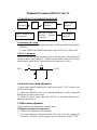
15.1. If an outside antenna is connected to the television set, be sure the antenna system is grounded so as to provide some
protection against voltage surges and built up static charges, Section 810 of the National Electrical Code, NFPA No.
70-1975, provides information with respect to proper grounding of the mast and supporting structure, grounding of the
lead-in wire to an antenna discharge unit, size of grounding conductors, location of antenna discharge unit, connection
to grounding electrode, and requirements for the grounding electrode.
15.2. Note to CATV system installer : (Only for the television set with CATV reception)
This reminder is provided to call the CATV system attention to Article 820-40 of the NEC that provides
guidelines for proper grounding and, in particular, specifies that the cable ground shall be connected to the grounding
system of the building, as close to the point of cable entry as practical.
16. An outside antenna system should not be located in the vicinity of overhead power lines or other electric lights or power
circuits, or where it can fall into such power lines or circuits. When installing an outside antenna system, extreme care
should be taken to keep from touching such power lines or circuits as contact with them might be fatal.
17. For added protection for this television set during a lightning storm, or when it is left unattended and unused for long
periods of time, unplug it from the wall outlet and disconnect the antenna. This will prevent damage due to lightning
and power-line surges.
ANTENNA
LEAD- IN WIRE
ANTENNA DISCHARGE
UNIT (NEC SECTION
810-20)
GROUNDING
CONDUCTORS
(NEC SECTION810-21)
GROUND CLAMPS
POWER SERVICE GROUNDING
ELECTRODE SYSTEM
(NEC ART 250. PART H)
ELECTRIC SERVICE
EQUIPMENT
GROUND CLAMP
NEC-NATIONAL ELECTRICAL CODE
EXAMPLE OF ANTENNA GROUNDING AS PER
NATIONAL ELECTRICAL CODE
EXAMPLE OF ANTENNA GROUNDING AS PER NATIONAL ELECTRICAL CODE INSTRUCTIONS
a built-in
installer s

OPERATION OF YOUR SET
18.
This television set should be operated only from the type of power source indicated on the marking label.
If you are not
sure of the type of power supply at your home, consult your television dealer or local power company. For television
sets designed to operate from battery power, refer to the operating instructions.
19. If the television set does not operate normally by following the operating instructions, unplug this television set from the
wall outlet and refer servicing to qualified service personnel. Adjust only those controls that are covered in the operating
instructions as improper adjustment of other controls may result in damage and will often require extensive work by a
qualified technician to restore the television set to normal operation.
20. When going on a holiday : If your television set is to remain unused for a period of time, for instance, when you go on
a holiday, turn the television set and unplug the television set from the wall outlet.
IF THE SET DOES NOT OPERATE PROPERLY
21. If you are unable to restore normal operation by following the detailed procedure in your operating instructions,
do not attempt any further adjustment. Unplug the set and call your dealer or service technician.
22. Whenever the television set is damaged or fails, or a distinct change in performance indicates a need for
service, unplug the set and have it checked by a professional service technician.
23. It is normal for some TV sets to make occasional snapping or popping sounds, particularly when being
turned on or off. If the snapping or popping is continuous or frequent, unplug the set and consult your
dealer or service technician.
FOR SERVICE AND MODIFICATION
24. Do not use attachments not recommended by the television set manufacturer as they may cause hazards.
25. When replacement parts are required, be sure the service technician has used replacement parts specified
by the manufacturer that have the same characteristics as the original part. Unauthorized substitutions
may result in fire, electric shock, or other hazards.
26. Upon completion of any service or repairs to the television set, ask the service technician to perform
routine safety checks to determine that the television is in safe operating condition.
5
off

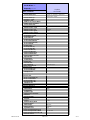
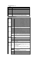
PFS2 FORMAT-1 Report
Date2004-6-3 15:49
ProductView......:
Report by............:
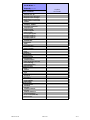
Specs / Products
MasterData
Customer Id
JET LTDA(CHILE)
Version
1
Status
Locked
12NC
Brand
HYUNDAI
EAN
\
UPC
\
Rece
p
tion
+Tunin
g
-
p
resets/channels
181, Full-Cable
+Tunin
g
- technolo
gy
PLL
+Tunin
g
- Indication
Full-Cable
+Fre
q
Bands
Freq
+Channels
+IF Fre
q
45.75M
+TV S
y
stems Off Air/Cabl
e
NTSC-M, PAL MN
+Add S
y
stems Ext In
4.43 NTSC, 4.43PAL
+TV S
y
stems Multi
PAL NTSC
+Sound S
y
stems
AV STEREO
Picture - Processin
g
+Scan
Standard
+Scan Modes
4:3
+Wide Screen Switchin
g
+Combfilter
+Picture Control
Brightness, Color, Contrast, Tint, Sharpness
Con Var, Smart pict 4 modes
+Pict Enhancement
Blue Mute
+Pict Noise Reduction
Yes
Picture - Dis
p
la
y
+Dis
p
la
y
T
ype
+Screen Format
+Size
(
Visual
)
" - size/vis. cm
21"
+Deflection S
y
stem
(
CRT onl
y)
+Tube Technolo
gy
(
CRT onl
y)
+CRT Defl
+CRT Gun
+CRT Ma
g
n field
+Resolution
+Coatin
g
(
onl
y
for D.V. sets
)
+White Point
Sound
+Leaflet Power
+RMS Power Intern
2X3W
+RMS Power Extern
+Surround Sound
' +Sound Features
Mute, Smart sound(4 modes)
+Sound Control
Volume
Sound - S
p
eakers
+S
p
eaker confi
g
uration
2 speakers
+S
p
eakers used
+S
p
eaker Size
User Interface
+Interface Name
21189
+Voice Control
+Menu
Cursor Control
+Menu Colours
+Menu Lan
g
ua
g
es
Spanish, English
+Special Features
Favorite channel, Notebook,
Biological,Calendar
+O
p
erational Features
+PP Features
+Tuning/Install Features
Auto Cable/ Auto select. Auto channel Prog,
Cable/Antenna select, Factory Mode,
Language Selection, Service Mode
Product:
HU-TV2117
2004-6-3 16:13 1465 PFS 1 of 3

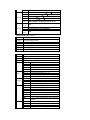
Date2004-6-3 15:49
ProductView......:
Report by............:
Specs / Products
Product:
HU-TV2117
+Clock/Timer Functions
sleep timer
+Local Controls Front
Channel +/-, Volume+/-, Mains(Tact
Switch), Menu, TV/AV
+Local Controls To
p
+Indicators - screen
+Indicators - front
+Numb of Loc Cont
(
incl Mains
)
+Number of Ind.
(
incl Mains
)
+Local Controls
(
Old
)
Remote Control
+Remote Control - sco
p
e
TV
+Remote Control - t
yp
e
Standard
+Remote Control - t
yp
en
r
RC115
+Remote Control - features
Connectors Rea
r
+Scart RGB+Y/C+CVBS
+Scart RGB+CVBS
+Scart CVBS+Y/C
+Com
p
onent In
(
Y/U/V
)
Cinch
+In Y/C+Cinch
(
CVBS+St
)
x
+In Y/C+Cinch
(
CVBS+Mo
)
+In Y/C+Cinch
(
St
)
+In BNC
(
CVBS
)
+In Cinch
(
CVBS+St
)
+In Cinch
(
CVBS+Mo
)
+Out Cinch
(
CVBS+St
)
x
+Out Cinch
(
CVBS+Mo
)
+Out Cinch Audio Stereo
+Out Cinch Audio Mono
+Out Cinch Dolb
y
Surround
+Di
g
Audio Out
+Louds
p
eakers
+Control Busses
+Feature Slot
+ITV Smart Port
+Terr. Antenna in
75 Ohms(F type)
Guide + IR Blaster Jack
Connectors Fron
t
+In Cinch
(
CVBS + St
)
+In Cinch
(
CVBS+Mo
)
+Head
p
hone Out
Connectors Side
+In Y/C + Cinch
(
CVBS+St
)
+In Y/C + Cinch Stereo
+In Cinch
(
CVBS + St
)
x
+IN Cinch
(
CVBS + Mo
)
+Head
p
hone Out
Connectors To
p
Connectors Mechanical
St
y
lin
g
+Cabinet Name
21189
+Confi
g
uration
+Gra
p
hics/Lo
g
o's
+Cabinet Colour and Finish
+Mechanics
+S
p
eaker Visibilit
y
General
+Se
g
ment
+Chassis
M123A
+Software Deliver
y
Mode
+Software Version
+Mains Volta
g
e
110-240V
+Mains Fre
q
uenc
y
50 / 60 Hz
+T
yp
e Mains Cord
VDE
Power Consum
p
tion
(
P
)
TV in On
Power Consum
p
tion SB in Watts
less than 3W
Power Consum
p
tion Semi SB in W
+Power in "ON" for
2004-6-3 16:13 1465 PFS 2 of 3

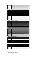
Date2004-6-3 15:49
ProductView......:
Report by............:
Specs / Products
Product:
HU-TV2117
+Power in Standb
y
for
+Power in "OFF" for
Wei
g
ht
(
P
)
TV
(
incl. Packa
g
in
g)
Wei
g
ht
(
P
)
TV
(
excl. Packa
g
e
)
Wei
g
ht AVUnit excl Packa
g
in
g
+INDICATION on BACKCOVE
R
+Channel
Final E
q
ui
p
ment
+Packa
g
in
g
- methods
+Documents and manuals
+Lan
g
ua
g
es DFU
+Cables Su
pp
lied
+Antenna Su
pp
lied
+Stand Su
pp
lied
+Aux E
q
ui
p
m Su
pp
lied
Packa
g
in
g
- width cm
Packa
g
in
g
- hei
g
ht cm
Packa
g
in
g
- de
p
th cm
Miscellaneous
+EAN Indication
+A
pp
robation
+Tests
+Local Inte
g
ration
V
arious Perf. Param.
+Service Call-Rate
PIP/POP
+T
ype
+Features
Di
g
ital Rece
p
tion
+Transmission
Built-in Data S
y
stem
+Text Standard
+
(
Tele
)
text Features
+Nbr bck
g
rnd
p
a
g
e / Mem Size
+Text Technolo
gy
+Di
g
ital Data handlin
g
+Pro
g
ram Guide
Built-in Clock/Timer
+T
ype
+Features
Built-in Radio
+T
ype
Built-in PC dis
p
la
y
+PC S
y
nch
+PC Control
Built-in DVD drive
+T
yp
e of Medium
+T
yp
e of Dec
k
Phased Out Items
+Tuner/Frontend
+Sensitivit
y
+CRT EHT
+Li
g
htnin
g
Protection
+Accoun
t
+XX
(
Radio Antenna in
)
+Non Volatile Memor
y
+In Y/C + Cinch
(
CVBS+Mo
)
Version of deck
2004-6-3 16:13 1465 PFS 3 of 3

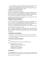
Alignment Procedure of M123A Color TV
1. FLOWCHART OF ALIGNMENT PROCEDURE
2 Adjustment of B+ voltage
1) Apply 120VAC(±5V) to mains power input, and Philips standard testing pattern
to RF input.
2) Adjust VR830 in STANDARD mode until voltage at TP2 (B+) is 108V ±0.5V.
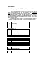
3. RF AGC adjustment
Observe monitor the collector waveform of Q101 with the probe of Oscilloscope as
illustration below. Select channel 2 (>70dB) from the antenna input. Enter D-mode,
select menu6 to adjust RFAGC item until the monitor peak value to 0.8V
p-p
.
IN60
3Pf
4. Screen & Focus voltage adjustment
Apply pattern signal in normal status, enter D-mode, press “TV/AV” button to turn
off the vertical output.
Adjust the SCRREEN switch on the flyback transformer to make a horizontal
shining line just visible on the screen.
Turn on the vertical output, adjust the “FOCUS” on the flyback transformer to
obtain the optimum focus.
5. White balance adjustment
1)Apply the black and white pattern in normal status;
2)Alignment of normal color temperature
Change Color Temperature to normal status
Use a color analyzer to measure the black side of the screen. By changing the
value of RC, GC and BC, set the reading of the color analyzer to X=285, Y=295.
B+
adjustment
AGC
Screen & Focus
adjustment
White balance
adjustment
Sub-brightness
adjustment
Pincushion correction &
Horizontal Amplitude
adjustment
Center & Amplitude an
d
OSD adjustment
INPUT OUTPUT

Use a color analyzer to measure the white side of the screen. By changing the
value of GD, BD, set the reading of the color analyzer to X=285, Y=295.
Separately set the brightness and contrast from min. to max., repeat the step 2 and
3 until the reading of the color analyzer is correct.
3)Alignment of warm color temperature
Change Color Temperature to warm status
Use a color analyzer to measure the black side of the screen. By changing the value
of RC-W, GC-W and BC-W, set the reading of the color analyzer to X=294, Y=303.
Use a color analyzer to measure the white side of the screen. By changing the value
of GD-W, BD-W set the reading of the color analyzer to X=294, Y=303.
Separately set the brightness and contrast from min. to max., repeat the step 2 and 3
until the reading of the color analyzer is correct.
4)Alignment of cold color temperature
Change Color Temperature to cold status
Use a color analyzer to measure the black side of the screen. By changing the value
of RC-C, GC-C BC-C , set the reading of the color analyzer to X=279, Y=286.
Use a color analyzer to measure the white side of the screen. By changing the value
of GD-C, BD-C, set the reading of the color analyzer to X=279, Y=286.
Separately set the brightness and contrast from min. to max., repeat the step 2 and 3
until the reading of the color analyzer is correct
Note: Provided the production line is equipped with the self- White balance
adjusting equipment, white balance of M123A chassis can be adjusted automatically
as following: Press “I
2
C BUS” button under factory mode, the TV set will adjust
automatically.
6. Adjustment of Sub-brightness,
Apply the Grey-scale/Color bar (NTSC signal) to the AV input, in normal status.
Select BRTC to adjust the sub-brightness, until that the 2
nd
dark bar of 8 level
Grey scale just can be seen.
7. PAL picture geometric adjustment
menu 3
HPOS6/HPOS5 HZ horizontal center of 60/50 HZ Source
Menu 2
HIGH6/HIGH5(vertical amplitude)
VCEN5/VCEN6(position of vertical center)
VP60/VP50 vertical position
VLIN6/VLIN5 vertical linearity
VSC6/VSC5 V-S Correction
8 initialization
press sound-effect under factory mode, the set will initialize, until “OK” appears
on the screen which means the initialization is finished. After initialization, the set
will quit factory mode automatically.

Factory settings
D-mode:
Enter D-Mode by pressing D-Mode ON/OFF key, and then you can enter the D-mode.
S-mode:
Enter S-Mode by pressing VOLUME DOWN key on the unit until the
volume decrease to minimum level, then press the DISPLAY key on the remote
handset (don’t release the volume key) and you can enter S- mode.
After enter D-mode or S-mode, press OK, then press program up/down to
select menu from menu 1 to menu 22, press OK to enter the menu, press program
up/down to select item, press volume up/down to adjust the setting. Press D-mode
again to quit factory mode.
You can also enter menu 1 to menu 19 directly by pressing digital button 1~9,
0, notebook, CAP, Display, Sleep, Calendar, System/INS, Favorite, Return, Picture.
Menu 1 (Remote key: “1”)
Item
Remark
RC
R cut-off setting
GC G cut-off setting
BC B cut-off setting
GD G drive setting
BD B drive setting
Menu 2 (Remote key: “2”))
Item
Remark
HIGH5
Height (50Hz)
VP50 Vertical position (50Hz)
VLIN5 Vertical linearity (50Hz)
VSC5 Vertical S correction (50Hz)
VBLK5 Vertical blanking start & stop [1C, bit 3 ~ 0]
VCEN5 Vertical center (50Hz)
Menu 2 (Remote key: “2”)
Item
Remark
HIGH6
60Hz height
VP60 Vertical position
VLIN6 60Hz Vertical linearity
VSC6 Vertical S correction (60Hz)
VBLK6 Vertical blanking start & stop [1CH, bit 3 ~ 0]
VCEN6 Vertical center (60Hz)
Menu 3 (Remote key: “3”)
Item
Remark
HPOS5
Horizontal position (50Hz)
Menu 3 (Remote key: “3” )
Item
Remark
HPOS6
Horizontal position (60Hz)

Menu 4 (Remote key: “4”)
Item
Remark
CNTX Maximum contrast
CNTN Minimum contrast
BRTX Maximum brightness
BRTN Minimum brightness
COLX Maximum color
COLN Minimum color
TNTX Maximum tint level
TNTN Minimum tint level
Menu 5(Remote key: “5”)
Item
Remark
BRTC
50% brightness
COLC
50% color
COLP Color level for PAL
SCOL UV gain [06H, bit 6 ~ 4]
SCNT Sub-contrast [06H, bit 3 ~ 0]
CNTC 50% contrast
TNTCT 50% tint level (TV mode)
TNTCV 50% tint level (AV mode)
Menu 6(Remote key: “6” )
Item
Remark
ST3
50% Sharpness (TV mode, 3.58 system)
SV3 50% Sharpness (AV mode, 3.58 system)
SV4 50% Sharpness (AV mode, other system)
SVD 50% Sharpness (DVD mode)
ASSH Asymmetric sharpness [04H, bit 7 ~ 5]
SHPX Maximum sharpness
SHPN Minimum sharpness
Menu 7( Remote key: “7”)
Item
Remark
Bit 0,Bit 1
under factory mode : 00,11, STD 01:IRC
10:HRC
Bit 2
STD, IRC,HRC 1: user control 0: under factory mode
Bit 3
1: forbid CATV 95/96/97
Bit 4
Bit 5 1: have CCD
Bit 6 1:have V-CHIP
MOD1
Bit 7
1:as Monitor no TV mode
Bit 0,Bit 1
Speed of searching
Bit 2
High sensitivity 1 yes 0:no
Bit 3
Volume control 1:PWM
Bit 4
AV1:
1 yes 0:no
Bit 5
AV2:
1 yes 0:no
Bit 6
YUV: 1 yes 0:no
MOD2
Bit 7
Bit 0
Bit 1
MOD3
Bit 2

Bit 3
Bit 4
Bit 5
TV MSP AVL: 1: yes
Bit 6
AV MSP AVL 1:yes
Bit 7
MONO+SAP 1 yes 0 no
Bit 0 When blue background off (mute pin of CPU): 0: audio
mute on 1: audio mute off
Bit 1 When blue background off (external mute pin of CPU):
0: audio mute on 1: audio mute off
Bit 2 When change channel: 0: picture mute off 1: picture
mute on
Bit 3 Switch between TV and CATV or change channel in the
tune menu 1: picture mute on
Bit 4 AFT –MUTE 1: ON,
Bit 5 Polarity of Tint
Bit 6
OPT
Bit 7
Bit 0 TDA98500 0:no 1:yes
Bit 1 MSP34xx 0:no 1:yes
Can’t be set to 1 at
the same time
Bit 2 1: AV audio out mute when volume is zero or mute
Bit 3 1: decreasing contrast when menu on
Bit 4 1: OSD don’t disappear automatically
Bit 5 1:biological
Bit 6 0: CH LOCK W/O V-CHIP
OPTM1
Bit 7 When turn on 0:child lock off 1:child lock on
Bit 0
Bit 1
Bit 2
Power on mode: 00: standby 01:previous
10&11: force power on
Bit 3 Hotel mode 1:on 0: off
Bit 4
Bit 5
Power on under hotel mode
00: TV | 01: Video1 | 02: TV2 | 03: Last
Bit 6 1: under factory mode turn off the set by the remote or
power off, then turn on or power on, the set enter
factory mode
OPTM2
Bit 7 1: D-MODE
HDCNT
HSTOP
Menu 8 (Remote key: “8” )
Item
Remark
RFAGC
RFAGC [12H, bit 5 ~ 0]
BRTS
Sub brightness for SECAM
OSD
Horizontal position of OSD
OSDF OSD PLL DATA
CCD OSD
Horizontal position of CCD OSD
CCD OSDF PLL DATA of CCD OSD
TXCX
OSD intensity when maximum contrast
RGCN
OSD intensity when minimum contrast

Menu 9(Remote key: “9”)
Item
Remark
V01 Volume 1
V25 Volume 25
V50 Volume 50
V100 Volume 100
VOLMAX
Max volume under hotel mode
CURTCEN
Center of the curtain
VOLX
Output gain of PIN28 of TMPA8823 or MSP34x5
PWTM When use PWM to mute and no sound when changing
channel, this item should be minimum as posible
Menu 10(Remote key: “0”)
Item
Remark
Bit 0
TV Color system AUTO 1 yes 0 no
Bit 1
TV Color system NTSC358 1 yes 0 no
Bit 2
TV Color system PALM 1 yes 0 no
Bit 3
TV Color system PALN 1 yes 0 no
Bit 4
AV Color system AUTO 1 yes 0 no
Bit 5
AV Color system NTSC358 1 yes 0 no
Bit 6
AV Color system PALM 1 yes 0 no
MDOE4
Bit 7
AV Color system PALN 1 1 yes 0 no
Bit 0
English: 1 yes 0 no
Bit 1
French: 1 yes 0 no
Bit 2
Portuguese: 1 yes 0 no
Bit 3
Spanish : 1 yes 0 no
Bit 4
AV Color system PAL443 1 1 yes 0 no
Bit 5
AV Color system NTSC443 1 1 yes 0 no
Bit 6
AV AUTO 1:AUTO1(PAL443 NTSC358
NTSC443) 0:AUTO2(NTSC358 PALM PALN)
MDOE5
Bit 7
Bit 0
1:auto search function of the menu key on the front
panel
Bit 1 1: curtain when turn on the set
Bit 2 1: curtain when turn off the set
MDOE6
Bit3~ 7
V-mute timing when changing channel(01H = 8ms)
max :248ms
Bit 0
Bit 1
When sound mode change
11:change to the corresponding mode and ODS
display automatically
01: change to the corresponding mode and ODS
doesn’t display
00,10: change to MONO ODS doesn’t display
Bit 2
Bit 3
00 10 detect BTSC and Korea stereo
automatically
01 force BTSC 11 force Korea stereo
Bit 4
FINE, 1:yes 0 no
Bit 5
50Hz block 1:yes 0 no
MDOE7
Bit 6 1: contrast change when power on

Bit 7
Bit 0
America V-CHIP standard 1 yes 0 no
Bit 1
Canadian V-CHIP 1 yes 0 no
Bit 2
UNRATED 1 yes 0 no
Bit 3
NO RATING 1 yes 0 no
MDOE8
Bit 4
~Bit 7
Time setting for curtain when turn on the set
Bit 0
~Bit 2
N/A
Bit 3
S-VIDEO ,0:parallel to AV1 1: parallel to AV2
Bit 4
1:sound effect w/o mpx (MSP3465)
MDOE9
Bit 5
~Bit 7
N/A
Menu 12(Remote key: “CAP”)
Item
Remark
OSD2 OSD Horizontal Position
OSDF2 OSD PLL DATA except
PYNX Normal H.SYNC max
PYNN Normal H.SYNC min
PYXS Search H.SYNC max
PYNS Search H.SYNC min
Menu 13 (Remote key: “Display” )
Item
Remark
CLTM
TV mode
CLVO Video mode
CLVS s-video mode
Bit 2 ~ 0 YDL [15H, bit 2 ~ 0] (-40ns~240ns)
Bit 4 ~ 3 NTSC matrix [03H, bit 7 ~ 6] (N1,N2,DVD)
Bit 5 C gamma [02H, bit 7] (color gamma on/off)
Bit 6 P/N ID [17H, bit 4] (PAL/NTSC killer sensit.)
Bit 7 FID [17H, bit 3] (Killer off)
Bit 1 ~ 0
ABL gain [16H, bit 5 ~ 4]
Bit 3 ~ 2 ABL start point [16H, bit 7 ~ 6]
Bit 4 WPS [00H, bit 7]
ABL
Bit 5 OSD ABCL [16H, bit 3]
Bit 1 ~ 0 Black stretch [15H, bit 4 ~ 3]
Bit 3 ~ 2 Y gamma [15H, bit 6 ~ 5]
Bit 5 ~ 4 OSD level [16H, bit 1 ~ 0]
DCBS
Bit 7 Blank switch [0CH, bit 7]
Bit 0
Over modulation [13H, bit 5]
Bit 1
Aft window size [13H, bit 6]
Bit 2
Buzz reducer [13H, bit 7]
Bit 3 Audio gain switch [14H, bit 7]
Bit 4
Bit 5
Bit 6
FLG0
Bit 7
1: VCO adjust automatically when changing
channel
Bit 0
CW SW [06H, bit 7], control PIN26,
Bit 1
Slice level [1EH, bit 6]
Bit 2
Mix gain [15H, bit 7]
FLG1
Bit 3
V ramp bias [1DH, bit 4]

Bit 4
Bit 5
Bit 6
Bit 7
SLO f0 shift(test only)
Menu 14(Remote key: “sleep)
Item
Remark
HAFC
Bit 1 ~ 0 AFC gain (TV mode) [1CH, bit 5 ~ 4]
Bit 3 ~ 2 AFC gain (AV mode) [1CH, bit 5 ~ 4]
AGCC
NOIS
ONTM V-mute timing when power on (01H = 16ms)
NSHP Decreased level of sharpness when noise reduction is on
PVLVL X-ray protection start point (00H Æ 0V & FFH Æ 5V)
PLMT (01H = 8ms)
Menu 15 (Remote key: “Calendar”)
Item
Remark
RC-C
R cut-off setting (for cool color temperature)
GC-C G cut-off setting (for cool color temperature)
BC-C B cut-off setting (for cool color temperature)
GD-C G drive setting (for cool color temperature)
BD-C B drive setting (for cool color temperature)
Menu 16 (Remote key: “System/INS” )
Item
Remark
RC-W
R cut-off setting (for warm color temperature)
GC-W G cut-off setting (for warm color temperature)
BC-W B cut-off setting (for warm color temperature)
GD-W G drive setting (for warm color temperature)
BD-W B drive setting (for warm color temperature)
YUVGC YUV R cut-off
YUVBC YUV B cut-off
Menu 17 (Remote key: “FAV” )
Item
Remark
D-COL
Dynamic color
D-BRI
Dynamic brightess
D-CON
Dynamic contrast
D-SHP
Dynamic sharpness
Menu 18 (Remote key: “Return” )
Item
Remark
S-COL
Standard color
S-BRI
Standard brightess
S-CON
Standard contrast
S-SHP
Standard sharpness
Menu 19 (Remote key: “Picture” )

Item
Remark
M-COL
Mild color
M-BRI
Mild brightess
M-CON
Mild contrast
M-SHP
Mild sharpness
Menu 20: no shortcut key
Item
Remark
SEG_POINT1
Highest frequency of VHFL
SEG_POINT2
Highest frequency of VHFH
DATA_VL
VHFL bandswitch BB
DATA_VH
VHFH bandswitch BB
DATA_UF
UHF bandswitch BB
SPE_POS1
The channel number treated specially
SPE_DATA1
Bandswitch in which the special channel BB
SENSI_ON
SENSI_OFF
Menu 21: no shortcut key
Item
Remark
THEATER-BAS
Theater bass
THEATER-TRE
Theater treble
CONCERT-BAS
Concert bass
CONCERT-TRE
Concert treble
BROCAST-BAS
Brocast bass
BROCAST-TRE
Brocast treble
Menu 22: no shortcut key
Item
Remark
VOL_MAI Volume Loudspeaker
GATE
Carrier-Mute
VOL-OUT
AV output gain
AV GAIN
AV input Gain
Note:
Provided the production line is equipped with the self-adjusting equipment, The adjusted item
should be based on the result by such equipment.
There’s difference between PAL geometric/OSD adjustment and NTSC geometric/OSD
adjustment. PAL adjustment must be done before NTSC adjustment.

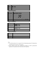
24V
B
R
R
+9
V
U Y Y
SIF OUT
CVBS/Y
E
2
PROM
24C08
SDA SCL
AMP
TDA7057AQ
L
R
MCU+VCD
TMPA8823
CRT
Video
amplifie
Horizontal output
Vertical output
STV9302
TUNER
SAWF
+112V
+12
+9V
+5V
4052
AV 1
(VIDEO)
AV 2
(VIDEO)
MSP3425
AV 1
(L,R)
AV 2
(L,R)


Page is loading ...
-
 1
1
-
 2
2
-
 3
3
-
 4
4
-
 5
5
-
 6
6
-
 7
7
-
 8
8
-
 9
9
-
 10
10
-
 11
11
-
 12
12
-
 13
13
-
 14
14
-
 15
15
-
 16
16
-
 17
17
-
 18
18
-
 19
19
-
 20
20
-
 21
21


