
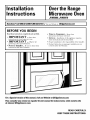
Installation
Instructions
Overthe Range
Microwave Oven
JVM3_O, JVM36_
I Questions?Call800.GECARES(800.432.2737)orVisitour Website at: GEAppliances.com I
BEFORE YOU BEGIN
Read these instructions completely and carefully.
• IMPORTANT - Savethese
instructions for local inspector's use.
• IMPORTANT - Obse,-_eall
governing codes and ordinances.
• Note to Installer - Be sure to leavethese
instructions with the Consumer.
• Note to Consumer - Keep these
instructions for future reference.
• Skill level - Installation of this appliance requires
basic mechanical and electrical skills.
• Proper installation is the responsibility of the installer.
• Product failure due to improper installation is not
covered under the Warranty.
Fora Spanishversionofthismanual, visitour Websiteat GEAppliances.com.
Para consultaruna versionen espafioldeeste manualde instrucoiones,visitenuestrositio
de internet GEAppliances.com.
READ CAREFULLY.
KEEP THESE INSTRUCTIONS.

Installation Instructions
CONTENTS
General information
Important Safety Instructions .................................. 3
Electrical Requirements .......................................... 3
Hood Exhaust ...................................................... 4, 5
Damage - Shipment/Installation .............................. 6
Parts Included .......................................................... 6
Tools You Will Need ................................................ 7
Mounting Space ...................................................... 7
Step-by-step installation guide
Placement of Mounting Plate ............................ 8-10
Removing the Mounting Plate ...................... 8
Finding the Wall Studs .................................. 8
Determining Wall Plate Location .................. 9
:Migning the Wall Plate ................................ 10
Installation Types .............................................. 11-22
_] Outside Top ............................
Exhaust 12-14
Attach Mounting Plate to Wall ............ 12
Preparation of Top Cabinet ................ 13
Checking for Proper Damper
Operation ............................................ 13
Mount the Microwave Oven ................ 13
Adjust the Exhaust Adaptor ................ 14
Connecting Ductwork .......................... 14
_] Outside Back Exhaust 15-18
Preparing Rear Wall fbr
Outside Back Exhaust .................... 15, 16
Attach Mounting Plate to Wall ............ 16
Preparation of Top Cabinet ................ 16
Adapting Microwave Blower
for Outside Back Exhaust ...................... 17
Mount the Microwave Oven ................ 18
] Recirculating ........................................ 19-22
Attach Mounting Platc to Wall ............ 19
Preparation of Top Cabinet ................ 19
Check Microwave Assembly ................ 20
Adapting Microwave Blower
for Rccirculation .......................... 20, 21
Mount the Microu-ave Oven .......... 21, 22
Installing the Charcoal Filter .............. 22
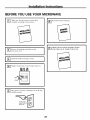
Before You Use Your Microwave .......................... 23
2

Installation Instructions
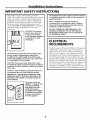
IMPORTANT SAFETY INSTRUCTIONS
This product requires a three-prong grounded
outlet. The installer must perfbrm a ground continuity
check on the power outlet box before beginning the
installation to insure that the outlet box is properly
grounded. If not properly grounded, or if the outlet
box does not meet electrical requirements noted
(under ELECTRICAL REQUIREMENTS), a qualified
electrician should be employed to correct any
deficiencies.
CAUTION: For personal
safety, remove house fuse
or open circuit breaker
before beginning installation
to avoid severe or fatal
shock injury.
CAUTION: For personal safety, the mounting surface
must be capable of supporting the cabinet load,
in addition to the added weight of this 63-85 pound
product, plus additional oven loads of up to 50 pounds
or a total weight of 113-135 pounds.
CAUTION: For personal safety, this product cannot
be installed in cabinet arrangements such as an island or
a peninsula. It must be mounted to BOTH a top cabinet
AND a wall.
NOTE: For easier installation and personal safety, it is
recommended that two people install this product.
IMPORTANT--PLEASE READ CAREFULLY. FOR
PERSONAL SAFETY, THIS APPLIANCE MUST BE
PROPERLY GROUNDED TO AVOID SEVERE OR
FATAL SHOCK.
The power cord of this
appliance is equipped with
a 3-prong (grounding)
plug which mates with a
standard three-prong
(grounding) wall receptacle
to minimize the possibility
of electric shock hazard
from this appliance.
insureproper
groundexists
beforeuse
You should have the wall receptacle and circuit checked
by a qualified electrician to make sure the receptacle is
properly grounded.
Where a standard two-prong wall receptacle is
encountered, it is very important to have it replaced
with a properly grounded three-prong wall receptacle,
installed by a qualified electrician.
DO NOT, UNDER ANY CIRCUMSTANCES, CUT,
DEFORM, OR REMOVE ANY OF THE PRONGS
FROM THE POWER CORD. DO NOT USE WITH
AN EXTENSION CORD.
ELECTRICAL
REQUIREMENTS
Product rating is 120 volts AC, 60 Hertz, 15 amps, and
1..58 kilowatts. This product must be connected to a
supply circuit of the proper voltage and frequency:
Wire size must conform to the requirements of the
National Electrical Code or the prevailing local code
for this kilow-att rating. The power supply cord and
plug should be brought to a separate 15 to 20 ampere
branch circuit single grounded outlet. The outlet box
should be located in the cabinet above the microwave
oven. The outlet box and supply circuit should be
instMled by a qualified electrician mid confbrm to the
National Electrical Code or the prevailing local code.
3

Installation Instructions
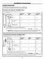
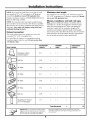
HOOD EXHAUST
NOTE: Read these next two pages only if you plan to vent your exhaust to the
outside. If yon plan to recirculate the air back into the room, proceed to page 6.
1
OUTSIDE TOP EXHAUST (EXAMPLE ONLY)
The fbllowing chart describes an example of one possible
ductwork installation.
DUCT PIECES
RoofCap
12 Ft.StraightDuct
(6"Round)
RectangulaFto-Round
TransitionAdaptor*
EQUIVALENT
LENGTH
24 Ft.
12 Ft.
x
5 Ft. x
Equivalentlengthsofductpiecesarebasedonactualtestsand
reflectrequirementsforgoodventingperformancewith anyvent hood.
NUMBER
USED
(1)
(1)
(1)
EQUIVALENT
= LENGTH
24 Ft.
12Ft.
5 Ft.
41 Ft.
Total Length =
* IMPORTANT: If a rectangular-to-round transition adaptor is used, the bottom corners of the damper
will have to be cut to fit, using the tin snips, in order to allow free movement of the damper.
OUTSIDE BACK EXHAUST (EXAMPLE ONLY)
The following chart describes an example of one possible
ductwork installation.
EQUIVALENT
f ,_ DUCT PIECES LENGTH* x
Wall Cap 40 Ft. x
3 Ft.StraightDuct 3 Ft. x
j 3_A"x 10"Rectangular)
(_ 90° Elbow 10Ft. x
NUMBER EQUIVALENT
USED = LENGTH
(1) 40 Ft.
(1) 3Ft.
(2) 20 Ft.
Equivalentlengthsofductpiecesarebasedonactualtestsand
reflectrequirementsfor goodventingperformancewith anyventhood.
Total Length = 63 Ft.
NOTE: For back exbaust, care sbould be taken to align exhaust witb space between studs, or wall should be prepared
at the time it is constructed by leaving enough space between the wall studs to accommodate exhaust.
4

Installation Instructions
NOTE: If you need to install ducts, note that the total
duct length of 3¼" x 10" rectangular or 6" diameter
round duct should not exceed 140 equivalent feet.
Outside ventilation requires a HOOD EXHAUST DUCT.
Read the following carefully.
NOTE: It is important that venting be installed using
the most direct route and with as few elbows as possible.
This ensures clear venting of exhaust and helps prevent
blockages. Also, make sure dampers swing freely and
nothing is blocking the ducts.
Exhaust connection:
The hood exhaust has been designed to mate with
a standard 3¼" x 10" rectangular duct.
If a round duct is required, a rectangular-to-round
transition adaptor must be used. Do not use less than
a 6" diameter duct.
Maximum duct length:
For satisfiactory air movement, the total duct length of
3¼" x 10" rectangular or 6" diameter round duct should
not exceed 140 equivalent feet.
Elbows, transitions, wall and roof caps,
etc., present additional resistance to airflow and are
equivalent to a section of straight duct which is longer
than their actual physical size. When calculating the
total duct length, add the equivalent lengths of all
transitions and adaptors plus the length of all straight
duct sections. The chart below sho,a_ you how to calculam
total equivalent ductwork length using the approximam
feet of equivalent length of some typical ducts.
EQUIVALENT NUMBER EQUIVALENT
DUCT PIECES LENGTH x USED = LENGTH
Rectangular4o-Round 5 Ft. x ( ) Ft.
TransitionAdaptor*
.._ WallCap 40Ft. x ( ) Ft.
90° Elbow 10Ft. x ( ) Ft.
45° Elbow 5 Ft. x ( ) Ft.
90° Elbow 25Ft. x ( ) Ft.
J 45° Elbow 5 Ft. x ( ) Ft.
RoofCap 24Ft. x ( ) Ft.
StraightDuct6" Roundor 1 Ft. x ( ) Ft.
3_A" x10" Rectangular
Total Ductwork = Ft.
* IMPORTANT: ira iectangtllat_lo-round Ilansitlon Eqllivalent lengths of(hlt-t pieces at-(" based on actual tests
adaf)tor is !ist-'([, the bottom corllefs of the dall_per arid i-eflect req/llrenlellts _or good Velltillg perf_i-lllarl_e with
_a'ill have to be cut to fit, t_sing the tin snips, in any _ent hood.
order to aIIo_ t_'ee movement of the damper.
5

Installation Instructions
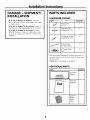
DAMAGE - SHIPMENT/
INSTALLATION
• If the unit is damaged in shipment, return the
unit to the store in which it was bought for repair
or replacement.
• If the unit is damaged by the customer, repair or
replacement is the responsibilib" of the customer.
• If the unit is damaged by the installer (if other
than the customer), repair or replacement must
be made by" arrangement between customer and
installen
PARTS INCLUDED
HARDWARE PACKET
PART QUANTITY
Wood Screws 2
(I/4 _1 X 2")
/ \ Toggle Bolts (and 4
_ wing nuts)(3A6"x 3")
Self-aligning Machine 4
Screws (I/4"-28 x 3W')
Nylon Grommet 2
(for metal cabinets)
28" Pieces of Foam 2
Tape
You will find the installation hardw-are contained in
a packet with the unit. Check to make sure you have
all these parts.
NOTE: Some extra parts are included.
ADDITIONAL PARTS
PART
J--
®
TopCabinet
Template
-r Installation
ms'rJ_4.A_ Instructions
J
Separately
Packed
Grease
Filters
QUANTITY
1
2
6

Installation Instructions
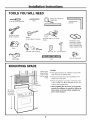
TOOLS YOU WILL NEED
# 1and#2 Phillipsscrewdriver
Pencil
Ruleror tapemeasureand
t edge
Tinsnips(for cutting
damper,if required)
Gloves
Safetygoggles
Scissors
(tocuttemplate,if necessary)
Saw(saber,holeorkeyhole)
Electricdrillwith sA_",VZ'and%"
drillbits
Studfinder or Hammer(optional)
Level
Fillerblocksor scrap
wood pieces,if needed
for top cabinetspacing
(usedon recessedbottom
cabinetinstallationsonly)
Ductandmaskingtape
MOUNTING SPACE
--F--
66" or more
fromthe floor
to thetop of
the microwav
Bottomedgeof
cabinetneedsto
be30" or more
fromthe cooking
surface
plash
NOTES:
• The space bet,a, een the cabinets must be 36"
wide and free of obstructions.
• This microwave oven is for installation over
ranges up to 36" wide.
• If you are going to vent your microwave oven
to the outside, see Hood Exhaust Section for
exhaust duct preparation.
• When installing the microwave oven beneath
smooth, flat cabinets, be careful to follow the
instructions on the top cabinet template for
power cord clearance.
7

Installation Instructions
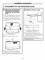
PLACEMENT OF THE MOUNTING PLATE
[_ REMOVING THE MICROWAVE
OVEN FROM THE CARTON/
REMOVING THE MOUNTING
PLATE
[] Remove the installation instructions, filters, glass
tray; and the small hardu-are bag. Do not remove
the Styrofoam protecting the front of the oven.
[] Fold back all 4 carton flaps fiflly against carton
sides. Then carefully roll the oven and carton over
onto the top side. The oven should he resting in
the Svyrofoam.
Styrofoam\
[]Pull the carton up and off the oven.
[] Remove and properly discard plastic bags.
Mounting
Plate
[] Remove the 2 screws from the mounting plate.
This plate will be used as the rear wall template
and for mounting. You may" discard these screws.
I-_ FINDING THE WALL STUDS
[] Find the studs, using one of the following
methods:
A. Stud finder - a magnetic device which
locates nails.
OR
B. Use a hammer to tap lightly across the
mounting surface to find a solid sound.
This will indicate a stud location.
[] After locating the stud(s), find the center by"
probing the wall with a small nail to find the edges
of the stud. Then place a mark halfway between
the edges. The center of any adjacent studs should
be 16" or 24" from this mark.
[]Draw a line down the center of the studs.
THE MICROWAVE MUST BE CONNECTED TO AT
LEAST ONE WALL STUD.
8

Installation Instructions
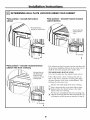
I-_ DETERMINING WALL PLATE LOCATION UNDER YOUR CABINET
Plate position - beneath flat bottom
cabinet
° .°""
MountingPlateTabs
Touchingthe CabinetBottom
II
At least36"
Plate position - beneath framed recessed
cabinet bottom
MountingPlateTabs
Touchingthe Back
Frame
II
30" to Cooktop
Plate position - beneath recessed bottom
cabinet with front overhang
MountingPlatewith
TabsBelowCabinet
Bottomthe Same
Distanceasthe Front
' j OverhangDepth
Your cabinets may have decorative trim that interferes with
the microw-ave installation. Remove the decorative trim to
install the microwave properly and to make it level.
THE MICROWAVE MUST BE LEVEL.
Use a level ro make sure the cabinet bottom is level.
If the cabinets have a front overhang only; with no
back or side frame, install the mounting plate down
the same distance as the front overhang depth. This
will keep the microwave level.
Measure the inside depth of the front overhang.
[] Draw a horizontal line on the back wall an equal
[] distance below the cabinet bottom as the inside
depth of the front overhang.
For this type of installation with front overhang only,
[]align the mounting tabs with this horizontal line, not
touching the cabinet bottom as described in Step D.
II
II
30" to Cooktop
9

Installation Instructions
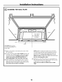
ALIGNING THE WALL PLATE
/
HoleA
CAUTION: Wear gloves
to avoid cutdng fingers on
sharp edges.
) C
I DrawaVertical
I LineonWall
_from Centerof
I TopCabinet
I,
° t _m • • • • • • • • • •
i
AreaE I
I
i
!
[]Draw a vertical line Oll the wall at the center of the
36" wide space.
[] Use the mounting plate, as the template tbr the rear
wall. Place the mounting plate on the wall, making
sure that the tabs are touching the bottom of the
cabinet. Line up the notch and center line on
the mounting plate to the center line on the wall.
[] While holding the mounting plate with one hand,
draw circles on the v_-allat holes A, B, C and D (see
illustration alcove/actual plate marked with arrows).
Four holes must be used for mounting.
NOTE: Holes C and D are inside area E. If neither
C nor D is in a stud, find a stud somewhere in area E
and draw a fifth circle m line up with the stud. It is
important to use at least one wood screw mounted
firmly in a stud to support the weight of the microw-ave.
Set the mounting plate aside.
Drill holes on the circles. If there is a stud, drill a _(;"
hole tor wood screws. For holes that don t hne up with
a stud, drill a 5A"hole for toggle bolts.
NOTE: DO NOT MOUNT THE PLATE AT THIS
TIME.
10

Installation Instructions
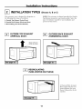
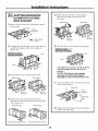
INSTALLATION TYPES (Choose A, B or C)
This microwave oven is designed for adaptation to
the following three types of ventilation:
A. Outside Top Exhaust (Vertical Duct)
B. Outside Back Exhaust (Horizontal Duct)
C. Recirculating (NonWented Ductless)
NOTE: This microwave is shipped assembled for Outside
Top Exhaust (except for non-vented models). Select the
Cr'pe of ventilation required for your installation and
proceed to that section.
_-_ OUTSIDE TOP EXHAUST
(VERTICAL DUCT)
_-_ OUTSIDE BACK EXHAUST
(HORIZONTAL DUCT)
AdaptorinPlacefor
Outside TopExhaust
_-] RECIRCULATING
(NON-VENTED DUCTLESS)
A Charcoal Filter Accessory
Kit is required for the lion-
vented exhaust. (See your
Owner's Manual for the kit
numben)
11

Installation Instructions
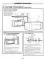
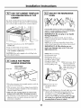
OUTSIDE TOP EXHAUST (Vertical Duct)
INSTALLATION OVERVIEW
AI. Attach Mounting Plate to Wall
A2. Prepare Top Cabinet
33. Check Damper Operation
A4. Mount Microwave Oven
AS. Adjust Exhaust Adaptor
A6. Connect Ductwork
I-_ ATTACH THE MOUNTING
PLATE TO THE WALL
1
Attach the plate m the wall using toggle bolts.
At least one wood screw must be used to attach
the plate m a wall stud.
[]Remove the toggle wings fi'om the bolts.
[] lnsert the bolts into the mounting plate
through the holes designated to go into drywall
and reattach the toggle wings to s/(, onto each bolt.
To use toggle bolts:
Spacingfor Toggles
MoreThanWall
_l.a,a_Thickness
LfoggleWings
Mounting i To le
i gg
Plate l ,lllh BoltII I:k
IIU lq_WBll U i i
Bolt End
[] Place the mounting plate against the wall and
insert the toggle wings into the holes in the wall
to mount the plate.
NOTE: Befbre tightening toggle bolts and wood
screw, make sure the tabs on the mounting plate
touch the bottom of the cabinet when pushed
flush against the wall and that the plate is properly
centered under the cabinet.
CAUTION: Be careful to avoid pinching fingers
between the back of the mounting plate and the wall.
[] Tighten all bolts. Pull the plate away fi'om the wall
to help tighten the bolts.
12

Installation Instructions
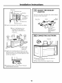
USE TOP CABINET TEMPLATE
FOR PREPARATION OF TOP
CABINET
You need to drill holes for the top support screws, a
hole large enough for the power cord to fit through,
and a cutout large enough for the exhaust adaptor.
%
• Read the instructions on the TOP CzM31NET
TEMPLATE.
• Tape it underneath the top cabinet.
• Drill the holes, following the instructions on the
TOP CABINET TEMPLATE.
CAUTION: Wear safety goggles when drilling holes
in the cabinet bottom.
I-_ CHECK FOR PROPER
DAMPER OPERATION
BlowerPlate
ExhaustAdaptor
(absentonmodelsshipped
forrecirculationexhaust)
\
Backof
Microwave
• Place the microwave in its upright position, with the
top of the unit facing up.
• This microwave oven may be shipped assembled for
top exhaust (adaptor installed) or for recirculation
exhaust (adaptor absent).
• Make sure tape securing damper is removed and
damper pivots easily before mounting microwave.
• You will need to make adjustments to assure proper
alignment with your house exhaust duct after the
microwave is installed.
I-_ MOUNT THE MICROWAVE
OVEN
FOR EASIER INSTALlaTION AND PERSONAL
SAFE'I_ WE RECOMMEND THAT TWO PEOPLE
INSTALL THIS MICROWAVE OVEN.
IMPORTANT: Do not grip or use handle
during installation.
NOTE: If your cabinet is metal, use the nylon
grommet around the power cord hole ro prevent
cutting of the cord.
NOTE: We recommend using filler blocks if the
cabinet fl'ont hangs below the cabinet bottom shelf.
IMPORTANT: If filler blocks are not
ttsed, case damage may occur from over
tightening screws.
NOTE: When mounting
the microwave oven,
thread power cord
through hole in bottom of
top cabinet. Keep it tight
throughout Steps 1-3. Do
not pinch cord or lift
oven by pulling cord. --.
[] Lift micro,a-ave, dlt it
forward, and hook
slots at back bottom
edge onto J[bur lower
tabs of mounting
plate.
\
_]Rotate front of
oven
up against cabinet
bottom.
[] Insert a self-aligning screw through right top center
cabinet hole. Temporarily secure the oven by
turning the screw at least two full turns after the
threads have engaged. (It will be completely
tightened laten) Be sure to keep power cord fight.
Be careful not to pinch the cord, especially when
mounting flush to bottom of cabinet.
13

Installation Instructions
CabinetFront
v,,/_ CabinetHottomShelf
_'__;_---A FillerBlock
| _/P T Eqa'valeetto
i t7//HIII,v!71II/ °Ofe_:hbinet
J. ll:MYIrI!_ .__,_Recess
+o,:,,,+o,o++o ow
' MicrowaveOvenTop
[_ Attach the microwave oven to the top cabinet.
[] Insert 3 self:aligning screws
through outer top cabinet
holes. *iilrn two full turns on
each screw.
[]Tighten right
center screw
completely.
[] Tighten the remaining three screws to the top
of the microwave oven. (While dghtening screws,
hold the microwave oven in place against the wall
and the top cabinet.)
[] Install grease filters. See the Owner's Manual
packed with the microwave.
[-_ ADJUST THE EXHAUST
L_I
ADAPTOR
Open the top cabinet and adjust the exhaust adaptor
to connect to the house duct.
Hackof
Blower Plate Damper Microwave
s \
Side-to-Side
Adjustment,Slidethe
ExhaustAdaptoras
Needed
I-_ CONNECTING DUCTWORK
HouseDuct
_ Extend the house duct down to connect to
the exhaust adaptor.
[] Seal exhaust duct joints using duct tape.
14

Installation Instructions
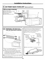
OUTSIDE BACK EXHAUST (Horizontal Duct)
INSTALLATION OVERVIEW
BI. Prepare Rear Wall
B20 Attach Mounting Plate. to Wall
B3. Prepare Top Cabinet
B4. Adjust Blower
BS. Mount the Microwave Oven
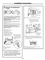
I-_ PREPARING THE REAR WALL
FOR OUTSIDE BACK EXHAUST
[] Place the mounting plate against the rear wall and
align it with the holes drilled earlier.
[] Using a pencil, put dots through holes/notches iv,
G, H and I (see above illustration). Remove the
mounting plate and draw lines extending through
the points. This will give the location and size of the
box cutout for the rear wall duct.
[] Use a saw (saber or keyhole) to cut out the opening.
[] Place the microwave in its upright position with the
top of the unit facing up.
This microwave oven is shipped assembled fbr top
exhaust. You will need the exhaust adaptor fbr
installation in the rear wall opening. To remove the
exhaust adaptor fi'om the micro,a-ave oven:
[] Remove tape securing dampm:
[] Lift off the
[] Remove and, blower plate
save screw \\ and attached
Damper
that holds _ / adaptor from
blower "qate I "/ the microwave.
to mlcro_ave. ,.,..", "-,
_jo_ '_j° I_wlll_l I
..... :-
. _ Back'of
"---. s--"" Microwave
[] Slide exhaust adaptor to one side and remove it.
15

Installation Instructions
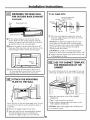
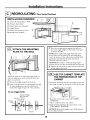
F_ PREPARING THE REAR WALL
FOR OUTSIDE BACK EXHAUST
(continued)
House DamperHingeOnTop
Duct "_..
DamperSwing',
[_Fit the exhaust adaptor into the house duct as
shown. Make sure the exhaust adaptor (with the
damper) is squared up in the house duct and lines
up with the holes in the mounting plate.
[_Remove the paper fi'om the sticky"side of the 28"
foam tape. Press the sticky side onto the face of the
exhaust adaptor: (Don't stretch the foam tape.)
[]Attach the other 28" foam tape to the front of
the mounting plate around both of the exhaust
openings where it will touch the microwave.
I-_ ATTACH THE MOUNTING
PLATE TO THE WALL
Attach the plate to the wall using toggle bolts. At least
one wood screw must be used to at_ch the plate to
a wall stud.
[] Remove the toggle wings fi'om the bolts.
[] lnsert the bolts into the mounting plate through
the holes desi_ nated to go into drywall and
reattach the toggle wings to :_A"onto each bolt.
To use toggle bolts:
SpacingforTogglesMore
_,_ ThanWallThickness
IToggleWings
Mounting IIIli /Togge II II
Plate411:llJ_,SoltII I::t_
-p,'
111:12 ,, ,,
BoltEnd
[]Place the the wall andmounting plate against
insert the toggle wings into the holes in the wall
to mount the plate.
NOTE: Before tightening toggle bolts and wood
screw, make sure the tabs on the mounting plate
touch the bottom of the cabinet when pushed flush
against the wall and that the plate is properly
centered under the cabinet.
CAUTION: Be careful to avoid pinching fingers
between the back of the mounting plate and the ,a-all.
[] Tighten all bolts. Pull the plate away"fi'om the wall
to help tighten the bolts.
I-_ USE TOP CABINET TEMPLATE
FOR PREPARATION OF TOP
CABINET
You need to drill holes for the top support screws and
a hole large enough for the power cord to fit through.
• Read the instructions on the TOP CABINET
TEMP_TE.
• Tape it underneath the top cabinet.
• Drill the holes, following the instructions on the
TOP C&BINET TEMP_TE.
CAUTION: Wear safety goggles when drilling holes
in the cabinet bottom.
16

Installation Instructions
ADAPTING MICROWAVE
BLOWER FOR OUTSIDE
BACK EXHAUST
Remove and save screw that holds blower motor
to microwave.
BlowerMotor
Microwave
- _ BlowerMotor
- _- Screw
[] Careflflly the blower unit. The wires willpull
out
extend far enough to allow you to adjust the
blower unit.
EndB
[] Rotate blower unit counterclockwise 180 °.
BeforeRotation AfterRotation
Microwave Microwave
[] Gently remove the wires from the
grooves.
Reroute the wires through grooves on other side
of the blower unit.
BeforeRerouting After Rerouting
WiresRoutedThroughRightSide WiresRoutedThroughLeftSide
[] Roll the blower unit 90 ° so that fan blade
openings are facing out the back of the
microwave.
BeforeRoiling After Roiling
Backof
Microwave
Microwave
[] Place tim blower unit back into the opening.
CAUTION: Do not pull or stretch the Mower
unit wiring. Make sure the wires are not
pinched,
NOTE: The blower trait exhaust
opem.'ngs should match exhaust
opemngs on rear of microwave oven.
[] Secure the blower unit to the microwave with
the screw from Step 1.
BlowerPlate
I Backof
Microwave
BlowerMotor
, Screw
[] Replace the blower plate in the same position
as before with the screw.
17

Installation Instructions
MOUNT THE MICROWAVE
OVEN
FOR EASIER INSTALLATION AND PERSONAL
SAFEqY, WE RECOMMEND THAT TWO PEOPLE
INSTALL THIS MICROWAVE OVEN.
IMPORTANT: Do not grip or ase handle
dttring installation.
NOTE: If your cabinet is metal, use the nylon
grommet around the power cord hole to prevent
cutting of the cord.
NOTE: We recommend using filler blocks if the
cabinet front hangs below the cabinet bottom shel£
IMPORTANT: If filler blocks are not
used, case damage may occur from over
tightening screws.
NOTE: When mounting
the microw-ave oven,
thread power cord
through hole in bottom of
top cabinet. Keep it tight
throughout Steps 1-3. Do
not pinch cord or lift
oven by pulling
[]Lift microwave, tilt it
tbrward, and hook
slots at back bottom
edge onto four lower
robs of mounting
plate.
\
[_ Rotate fi'ont of
oven
up against cabinet
bottom.
[] Insert a seltXaligning screw through right top center
cabinet hole. Temporarily secure the oven by"
turning the screw at least two full turns after the
threads have engaged. (It will be completely
tightened later.) Be sure to keep power cord tight.
Be careful not to pinch the cord, especially when
mounting flush to bottom of cabinet.
CabinetFront
vA CabinetBottomShelf
_'_A FillerBlock
| _/1_ T Equivalent
/ I ,,"tT//NINIII/t0 ae itnhet
1,.,. Ir,£irl!_ .__(._Recess
--Microwave OvenTop
[]Attach the microwave oven to the top cabinet.
[] Insert 3 seltXaligning screws
through outer top cabinet
holes. Turn two full turns on
each screw.
I
]Tighten right
center screw
completel F
[] Tighten the remaining three screws to the top
of the microwave oven. (While tightening screws,
hold the microwave oven in place against the wall
and the top cabinet.)
t
_ Install grease filters. See the Owner's Manual
packed with the microwave.
18

Installation Instructions
RECIRCULATING (Non-Vented Ductless)
INSTALLATION OVERVIEW
CI. Attach Mounting Plate to Wall
C2. Prepare Top Cabinet
C3. Check Microwave _Msembly
C4. Adjust Blower
C5. Mount the Microwave Oven
C6. Install Charcoal Filmr
I-_ ATTACH THE MOUNTING
PLATE TO THE WALL
1
Attach the plate to the wall using toggle bolts. At
least one wood screw must be used to attach the
plate to a wall smd.
[] Remove the toggle wings fi'om the bolts.
[] Insert the bolts into the mounting plate through
the holes designated to go into &Twall and
reattach the toggle wings to ¾" onto each bolt.
To use toggle bolts:
SpacingforToggles
MoreThanWall
_Thickness
LroggleWings
Mounting II1,11 /To_qle II I'1
Plate_lllh_Bolt II I
III ,t_Wall II U I
BoltEnd
[] Place the mounting plate against the wall and
insert the toggle wings into the holes in the wall
to mount the plate.
NOTE: Betore tightening toggle bolts and wood
screw, make sure the tabs on the mounting plate
touch the bottom of the cabinet when pushed flush
against the wall and that the plate is properly
centered under the cabinet.
CIAUTION: Be careflfl to avoid pinching fingers
between the back of the mounting plate and the wall.
_ Tighten all bolts. Pull the plate away from the wall
to help tighten the bolts.
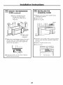
I-_ USE TOP CABINET TEMPLATE
FOR PREPARATION OF TOP
CABINET
You need to drill holes for the top support screws and
a hole large enough for the power cord to fit through.
• Read the instructions on the TOP CABINET
TEMPLATE.
• Tape it underneath the top cabinet.
• Drill the holes, tollowing the instructions on the
TOP CABINET TEMPLATE.
CAUTION: Wear satbg¢ goggles when drilling holes
in the cabinet bottom.
19

Installation Instructions
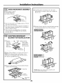
CHECK MICROWAVE ASSEMBLY
Exhaust Adaptor (absent
on models shipped for
recirculation exhaust) \
,,-.wm
.o._ ,ll_° "l"llea_,_m, I
............... ......."7""
Back0,
.J-' CO ' Mlcrewave
• Place the microwave in its upright position, with the
top of the unit facing up.
• The microwave oven may be shipped assembled fbr
top exhaust (adaptor installed) or for recirculation
exhaust (adaptor absent).
• If the micro,a-ave was shipped fbr recirculation
exhaust, skip to C5. If shipped for top exhaust,
proceed with C4.
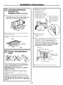
ADAPTING MICROWAVE
BLOWER FOR RECIRCULATION
[] Remove --_ [] Lift offthe
and save 1 blower plate
screw that and attached
holds blower adaptor fl'om
plate to the microwave.
microwave. _"
"" _ Microwave
zz Jj
[] Slide exhaust adaptor to one side and remove it.
NOTE: The exhaust adaptor with damper is not
needed for recirculating models. You may want to
save them for possible future use.
Remove and save the screw that holds the blower
motor to the microwave.
BlowerPlate
"_-_ Screw
Careflllly pull out the blower unit. The wires
will extend fhr enough to allow you to adjust the
blower unit.
[] Roll the blower unit 90 ° so that fan blade openings
are facing to,a-ard the front of the microwave.
B011
NOTE: Make sure ,aires_remain routed in the
grooves of the motor frame.
2O
Page is loading ...
Page is loading ...
Page is loading ...
Page is loading ...
-
 1
1
-
 2
2
-
 3
3
-
 4
4
-
 5
5
-
 6
6
-
 7
7
-
 8
8
-
 9
9
-
 10
10
-
 11
11
-
 12
12
-
 13
13
-
 14
14
-
 15
15
-
 16
16
-
 17
17
-
 18
18
-
 19
19
-
 20
20
-
 21
21
-
 22
22
-
 23
23
-
 24
24


Ask a question and I''ll find the answer in the document
Finding information in a document is now easier with AI
Related papers
-
GE JVM1665 User manual
-
GE JVM2052 User manual
-
GE JVM1665SN2SS Owner's manual
-
GE JNM1541DP1WW Installation guide
-
-
Hotpoint JVM1850BH06 Installation guide
-
Frigidaire PVM1870DM2WW Installation guide
-
GE 1800 Series Installation guide
-
GE 1800 Series Installation guide
-
GE 1800 Series Installation guide
Other documents
-
Amana MMV4205BAQ Installation guide
-
Maytag MMV4205 Installation Instructions Manual
-
Dometic DOTR16B Over Range Microwave Oven Installation guide
-
-
Electrolux Over The Range Microwave Oven User manual
-
Philips BTB2462/05 Quick Setup Guide
-
Frigidaire FMT148GPB1 Installation guide
-
Summit MHOTR243SS Installation guide
-
Frigidaire CFMV157GSA Installation guide
-
Samsung MC17T8000CG Installation guide