Westinghouse R4GD-X Installation guide
- Category
- Stoves
- Type
- Installation guide
This manual is also suitable for

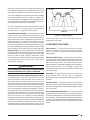
Installation Instructions
Single Package Gas Heating/Electric Cooling
Do not store or use gasoline or other
flammable vapors and liquids in the
vicinity of this or any other appliance.
Do not use this furnace if any part has
been under water. A flood-damaged fur-
nace is extremely dangerous. Attempts
to use the furnace can result in fire or
explosion. A qualified service agency
should be contacted to inspect the fur-
nace and to replace all gas controls,
control system parts, electrical parts
that have been wet or the furnace if
deemed necessary.
DO NOT DESTROY. PLEASE READ CAREFULLY AND KEEP IN A SAFE PLACE FOR FUTURE REFERENCE.
Improper installation,
adjustment, alteration,
service, or maintenance
can cause injury or prop-
erty damage. Refer to
this manual. For assis-
tance or additional in-
formation consult a
qualified installer, ser-
vice agency, or the gas
supplier.
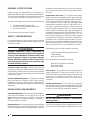
These instructions are primarily intended to assist qualified individuals experienced in the proper installation of this
appliance. Some local codes require licensed installation/service personnel for this type of equipment. Read all
instructions carefully before starting the installation.
FOR YOUR SAFETY
WHAT TO DO
IF YOU SMELL GAS
• Do not try to light any
appliance.
• Do not touch any electri-
cal switch; do not use
any phone in your build-
ing.
• Immediately call your
gas supplier from a
neighbor's phone. Fol-
low the gas supplier's
instructions.
• If you cannot reach your
gas supplier, call the fire
department.
• Extinguish any open
flame.
High Efficiency
FOR YOUR SAFETY
WARNING:
!

2

3
GENERAL SPECIFICATIONS ..................................... 4
SAFETY CONSIDERATIONS...................................... 4
• Literature, Labels, and Tags.................................. 4
• Pressures Within The System .............................. 4
INSTALLATION REQUIREMENTS .............................. 4
• Equipment Application .......................................... 4
• Equipment Check ................................................. 4
• Requirements and Codes...................................... 4
• Unit Location......................................................... 4
• Venting Requirements ........................................... 4
• Unit Dimensions ................................................... 5
• Clearances to Combustible Materials.................... 6
• Thermostat ........................................................... 6
• Air Filter Requirements ......................................... 6
• Condensate Drain ................................................. 7
UNIT INSTALLATION .................................................. 7
• Ground Level ........................................................ 7
• Rigging and Hoisting ............................................. 8
• Rooftop................................................................. 8
AIR SUPPLY FOR COMBUSTION
AND VENTILATION ................................................ 8
CIRCULATING AIR SUPPLY....................................... 9
• Unconditioned Spaces .......................................... 9
• Acoustical Ductwork ............................................. 9
• Airflow Data ........................................................ 10
• Horizontal to Down Flow Conversion ................... 11
GAS SUPPLY AND PIPING ...................................... 11
• Leak Check ........................................................ 11
GAS AND HIGH ALTITUDE CONVERSIONS ............ 11
• High Altitude Application ..................................... 12
• Natural Gas High Altitude Conversion ................. 12
• LP/Propane Gas Conversion............................... 12
ELECTRICAL WIRING............................................... 13
• General ............................................................... 13
• Line Voltage ........................................................ 13
• Electrical Data Table .......................................... 14
LOW VOLTAGE WIRING ........................................... 14
• Heating Configurations........................................ 14
VARIABLE SPEED BLOWER.................................... 17
• Configuring the Blower ........................................ 17
• Selecting Heat Airflow......................................... 17
• Selecting the Cooling Airflow .............................. 17
WIRING DIAGRAMS .................................15-17, 19-20
SYSTEM CHECK ..................................................... 18
• Pre-Start Check List .......................................... 18
START-UP PROCEDURE......................................... 18
• Air Circulation .................................................... 18
• Short Cycle Protection....................................... 21
• System Cooling ................................................. 21
• System Heating ................................................. 21
• Verifying and Adjusting Firing Rate .................... 21
• Verifying and Adjusting Temperature Rise ......... 21
• Lighting/Operating Instructions .......................... 22
• Verifying Burner Operation ................................. 23
• Verifying Operation of Over-Temperature
Limit Control ................................................... 23
COMPONENT FUNCTIONS ..................................... 23
• Flame Sensor .................................................... 23
• Flame Roll-Out Control....................................... 23
• Gas Valve.......................................................... 23
• Pressure Switch ................................................ 23
• Over-Temperature Limit Control ......................... 24
UNIT MAINTENANCE ............................................... 24
• Refrigerant Charging .......................................... 24
• Routine Maintenance ......................................... 25
• Air Filter............................................................. 25
• Vent Cover Assembly........................................ 25
• Condensate Drain and Outdoor Coil ................... 25
• Electrical ........................................................... 25
• Motor Lubrication ............................................... 25
• Blower Compartment ......................................... 25
• Heat Exchanger and Burner Maintenance .......... 25
• Cleaning of Heat Exchanger............................... 25
• Cleaning of Burners ........................................... 26
SEQUENCE OF OPERATION .................................. 26
• Heating Mode .................................................... 26
• Cooling Mode..................................................... 27
• Fan Mode .......................................................... 27
• Unit Fails to Operate.......................................... 27
INSTALLATION CHECKLIST................................... 28
TABLE OF CONTENTS

4
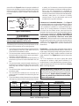
GENERAL SPECIFICATIONS
Single Package Gas Heating/Electric Cooling units are
designed for outdoor rooftop or ground level slab installations.
The units are shipped ready for horizontal duct connections
and are easily converted for down flow connections.
All models are shipped from the factory with the following:
1. Variable speed direct-drive blower.
2. Horizontal or down flow duct connections.
3. 24V fuse protection.
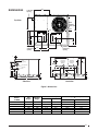
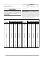
The unit dimensions are shown in Figure 1.
SAFETY CONSIDERATIONS
It is the responsibility of the installer to ensure that the
installation is made in accordance with all applicable local
and national codes.
!
WARNING:
Improper installation, service, adjustment, or
maintenance may cause explosion, fire, electrical
shock or other hazardous conditions which may
result in personal injury or property damage.
Unless otherwise noted in these instructions,
only factory authorized kits or accessories may
be used with this product.
Literature, Labels, and Tags — When working with this
equipment, follow all precautions in the literature, on tags,
and on labels provided with the unit and/or approved field
installed kits. The type of hazard and severity are described
on each label or tag.
Pressures Within The System — This equipment contains
liquid and gaseous refrigerant under high pressure.
Installation or servicing should only be performed by
qualified trained personnel thoroughly familiar with this type
equipment.
INSTALLATION REQUIREMENTS
Equipment Application — Before beginning the installation,
verify that the unit model is correct for the job. The unit
model number is printed on the data label. This furnace is
NOT to be used for temporary heating of buildings or
structures under construction.
Equipment Check — All units have been securely packaged
at the point of shipment. After unpacking the unit, carefully
inspect it for apparent and concealed damage. Claims for
damage should be filed with the carrier by the consignee.
Also check that there are no obvious signs of deterioration
of the unit.
Requirements and Codes — The installer must comply
with all local codes and regulations which govern this type
of equipment. Local codes and regulations take precedence
over any recommendations contained in these instructions.
In the absence of local codes, the installation must
conform with the National Fuel Gas Code (ANSI 2223.1,
NFPA-54), or Canadian installations must conform with
CAN/CGA-B149 installation codes. All electrical wiring
must be made in accordance with codes and regulations
and with the National Electric Code (ANSI/NFPA 70) or in
Canada the Canadian Electric Code Part 1 CSA C.22.1. Air
Ducts must be installed in accordance with the standards
of the National Fire Protection Association “Standards for
Installation of Air Conditioning and Ventilation Systems”
(NFPA 90A), “Standard for Installation of Residence Type
Warm Air Heating and Air Conditioning Systems” (NFPA
90B), these instructions, and all applicable local codes.
The National Fuel Gas Code is available by writing:
American National Standards Institute, Inc.
1430 Broadway
New York, NY 10018
NFPA publications are available by writing:
National Fire Protection Association
Batterymarch Park
Quincy, ME 02269
Unit Location — The gas/electric unit is designed only for
outdoor installations. Choosing the location of the unit
should be based on minimizing the length of the supply and
return ducts. Consideration should also be given to
availability of fuel, electric power, service access, noise,
and shade.
Venting Requirements — This unit has been equipped
with an integral venting system and designed to operate
only with this venting system. No additional venting shall
be used. This unit must be vented to the outdoors.
!
WARNING:
Do not vent furnace through a conventional
venting system.
A vent cover assembly has been supplied with the unit. It
can be found secured to the gas controls within the control

5
Back ViewSide View
24.9
13.5
16.0
23.5
12.0
13.3
45.7
13.5
16.0
12.0
CG
B
A
47.5
Downflow
Return Duct
Opening
Downflow
Supply Duct
Opening
Inside
Perimeter
of Base Rail
2.63"
To Electrical
Opening
DIMENSIONS
Figure 1. Dimensions
Top View
47.5
Electric
Supply Entry
Low Voltage Entry
Gas Supply
Entry
16.6
24.6
31.0
2.9
1.8
4.0
12.45
12.45
4.0
55.8
8.75
Horizontal
Supply Duct
Opening
Horizontal
Return Duct
Opening
4.0
1.75
9.75 24.75
16.0
Condensing
Coil
13.5
13.5
16.0
16.0
C
29.75
23.75
15.75
4.0
Model Center of Gravit
y
Height (in inches)
Number C
13 SEER with base rails without base rails
X24K072X
410 420 25.5 27.0 35.0 31.3
X30K072X
430 440 26.0 26.5 39.0 35.3
X36K100X
480 490 26.0 27.0 39.0 35.3
X42K100X
480 490 27.0 26.5 39.0 35.3
X48K120X
530 540 27.0 26.5 43.0 39.3
X60K120X
530 540 27.0 26.5 43.0 39.3
AB
Unit
Weight
Shipping
Weight

6
Nominal Approximate Approximate Recommended
Cooling Air Flow Range Filter Area (Sq. In.)* Filter Size (In. x In.)
Tonnage (Ton) (CFM) Disposable High Velocity Disposable High Velocity
2.0 700-900 450 275 20 x 25 15 x 20
2.5 800-1100 550 325 20 x 30 16 x 20
3.0 1000-1300 625 375 25 x 25 20 x 20
3.5 1200-1500 725 450 24 x 30 20 x 25
4.0 1300-1700 825 500 18 x 24 (2 required) 20 x 25
5.0 1700-2100 1000 600 20 x 25 (2 required) 25 x 25
*Based on velocity of 300 ft/min for disposable filters and 500 ft/min for high velocity (cleanable) filters.
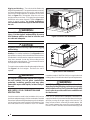
area of this unit. Figure 2 shows the proper installation of
the vent cover assembly over the vent outlet on the exterior
of the corner panel. The fasteners used to secure the vent
cover assembly have been included in the homeowner's
package.
!
WARNING:
The vent cover assembly must be installed to
assure proper operation of the unit.
The following list is a summary of the requirements for the
location of the termination of the venting system:
1. The location of the vent termination must be consistent
with the National Fuel Gas Code (ANSI Z223.1) or
CAN/CGA-B149 Installation Codes.
2. The vent termination must be located at least four (4)
feet horizontally from any electric meters, gas meters,
regulators, and relief equipment.
3. The vent termination must be located at least three (3)
feet above any forced air inlet located within ten (10)
feet.
4. The vent termination must be located at least four (4)
feet below, four (4) feet horizontally from, or one (1) foot
above any door, window, or gravity air inlet into any
building.
5. The vent termination must be located at least one (1)
foot above grade.
6. The unit should be installed in such a manner as to
prevent snow accumulation from obstructing the vent
termination.
7. The unit installation shall avoid areas where condensate
drainage may cause problems by dropping on planters
Table 1. Air Filter Requirements
IMPORTANT NOTICE TO INSTALLER: After installing
or replacing the filtration system for this unit, add the
following marking on the filter service panel or reasonably
adjacent thereto: “Replace filter(s) installed in your
system only with the same dimensional size filters
that are being replaced.”
or patios, etc. Furthermore, ensure that the exhaust
gases will not impinge on windows or building surfaces,
which may be compromised or damaged by
condensation. Do not install the unit such that exhaust
from the vent termination is directed into window wells,
stairwells, under decks, or in alcoves or similarly
recessed areas. The vent termination must not be
located above any public walkways.
Clearances to Combustible Materials — See Figure 3
for required clearances to combustible materials. Refer to
the unit data label for the model number. The gas/electric
unit is suitable for installation on combustible flooring or
class A, B, or C roofing materials. A clearance of at least
36 inches from the blower access panel and from the
louvered control access panel is recommended to allow for
servicing and maintenance. Where accessibility to
combustibles clearances are greater than minimum
clearances, accessibility clearances must take
preference. Sufficient clearance for unobstructed airflow
through the louvered control access panel and through the
outdoor coil must be maintained in order to achieve rated
performance. See Figure 3 for minimum clearances to
obstructions.
Thermostat — A single stage cooling/two stage heating
24VAC thermostat should be used with the 2-4 ton units. A
single stage cooling/single-stage heating thermostat can
be used for single stage, outdoor ambient or timed two
stage operation. See Figure 8a-e for typical thermostat
wiring.
The 5-Ton Gas/Electric unit uses a special two speed
compressor to achieve a high level of efficiency in a
compact frame. For the highest efficiency the use of a two-
stage cooling thermostat is recommended. Refer to Figure
9b for unit wiring diagram.
Figure 2. Vent Assembly
Corner Panel
of Unit
Vent Cover
Assembly
Fastener
Exhaust Duct
Opening

7
36"
36"
1"*
36"
36"
Figure 3. Minimum Clearances to combustible materials.
Air Filter Requirements — A suitable air filter system
must be installed in the unit or in the return air system
upstream of the evaporator coil. Refer to Table 1 for
recommended filter sizes. Air filter pressure drop must not
exceed 0.08 inches WC. This unit is not supplied with air
!
WARNING:
Never operate unit without a filter. A failure to
follow this warning could result in a fire, personal
injury, or death.
filter(s) and has no factory equipped means for
accommodating internal air filter(s). For downflow
installations only, an internal filter accessory kit can be
ordered. For horizontal installations, the air filter system
must be installed in the return air ductwork. All return air
to this unit must pass through the filter(s) before entering
the evaporator coil.
Condensate Drain — Condensate is removed from the
unit through the 3/4" female pipe fitting located on the front
side of the unit. (See Figure 4.) Install a 2 inch deep
condensate trap in the drain line of the same size and prime
with water.
When connecting rigid drain line, hold the female fitting with
a wrench to prevent twisting. Do not over tighten! Refer
to local codes and restrictions for proper condensate
disposal requirements.
UNIT INSTALLATION
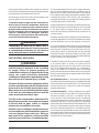
Ground Level — When installing the unit at ground level
(See Figure 5), provide a concrete mounting pad separate
from the building foundation. The pad must be level to
insure proper condensate disposal and strong enough to
support the unit’s weight (Refer to Figure 1). Make sure the
slab is a minimum of 2" above the grade and in an area that
drains well.
Figure 4. Condensate Drain.
Condensate Drain
* If accessories are installed, see Accessory Installation Instructions for proper clearances.

8
2"
Figure 5. Ground Level Installation.
Rigging and Hoisting — The unit should be lifted using
slings and spreader bars. The spreader bars are necessary
to prevent damaging the top of the unit’s cabinet. Make
sure that the lifting equipment is adequate for the load.
Refer to Figure 1 for unit weights. Keep the unit in an
upright position at all times. The rigging must be located
outside the unit’s center of gravity. Refer to Figure 1 for
center of gravity location. For rooftop installations,
remove and discard the two supports attached beneath
the unit.
!
WARNING:
To avoid the risk of property damage or personal
injury, it is the rigger’s responsibility to ensure
that whatever means are used to hoist the unit
are safe and adequate.
!
CAUTION:
All panels must be securely in place when rigging
and hoisting.
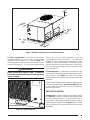
Rooftop — For rooftop installations (See Figure 6) use the
appropriate accessory roof curb and follow all instructions
included with it. Make sure the supports beneath the unit
have been removed. Locate the unit according to local
building codes and ordinances. The curb must be level to
insure proper condensate drainage.
The roof must be capable of handling the weight of the unit.
See Figure 1 for unit weights. Reinforce the roof if
required.
!
WARNING:
Do not place combustible material on or against
the unit cabinet. Do not place combustible
materials, including gasoline and any other
flammable vapors and liquids, in the vicinity of
the unit.
AIR SUPPLY FOR COMBUSTION AND
VENTILATION
Provisions must be made in the installation of this unit to
provide an adequate supply of air for combustion. Detailed
instructions for determining the adequacy of an installation
can be found in the current revision of the National Fuel
Gas Code (ANSI Z223.1) and NFPA 54, or in Canadian
installation codes (CAN/CGA-B149), or in applicable local
building codes. Consult local codes for special requirements.
!
WARNING:
Installation using methods other than those
described in the following sections must comply
with the National Fuel Gas Code and all applicable
local codes to provide sufficient combustion air
for the furnace.
If the unit is operated with inadequate combustion air
supply the flame roll-out control located above the burners
will open, turning off the gas supply to the burners. The
flame roll-out control is a manually re-setable device. DO
NOT install a jumper wire across this control to defeat its
function. DO NOT reset the control without identifying and
Figure 6. Roof Curb Installation.

9
correcting the fault condition which caused the control to
trip. If this control must be replaced, use only the replacement
part specified in the Replacement Parts List.
Air Openings in the door of the unit, warm air registers, and
return air grilles must not be restricted.
To maximize heat exchanger life, the combustion air
must be free of chemical contaminants which form
corrosive acidic compounds when combusted. Some
examples of these chemical contaminants are chlorine,
fluorine, and sulphur. Some common sources of these
chemical contaminants are detergents, bleaches,
aerosol sprays, cleaning solvents, and a wide variety
of commercial and household products.
!
WARNING:
Combustible air must not be drawn from a
contaminated atmosphere. Excessive exposure
to contaminated combustion air will result in
safety and performance related problems.
CIRCULATING AIR SUPPLY
!
WARNING:
Products of combustion must not be allowed to
enter the return air ductwork or the circulating
air supply. Failure to prevent products of
combustion from being circulated into the living
space can create potentially hazardous
conditions including carbon monoxide poisoning
that could result in personal injury or death.
All return ductwork must be adequately sealed,
all joints must be taped, and the ductwork must
be secured to the unit with sheet metal screws.
When return air is provided through the bottom
of the unit, the joint between the unit and the
return air plenum must be air tight.
The roof curb or cement pad on which the unit is
mounted must provide sound physical support
of the unit with no gaps, cracks, or sagging
between the unit and the curb or pad.
Return air and circulating air ductwork must not
be connected to any other heat producing device
such as a fireplace insert, stove, etc. Doing so
may result in fire, explosion, carbon monoxide
poisoning, personal injury, or property damage.
This unit is designed only for use with a supply and return
duct. Air ducts should be installed in accordance with all
applicable local codes and the standards of the National
Fire Protection Association “Standard for Installation of Air
Conditioning Systems” (NFPA 90A), and “Standard for
Installation of Residence Type Warm Air Heating and Air
Conditioning Systems” (NFPA 90B).
Design the ductwork according to methods described by
the Air Conditioning Contractors of America (ACCA) Manual
D. The ducts must be properly sized not to exceed 0.2
inches WC pressure drop at 400 scfm per nominal ton of
cooling capacity.
Ductwork should be attached directly to the unit flanges for
horizontal applications. On roof curb installations the ducts
must be attached to the curb duct supports, not the unit.
It is recommended that the outlet duct be provided with a
removable access panel. This opening should be accessible
when the unit is installed in service and shall be of a size
such that the smoke or reflected light may be observed
inside the casing to indicate the presence of leaks in the
heat exchanger. The cover for the opening shall be attached
in such a manner as to prevent leaks.
If outside air is utilized as return air to the unit for ventilation
or to improve indoor air quality, the system must be
designed so that the return air to the unit is not less than
50°F (10°C) during heating operation. If a combination of
indoor and outdoor air is used, the ducts and damper
system must be designed so that the return air supply to the
furnace is equal to the return air supply under normal, indoor
return air applications.
Unconditioned Spaces — All ductwork passing through
unconditioned space must be properly insulated to minimize
duct losses and prevent condensation. Use insulation with
an outer vapor barrier. Refer to local codes for insulation
material requirements.
Acoustical Ductwork — Certain installations may require
the use of acoustical lining inside the supply ductwork.
Acoustical insulation must be in accordance with the
current revision of the Sheet Metal and Air Conditioning
Contractors National Association (SMACNA) application
standard for duct liners. Duct lining must be UL classified
batts or blankets with a fire hazard classification of FHC-25/
50 or less. Fiber ductwork may be used in place of internal
duct liners if the fiber ductwork is in accordance with the
current revision of the SMACNA construction standard on
fibrous glass ducts. Fibrous ductwork and internal acoustical
lining must be NFPA Class 1 air ducts when tested per UL
Standard 181 for Class 1 ducts.

10
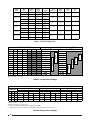
Table 3. 13 SEER Airflow Data.
NOTE: 0 = OFF 1 = ON
Table 4a. Cooling Airflow Settings
NOTE: 0 = OFF 1 = ON
# Switch is not used — Can be 0 or 1
1. Recommended temperature rises are highlighted in bold.
2. Temperature rises in the table are approximate. Actual temperature rises may vary.
Table 4b. Heating Airflow Settings
High Fire Input High Fire Input High Fire Input
567
00# N/A N/A N/A N/A 900 51 1500 51 900 61 1500 61
10# N/A N/A N/A N/A 1100 42 1585 48 1100 50 1585 58
01# 750 49 1000 55 1100 42 1805 42 1100 50 1805 51
11# 990 37 1200 46 1200 38 2005 38 1200 46 2005 46
48,000 72,000
Low Fire Input
Switches
Nominal Airflow Rates (CFM) and Temperature Rises (ºF)
120,000
R4GD-*072X R4GD-*100X R4GD-*120X
Low Fire Input
60,000 100,000
Low Fire Input
72,000
Model Heatin
g
Heatin
g
Heat Heatin
g
Coolin
g
Number In
p
ut Out
p
ut Switch Rise Out
p
ut Blower Motor
R4GD (Btuh) (Btuh) Setting
CFM
R
ange
(
°
F)
(Btuh) Size HP
1,1 1200
0,1 1000
1,1 990
0,1 750
1,1 1200
0,1 1000
1,1 990
0,1 750
1,0 1585
0,0 1500
1,0 1100
0,0 900
1,0 1585
0,0 1500
1,0 1100
0,0 900
1,1 2005
0,1 1805
1,1 1200
0,1 1100
1,1 2005
0,1 1805
1,1 1200
0,1 110
0
40-70 56,000 11 X 10 1 X60K120X
120,000
72,000
94,000
56,000
40-70 45,000 11 X 10 1 X48K120X
120,000
72,000
94,000
56,000
40-70 40,000 11 X 10 1
78,000
47,000
X42K100X
100,000
60,000
78,000
47,000
29,000 10 X 10 1/2
X36K100X 40-70 35,000 11 X 10 1
100,000
60,000
X24K072X 35-65
X24K072X 35-65
72,000
48,000
56,000
37,500
72,000
48,000
56,000
37,500
10 X 10 1/224,000
1234567
0001 675 900
1001 720 1000
0000 750 1100
1000 800 1215
0010 825 1350
1010 880 1485
0101 945 1530
1101 990 1700
0100 1050 1870
1100 1100 1890
0110 1155 2100
1110 1210 2310
SWITCH NUMBER Recommended A/C Airflow Rate (CFM)
2 - 2.5 TON 3 - 5 TON
5 Ton
4 Ton
3.5 Ton
3 Ton
2.5 Ton
2 Ton

11
Figure 7. Typical Right Side Entry
Gas Service Connection.
Ground Joint
Union
Dripleg
Shut-Off Valve
with
1
/8 NPT
plugged tap
Burner
Assembly
Manifold
Some utilities
require Shut-Off
Valve to be
4 to 5 feet
above floor
Automatic Gas
Valve (with manual
shut-off)
Horizontal to Down flow Conversion — The unit is
shipped ready for horizontal duct connections. If down
flow ducts are required, the unit must be converted
following the steps below for both the supply and return
ducts.
1. Remove the duct covers from the horizontal flow duct
openings.
2. Locate the duct cap inside the duct openings and
remove the screw holding it in place.
3. Lift the cap out of the unit. The cap can be pushed up
from the bottom by reaching through the fork slot.
4. Reinstall the covers over the horizontal duct opening.
5. Fasten the cover with screws and seal to prevent air
leakage.
GAS SUPPLY AND PIPING
This unit has right side gas entry. A typical gas service
hookup is shown in Figure 7. When making the gas
connection, provide clearance between the gas supply line
and the entry hole in the unit’s casing to avoid unwanted
noise and/or damage to the unit.
All gas piping must be installed in compliance with local
codes and utility regulations. Some local regulations
require the installation of a manual main shut-off valve and
ground joint union external to the unit. The shut-off valve
should be readily accessible for service and/or emergency
use. Consult the local utility or gas supplier for additional
requirements regarding placement of the manual main gas
shut-off. In the absence of local codes the gas line
installation must comply with the latest edition of the
National Fuel Gas Code ANSI Z223.1 or CAN/CGA B149
Installation Codes.
!
CAUTION:
Do not use matches, lighters, candles or other
sources of open flame to check for gas leaks.
A 1/8 inch NPT plugged tap must be installed in the gas line
immediately upstream of the gas supply connection to the
furnace for use when measuring the gas supply pressure.
The plug should be readily accessible for service use. A
drip leg should be installed in the pipe run to the unit. Table
5 lists gas flow capacities for standard pipe sizes as a
function of length in typical applications based on nominal
pressure drop in the line.
IMPORTANT NOTES:
1. Gas piping must not be run in or through air ducts,
chimneys, gas vents, elevator shafts, etc.
2. Compounds used on threaded joints of gas piping must
be resistant to the actions of liquefied petroleum
gases.
3. The main manual gas valve and main power disconnect
to the furnace must be properly labeled by the installer
in case emergency shutdown is required.
Leak Check — After the gas piping to the unit is complete,
all connections must be tested for gas leaks. To check for
leaks in gas piping systems, use only a soap and water
solution or other approved method.
IMPORTANT NOTE: When pressure testing the gas
supply lines at pressures greater than 1/2 psig (14
inches WC), the unit must be disconnected from the
gas supply piping system to prevent damage to the gas
control valve.
If the test pressure is less than or equal to 1/2 psig (14
inches WC), the unit must be isolated from the gas
supply line by closing the manual shut-off valve.
!
WARNING:
This unit was equipped at the factory for use with
natural gas only. A special kit, supplied by the
manufacturer, is required to convert the unit to
operate on LP/propane gas. Failure to use the
proper conversion kit can cause fire, explosion,
property damage, carbon monoxide poisoning,
personal injury, or death.
GAS AND HIGH ALTITUDE CONVERSIONS
Conversion: conversion of this unit must be performed by
qualified service personnel, using only approved parts.

12
High Altitude Application
High altitude application with this furnace can be field
performed by a simple adjustment of manifold pressure
and if necessary, a change of the orifices. The changes
required depend on the installation altitude and the heating
value of the gas. The gas heating value based on sea level
can be obtained from your local gas utility. The heating
value of gas at high altitude is always lower than the sea
level heating value. The heating values used in the Tables
6 & 7 are based on sea level values.
Natural Gas High Altitude Conversion
All factory shipped furnaces are ready to operate between
zero and 4999 ft. above sea level. For higher altitudes
(between 5000 and 10,000 ft. above sea level), conversion
can be achieved simply by adjusting the furnace manifold
pressure as shown in Table 6.
LP/Propane Gas Conversion
IMPORTANT NOTE: When converting a low NOx
Furnace from Natural gas to LP/Propane gas, it is
necessary to remove the NOx Baffles.
Conversion of this furnace to utilize LP/Propane gas must
be made by qualified service personnel, using approved
parts. Conversion for the LP/Propane gas can be
accomplished by adjusting the manifold pressure, after
replacing the natural gas orifices with the appropriate LP/
Propane orifices shown in Table 7. Note: that for
installations between zero and 5000 ft. above sea level, a
#54 drill size orifice should be used. However for
installations above 5000 ft. over sea level, a # 55 drill size
orifice should be used. Then use Table 7 to determine the
appropriate manifold pressure for your altitude installation.
Conversion to LP/Propane (sea level and high altitude ) is
detailed in the installation instructions provided with the
conversion kit. Approved conversion kits are:
United States LP/Propane Gas Sea Level and High Altitude
Conversion Kit - P/N 903616
This kit is for LP/propane conversion in the United States
at altitudes between zero and 10,000 ft. above sea level.
Follow the installation instructions supplied with the kit for
proper installation.
Canadian LP/Propane Gas Sea Level and High Altitude
Conversion Kit - P/N 903617
This kit is for LP/propane conversions in Canada at
altitudes between zero and 4500 ft. above sea level. Follow
the installation instructions supplied with the kit for proper
installation.
!
WARNING:
To avoid the risk of electrical shock, personal
injury, or death, disconnect all electrical power
to the unit before performing any maintenance
or service. The unit may have more than one
electrical power supply. When servicing controls,
label all wires prior to disconnecting and
reconnect wires correctly. Verify proper
operations after any servicing.
!
WARNING:
The unit cabinet must have an uninterrupted or
unbroken electrical ground to minimize personal
injury if an electrical fault should occur. This
ground may consist of electrical wire or approved
conduit when installed in accordance with
existing national or local codes.
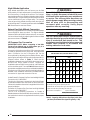
Table 5. Capacity of Black Iron Gas Pipe (cubic feet
per hour) for Natural Gas (specific gravity = .60).
NOMINAL LENGTH OF PIPE RUN
BLACK IRON (feet)
PIPE DIAMETER
(in.) 1020304050607080
1
/
2 130 90 75 65 55 50 45 40
3/4 280 190 150 130 115 105 95 90
1 520 350 285 245 215 195 180 170
1 1/4 1050 730 590 500 440 400 370 350
1 1
/
2 1600 1100 890 760 670 610 560 530
The cubic feet per hour listed in the table above must be greater than the
cubic feet per hour of gas flow required by the unit.
To determine the cubic feet per hour of gas flow required by the unit, divide
the input rate of the unit by the heating value of the gas:
Cubic Feet Per Hour Required
=
Input To Unit (Btu/hr)
Heating Value of Gas (Btu/Cu. Ft.)
CAPACITY OF BLACK IRON GAS PIPE (CU. FT. PER HOUR)
FOR NATURAL GAS (SPECIFIC GRAVITY - 0.60)

13
Table 7. Manifold Pressure (in WC) for LP/Propane Gas at Various Altitudes
Elevation, (feet above sea level)
0 to 2,000 to 5,000 to 6,000 to 8,000 to
1,999 4,999 5,999 7,999 10,000
10.0 8.5 10.0 9.0 8.5
Orifice Size
54 54 55 55 55
Manifold Pressure in (WC)
Based on Sea Level LP
Heatin
g
Value of 2,500 Btu/ft.
3
Table 6. Manifold Pressure (in WC) for Natural Gas at Various Altitudes and Heating Values
For a Natural Gas Sea Level Heating Value of 800 to 899 Btu/cu.ft.
Elevation (feet above sea level)
zero to
1999
2000 to
4999
5000 to
5999
6000 to
7999
8000 to
10000
Manifold Pressure Setting (in WC)
3.5 3.5 3.5
3.5 3.0
For a Natural Gas Sea Level Heating Value of 900 to 999 Btu/cu.ft.
Elevation (feet above sea level)
zero to
1999
2000 to
4999
5000 to
5999
6000 to
7999
8000 to
10000
Manifold Pressure Setting (in WC)
3.5 3.5 3.5
3.2 2.8
For a Natural Gas Sea Level Heating Value of 1,000 to 1,100 Btu/cu.ft.
Elevation (feet above sea level)
zero to
1999
2000 to
4999
5000 to
5999
6000 to
7999
8000 to
10000
Manifold Pressure Setting (in WC)
3.5 3.5
3.0 2.8 2.5
ELECTRICAL WIRING
General — Electrical power wiring must be made in
accordance with all applicable local codes and ordinances,
and with the current revision of the National Electric Code
NFPA 70 or in Canada CSA C.22.1 Canadian Electrical
Code Part 1. If any of the original wire as supplied with the
unit must be replaced, it must be replaced with material of
the same gauge and temperature rating.
Line Voltage — Before proceeding with the electrical
connections, make certain that the voltage, frequency and
phase of the supply source are the same as those specified
on the unit rating plate. Also verify that the service provided
by the utility is sufficient to handle the additional load
imposed by this equipment.
This unit must be electrically grounded in accordance with
local codes or, in the absence of local codes, with the
National Electrical Code (ANSI/NFPA 70) or the CSA
C22.1 Electrical Code.
See Figure 9a-b or the unit wiring label for proper high and
low voltage wiring. Make all electrical connections in
accordance with all applicable codes and ordinances.
Use a separate branch electrical circuit for this unit. A
means of electrical disconnect must be located within sight
of and readily accessibility to the unit.
The unit is shipped from the factory wired for 240 volt
transformer operation. For 208 volt operation, remove the
lead from the transformer terminal marked 240V and
connect it to the terminal marked 208V. For maximum
circuit ampacity and maximum over current protection, see
the unit rating plate or Table 8.
Overcurrent protection must be provided at the branch
circuit distribution panel and sized as shown in Table 8 or
on the unit rating label and according to the National
Electric Code and applicable local codes.
Provide power supply (or supplies) for the unit in accordance
with the unit wiring diagram, and the unit rating plate.
Connect the line-voltage leads to the corresponding

14
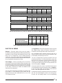
Table 8. Electrical Data.
Notes: FLA = Full Load Amps; LRA = Lock Rotor amps; RLA = Rated Load Amps.
terminals on the contactor inside the control compartment.
Use only copper wire for the line voltage power supply to
this unit. Use proper code agency listed conduit and a
conduit connector for connecting the supply wires to the
unit and for obtaining proper grounding. Grounding may
also be accomplished by using the grounding lug provided
in the control box. Do not use gas piping as an electrical
ground.
LOW VOLTAGE WIRING
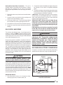
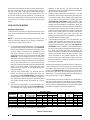
Heating Configurations
These furnaces are factory configured to operate on high
fire only, but can be field converted to operate as two-stage
furnaces.
NOTE: TO achieve full rated capacity and efficiency, the
furnace should be operated in the factory configuration
(high fire only as described in part 2.)
1.
Two stage thermostat configuration
– For this installa-
tion a two stage heating thermostat is used. CAUTION:
Disconnect yellow/black wire from primary gas valve.
Remove female connector from yellow/black wire
and strip insulation from end. Connect stripped
yellow/black wire to (W2) from the thermostat. (See
Figure 8a). The first stage bulb (W1) is connected to
W on the furnace control board. On a call for first stage
heat, the furnace will operate at low fire and the blower
will run at a lower speed. On a call for second stage
heat, the furnace will operate at high fire and the blower
will run at a higher speed. The furnace will stage
between low fire, high fire, and off depending on the
thermostat signal.
2.
High fire only configuration
– As shipped from the
factory, the primary and secondary gas valves are
connected in parallel (See Figure 8b). This defeats the
staging feature and the furnace operates on high fire
only. All of the burners will operate on a call for heat and
the variable speed blower will operate at a higher
speed.
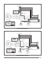
3.
Low fire only configuration
– For this installation, the
secondary gas valve is disconnected (See Figure 8c).
This defeats the staging feature and the furnace
operates on low fire only. The low fire burners will
operate on a call for heat and the variable speed blower
will operate at a lower speed.
4.
Outdoor ambient dependent configuration
– For this
installation, the primary and secondary gas valves are
connected in parallel with an outdoor thermostat (open
on rise style) in series with the secondary gas valve
(See Figure 8d). CAUTION: DO NOT CONNECT W2
from thermostat to the furnace wiring when using the
outdoor ambient dependent configuration. When the
outdoor temperature is above the set point, the outdoor
thermostat opens keeping the secondary gas valve
closed. The furnace operates in the low fire mode at a
lower blower speed. When the outdoor thermostat
closes, the secondary gas valve opens with the
primary gas valve and the furnace operates in the high
fire mode at higher blower speed.
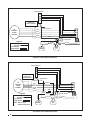
5.
Timed staging configuration
– For this installation, the
primary and secondary gas valves are connected in
parallel with a delay on make timer (two wire style) in
series with the secondary gas valve (See Figure 8e).
CAUTION: DO NOT CONNECT W2 from thermostat to
the furnace wiring when using timed staged configura-
tion. When the primary gas valve is energized, the
furnace operates in the low fire mode at a lower blower
speed and the timer begins its delay function. If the
room thermostat is not satisfied before the timer
activates, the furnace will stage to high fire and the
blower will operate at a higher speed until the room
thermostat is satisfied.
Install the thermostat per the manufacturer's instructions.
The low voltage (24 volt) connections from the thermostat
are made at the terminal strip on the control board in the
furnace. See Figures 8a-8e for the proper connections for
heating only (four wire) and heating/cooling (five wire)
applications. The recommended minimum wire gauge for
thermostat wiring is shown in Table 10.
The thermostat must not be installed on an outside wall or
any other location where its operation may be adversely
affected. Adverse affects include radiant loading from fire-
places, sunlight, or lighting fixtures, and convective loading
from warm air registers or electrical appliances.
Min Max RLA LRA MCA MOP
R4GD-X24K072X
72,000 208-230/30/1 187 253 12.1 54 1.2 4.3 20.6 30
R4GD-X30K072X
72,000 208-230/30/1 187 253 13.6 67 1.2 4.3 22.5 35
R4GD-X36K100X
100,000 208-230/30/1 187 253 16.4 83 1.2 9.1 30.8 45
R4GD-X42K100X
100,000 208-230/30/1 187 253 17.9 88 1.2 9.1 32.7 50
R4GD-X48K120X
120,000 208-230/30/1 187 253 20.4 109 1.2 9.1 35.8 50
R4GD-X60K120X
120,000 208-230/30/1 187 253 28.0 169 1.5 9.1 45.6 70
ELECTRICAL DATA
Compressor
Fan Motor
FLA
Indoor Blower
FLA
Single Circuit
Model Number
Max. Heating
Input
Nominal
Electrical Supply
Voltage Range

15
Figure 8a. Two Stage Configuration
Figure 8b. High Fire Only Configuration
Legend
Field Wiring
Factory Wiring:
Low Voltage
High Voltage
PRIMARY
GAS
VALVE
ROOM THERMOSTAT
R
Y
G
W
SECONDARY
SOLENOID
GAS VALVE
YELLOW/BLACK
TO
VARIABLE
SPEED
BLOWER
CLOSED END
CONNECTOR
DO NOT REMOVE!
BROWN
RED
GREY
YELLOW
GREEN
YELLOW
BROWN
BROWN
YELLOW
FLAME SENSOR
R
BROWN
BROWN
YELLOW
BROWN
FLAME SENSOR
R
Legend
Field Wiring
Factory Wiring:
Low Voltage
High Voltage
PRIMARY
GAS
VALVE
TWO STAGE
ROOM THERMOSTAT
R
Y
G
W
SECONDARY
SOLENOID
GAS VALVE
TO
VARIABLE
SPEED
BLOWER
W2
YELLOW/BLACK
CLOSED END
CONNECTOR
DO NOT REMOVE!
BROWN
RED
GREY
YELLOW
GREEN
YELLOW
BROWN
YELLOW
BROWN
BROWN
YELLOW
YELLOW
BROWN
BROWN

16
Figure 8c. Low Fire Only Configuration
Legend
Field Wiring
Factory Wiring:
Low Voltage
High Voltage
PRIMARY
GAS
VALVE
ROOM THERMOSTAT
R
Y
G
W
SECONDARY
SOLENOID
GAS VALVE
TO
VARIABLE
SPEED
BLOWER
YELLOW/BLACK
CLOSED END
CONNECTOR
DO NOT REMOVE!
BROWN
RED
GREY
YELLOW
GREEN
YELLOW
BROWN
YELLOW
BROWN
BROWN
FLAME SENSOR
R
BROWN
YELLOW
BROWN
YELLOW
YELLOW
Figure 8d. Outdoor Ambient Dependent
PRIMARY
GAS
VALVE
ROOM THERMOSTAT
R
Y
G
W
TO
VARIABLE
SPEED
BLOWER
SECONDARY
SOLENOID
GAS VALVE
CLOSED END
CONNECTOR
DO NOT REMOVE!
ODT
Legend
Field Wiring
Factory Wiring:
Low Voltage
High Voltage
ODT: Open on rise
outdoor thermostat
YELLOW/BLACK
VSB
W
BROWN
RED
GREY
YELLOW
GREEN
YELLOW
BROWN
YELLOW
YELLOW
BROWN
BROWN
BROWN
FLAME SENSOR
R
BROWN
YELLOW
YELLOW
BROWN

17
Figure 8e. Timed Two Stage Configuration
PRIMARY
GAS
VALVE
ROOM THERMOSTAT
R
Y
G
W
SECONDARY
SOLENOID
GAS VALVE
SDT
Legend
Field Wiring
Factory Wiring:
Low Voltage
High Voltage
CLOSED END
CONNECTOR
DO NOT REMOVE!
SDT: Two wire delay on
make timer
TO
VARIABLE
SPEED
BLOWER
YELLOW/BLACK
VSB
W
BROWN
RED
YELLOW
GREEN
YELLOW
GREY
BROWN
BROWN
BROWN
YELLOW
YELLOW
BROWN
FLAME SENSOR
R
BROWN
YELLOW
YELLOW
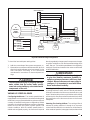
To check the heat anticipator setting either:
1. Add the current draw of the system components; or
2. Measure the current flow on the thermostat R-W circuit
after the circulating blower motor has started. Set the
heat anticipator according to the thermostat
manufacturer's instructions for heat anticipator set-
tings.
!
CAUTION:
To avoid personal injury or property damage,
make certain that the motor leads cannot
come into contact with any uninsulated metal
components of the unit.
VARIABLE SPEED BLOWER
Configuring the Blower—The variable speed blower is
equipped with a microprocessor-controlled variable speed
motor that is pre-programmed to deliver optimum airflow in
a variety of conditions and system configurations. Before
operation, the variable speed blower must be configured to
match the unit with the system, system options, and
climatic conditions. With the variable speed blower in-
stalled and configured properly, the furnace will respond
directly to gradually change speed in response to changes
in system variables such as the thermostat settings, duct
static, filter, etc. The variable speed blower is configured by
setting the 6 switches located on the motor control board
as described below.
!
IMPORTANT:
The variable speed blower has been designed
to give the installer maximum flexibility to
optimize system performance, efficiency, and
comfort. Because there are so many ways to
configure, it is important to read and follow
these instructions carefully.
Selecting Heat Airflow—The heating airflow is selected
by setting switches 5 and 6, refer to Table 4b and select a
nominal rise based on the furnace nominal efficiency and
input. Follow the table column up to find the switch setting
and nominal air-flow. Be sure that the selected rise is within
the specification of the furnace as shown on the furnace
rating label.
Selecting The Cooling Airflow—The cooling airflow is
selected by setting switches 1 through 4 on the motor
control board located in the controls area. All airflows for
other modes of operation (except gas heat) are determined

18
by this setting. Table 4a shows the airflow values versus
the airflow selector switch settings, and the range of airflow
settings recommended for each nominal system capacity.
NOTE: The CFM values listed on Table 4a and 4b are not
dependent on duct static pressure. The motor auto-
matically compensates for changes in duct static pres-
sure (within the limits of the motor).
For maximum capacity, generally, a selection at or near the
top of the CFM range for that nominal capacity is best. For
maximum dehumidification and energy efficiency, select
an airflow near the middle or bottom of the CFM range for
that nominal capacity.
The two stage cooling feature of the 5-ton unit requires
modulating the airflow. The unit will automatically adjust
the airflow to the appropriate rate when the unit capacity
changes.
NOTE: If coil icing is observed, the cooling airflow
selected may be too low. Double-check to be sure the
setting selected is within the range shown in Table 4a.
Also check to be sure the system is properly charged.
If icing continues to occur, raise the selected airflow
one or two steps.
Room Thermostat — Several options are available for a
room thermostat depending on the accessories installed
with the unit. Select a thermostat which operates in
conjunction with the installed accessories. The thermostat
should be mounted about five feet above the floor on an
inside wall. The thermostat should be kept away from
drafts, slamming doors, lamps, direct sunlight and the
supply air flow.
To install the thermostat:
1. Position the subbase on an inside wall and mark the
mounting holes and thermostat cable openings.
2. Cut out the cable opening and route the thermostat
cable from the unit’s low voltage compartment to the
thermostat location. The thermostat cable is supplied
by the installer.
3. Connect the cable leads to the subbase or thermostat
terminals and to the unit’s low voltage connector on the
furnace board as shown in Figure 8a-e. A system
wiring diagram is also provided on the inside of the
louvered control access panel and in Figure 9a-b of
these installation instructions.
4. Secure the subbase or thermostat to the wall using
screws provided with the thermostat.
5. If subbase is used, install the correct thermostat
housing to subbase.
6. Refer to thermostat instruction sheet for complete
detailed mounting information.
To determine the heat anticipator setting, either:
1. Add the current draw of the system components or,
2. Measure the current flow on the thermostat R-W circuit
after the circulating blower motor has started.
SYSTEM CHECK
Pre-Start Check List
• Verify that the unit is level to allow proper condensate
drainage.
• Verify that there is free airflow to and from the outdoor
coil and that all clearance requirements are met.
• Verify that the ductwork is sealed to prevent air
leakage.
• Verify that the line voltage power leads are securely
connected and the unit is properly grounded.
• Verify that the low voltage wires are securely connected
to the correct leads in the low voltage area of the
control box.
• Verify that the gas line service pressure does not
exceed 10.0 inches WC (0.36 psig), and is not less
than 4.5 inches WC (0.16 psig) for natural gas. For LP
gas the line service pressure must not exceed 14
inches WC (0.51 psig) and must not be less than 11.0
inches WC (0.40 psig).
• Verify that the flame roll-out control is closed. If
necessary, press the red button to reset the control.
DO NOT install a jumper wire across the control to
defeat its function. If the control reopens upon start-
up, DO NOT reset the control without identifying and
correcting the fault condition which caused the control
to trip.
• Verify that the gas line has been purged and all
connections are leak tight.
• Verify that all exterior panels are replaced and securely
fastened.
• Verify that the outdoor fan turns freely.
• Verify that the power supply branch circuit overcurrent
protection is sized properly.
• Verify that the thermostat is wired correctly. The
thermostat function switch should be set to “Off” and
the thermostat fan switch should be set to “Auto.”
START-UP PROCEDURE
Close all electrical disconnects to energize the system.
Air Circulation — Leave the thermostat system switch set
to “Off” and set the thermostat fan switch to “On.” The
blower motor should run continuously. Check for air delivery
at the register(s). Ensure that there are no obstructions at
the registers or in the ductwork. Set thermostat fan switch
to “Auto,” the blower will shut down in 60 seconds.

19
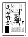
Figure 9a. 2-4 Ton; Single Stage Cool, Two Stage Heat.
CONTROL WIRING LEADS
Refer to Installation
Instructions for Connection
to Indoor Thermostat
XFMR
L1
EAC
M3
COOL
HEAT
HU
M2
M1
HUM
EAC
NEUTRALS
Pin Numbers
P2
3 2 1
6 5 4
Pin Numbers
P1
9 8 7
3 2 1
6 5 4
24V
COM
3A
FUSE
FLAME
(YELLOW)
STATUS
(RED)
T3
T1
T2
*ASCT
L1
T1T2
L2
CONTACTOR
RED
BLACK
BLACK
TRANSFORMER
BROWN
BROWN
BLACK
BLACK
INDUCER
MOTOR
IGNITOR
RED
ORANGE
ORANGE
FLAME
PRESSURE
SWITCH
BLUE
BLUE
BLUE
FLAME
ROLL-OUT
SWITCH
LIMIT
SWITCH
PRIMARY
GAS
VALVE
SECONDARY
GAS VALVE
BROWN
BROWN
BROWN
YELLOW
YELLOW
YELLOW
BROWN
VALVE RELAY
76
5 4 3 2 1
11 7 513
R
1
2
4
3
7
8
6
5
13
14
16
15
11
12
10
9
9
8
7
6
5
4
3
2
1
16
15
14
12
11
10
13
W2
WHITE
WHITE
DUAL CAPACITOR
F
ORANGE
BLUE
BLACK
YELLOW
RED
BLACK
VARIABLE
SPEED
BLOWER
MOTOR
54 23 1
15432
BLACK
WHITE
YELLOW
BLUE
BROWN
ORANGE
RED
VARIABLE SPEED CONTROL
BROWN
WHITE
YELLOW
RED
GREEN
RED
ROOM THERMOSTAT
COMPRESSOR
OUTDOOR
FAN MOTOR
YELLOW
BLACK
LOW
PRESSURE
SWITCH
RED
POWER SUPPLY
R
S
C
GREEN
RC
Y
G
W
GRAY
WGYC
R
R
S
C
R
Note: See Installation
instructions for specific
blower speed setting.
GREEN
W
W
SENSOR
*ASCT-ANTI SHORT CYCLE TIMER
SEE
NOTE 7
YELLOW/BLACK
N NOTES:
1. Disconnect all power before
servicing.
2. For supply connections use copper
conductors only.
3. Not suitable on systems that
exceed 150 V to ground.
4. If any of the original wire as
supplied with the furnace must be
replaced, it must be replaced with
wiring material having a
temperature rating of at least
105°C.
5. For supply wire ampacities and
overcurrent protection, see unit
rating plate.
6. Ensure that wires from the blower
remain connected to the board
thermostat terminals after making
the field thermostat connections.
7. Wiring shown for 2-stage operation
when using a multistage thermo-
stat. Warning-Remove Yellow/Black
wire from primary gas valve and
utilize for wiring furnace for 2
stage operation. See Installation
Instruction for alternate means of
using second stage.
1. Couper le courant avant de faire
letretien.
2. Employez uniquement des
conducteurs en cuivre.
3. Ne convient pas aux installations
de plus de 150 V a la terre.
708333A
FAULT CONDITION STATUS LIGHT (RED)
Power On On
Limit Circuit Open 1 Flash
Pressure Switch Stuck Open with Inducer On 2 Flash
Pressure Switch Stuck Closed with Inducer Off 3 Flash
Ignition Failure (Check Ground) 4 Flash
230 VAC & Neutral Reversed or No Ground 5 Flash
False Flame or Gas Relay Shorted Continuous Flash
Power Off Off
FAULT CONDITION STATUS LIGHT (YELLOW)
Low Flame Sensor Signal Continuous Flash
Flame Present On
Field Wiring
Factory Wiring
Low Voltage
High Voltage

20
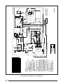
Figure 9b. 5 Ton; Two Stage Cool, Two Stage Heat
N NOTES:
1. Disconnect all power before
servicing.
2. For supply connections use copper
conductors only.
3. Not suitable on systems that
exceed 150 V to ground.
4. If any of the original wire as
supplied with the furnace must be
replaced, it must be replaced with
wiring material having a
temperature rating of at least
105°C.
5. For supply wire ampacities and
overcurrent protection, see unit
rating plate.
6. Ensure that wires from the blower
remain connected to the board
thermostat terminals after making
the field thermostat connections.
7. Wiring shown for 2-stage operation
when using a multistage thermo-
stat. Warning-Remove Yellow/Black
wire from primary gas valve and
utilize for wiring furnace for 2
stage operation. See Installation
Instruction for alternate means of
using second stage.
1. Couper le courant avant de faire
letretien.
2. Employez uniquement des
conducteurs en cuivre.
3. Ne convient pas aux installations
de plus de 150 V a la terre.
710489A
CONTROL WIRING LEADS
Refer to Installation
Instructions for Connection
to Indoor Thermostat
XFMR
L1
EAC
M3
COOL
HEAT
HU
M2
M1
HUM
EAC
NEUTRALS
Pin Numbers
P2
3 2 1
6 5 4
Pin Numbers
P1
9 8 7
3 2 1
6 5 4
24V
COM
3A
FUSE
FLAME
(YELLOW)
STATUS
(RED)
T3
T1
T2
*ASCT
L1
T1T2
L2
CONTACTOR
RED
BLACK
BLACK
TRANSFORMER
BROWN
BROWN
BLACK
BLACK
INDUCER
MOTOR
IGNITOR
RED
ORANGE
ORANGE
FLAME
PRESSURE
SWITCH
BLUE
BLUE
BLUE
FLAME
ROLL-OUT
SWITCH
LIMIT
SWITCH
PRIMARY
GAS
VALVE
SECONDARY
GAS VALVE
BROWN
BROWN
BROWN
YELLOW
YELLOW
YELLOW
BROWN
VALVE RELAY
76
5 4 3 2 1
11 7 513
R
1
2
4
3
7
8
6
5
13
14
16
15
11
12
10
9
9
8
7
6
5
4
3
2
1
16
15
14
12
11
10
13
W2
WHITE
WHITE
DUAL CAPACITOR
F
ORANGE
BLUE
BLACK
YELLOW
RED
BLACK
VARIABLE
SPEED
BLOWER
MOTOR
54 23 1
15432
BLACK
WHITE
YELLOW
BLUE
BROWN
ORANGE
RED
VARIABLE SPEED CONTROL
YELLOW/BLACK
BROWN
WHITE
YELLOW
RED
GREEN
RED
ROOM THERMOSTAT
COMPRESSOR
OUTDOOR
FAN MOTOR
YELLOW
SEE
NOTE 7
BLACK
LOW
PRESSURE
SWITCH
RED
POWER SUPPLY
R
S
C
GREEN
RC
Y
G
W
GRAY
WGY
1C
R
R
S
C
R
Note: See Installation
instructions for specific
blower speed setting.
GREEN
W
W
SENSOR
*ASCT-ANTI SHORT CYCLE TIMER
Y2
BLUE
BLUE
BLUE
BLUE
FAULT CONDITION STATUS LIGHT (RED)
Power On On
Limit Circuit Open 1 Flash
Pressure Switch Stuck Open with Inducer On 2 Flash
Pressure Switch Stuck Closed with Inducer Off 3 Flash
Ignition Failure (Check Ground) 4 Flash
230 VAC & Neutral Reversed or No Ground 5 Flash
False Flame or Gas Relay Shorted Continuous Flash
Power Off Off
FAULT CONDITION STATUS LIGHT (YELLOW)
Low Flame Sensor Signal Continuous Flash
Flame Present On
Field Wiring
Factory Wiring
Low Voltage
High Voltage
Page is loading ...
Page is loading ...
Page is loading ...
Page is loading ...
Page is loading ...
Page is loading ...
Page is loading ...
Page is loading ...
-
 1
1
-
 2
2
-
 3
3
-
 4
4
-
 5
5
-
 6
6
-
 7
7
-
 8
8
-
 9
9
-
 10
10
-
 11
11
-
 12
12
-
 13
13
-
 14
14
-
 15
15
-
 16
16
-
 17
17
-
 18
18
-
 19
19
-
 20
20
-
 21
21
-
 22
22
-
 23
23
-
 24
24
-
 25
25
-
 26
26
-
 27
27
-
 28
28


Westinghouse R4GD-X Installation guide
- Category
- Stoves
- Type
- Installation guide
- This manual is also suitable for
Ask a question and I''ll find the answer in the document
Finding information in a document is now easier with AI
Related papers
Other documents
-
Broan E3 Series Electric Furnace Product information
-
-
Reznor JS4BD Product information
-
Unbranded P6SD-X 3 - 5 Ton, 3 phase Product information
-
-
-
-
-
-