Broan PPH2RF Installation guide

Category
Heat pumps
Type
Installation guide

This manual is also suitable for

15 SEER
Single Package Heat Pump - 2 Stage, R-410A
Q5RF / PPH2RF SERIES
INSTALLATION INSTRUCTIONS
DO NOT DESTROY. PLEASE READ CAREFULLY AND KEEP IN A SAFE PLACE FOR FUTURE REFERENCE.
IMPORTANT
ATTENTION INSTALLERS:
It is your responsibility to know this product better than your customer. This includes being
able to install the product according to strict safety guidelines and instructing the customer on
how to operate and maintain the equipment for the life of the product. Safety should always be
the deciding factor when installing this product and using common sense plays an important
role as well. Pay attention to all safety warnings and any other special notes highlighted in the
manual. Improper installation of the furnace or failure to follow safety warnings could result
in serious injury, death, or property damage.
These instructions are primarily intended to assist qualified individuals experienced in the
proper installation of this appliance. Some local codes require licensed installation/service
personnel for this type of equipment. Please read all instructions carefully before starting the
installation. Return these instructions to the customer’s package for future reference.
2
Important Safety Information ....................................3
Requirements & Codes ..............................................4
General Information ...................................................4
Before You Install this Unit .........................................4
Locating the Heat pump ...........................................4
Air Duct System ........................................................4
Unconditioned Spaces ...........................................5
Heat Pump Installation ...............................................5
Unpacking the Unit ...................................................5
Minimum Clearances .................................................5
Service Access Clearances ..................................5
Clearances to Combustible Materials ...................5
Installing Return & Supply Air Collars .......................5
Return Duct ...........................................................5
Supply Duct ...........................................................5
Locating & Installing the Return Air
Assembly ...................................................................5
Locating & Installing the Supply
Dampers ....................................................................6
Condensate Drainage ...............................................6
Electrical Connections ...............................................7
Pre - Electrical Checklist ...........................................7
Line Voltage ...............................................................7
Grounding..................................................................7
Overcurrent Protection ..............................................7
Blower Speed ...........................................................8
2 - Speed Outdoor Fan Motor ...................................8
Ambient Sensor Mounting .........................................8
Demand Defrost Control............................................9
Thermostat Connections ...........................................9
Electric Heat Package .............................................10
Startup & Adjustments ............................................11
Pre - Start Checklist ................................................11
Start - Up Procedure ...............................................11
Air Circulation ....................................................... 11
System Heating .................................................... 11
System Cooling ....................................................11
Short Cycle Protection .........................................11
Emergency Heat ..................................................11
Adjustment of Refrigerant Charge ........................... 11
Charging the Unit in AC Mode .............................11
Charging the Unit in Heat Mode ........................... 12
Forced Defrost Mode (Field Test) ............................12
Anti Short Cycle Timer Test .....................................12
Heating Mode ....................................................... 12
Cooling Mode .......................................................12
Component Functions .............................................12
Low Pressure Switch ...............................................12
High Pressure Switch ..............................................12
Unit Maintenance ...................................................... 12
Figures & Tables .......................................................13
Figure 8 - Unit Dimensions ..................................13
Table 2 - Physical Data ........................................13
Refrigerant Charging Charts - Cooling Mode .......... 14
Figure 9 - Charging Chart for 2 Ton Units ............14
Figure 10 - Charging Chart for 3 Ton Units ..........14
Figure 11 - Charging Chart for 4 Ton Units ..........15
Figure 12 - Charging Chart for 5 Ton Units ..........15
Wiring Diagrams ...................................................... 16
Figure 13 - W.D. for 2 & 3 Ton Units .....................16
Figure 14 - W.D. for 4 & 5 Ton Units .....................17
3
IMPORTANT SAFETY INFORMATION
Please read all instructions before servicing this equipment.
Pay attention to all safety warnings and any other special
notes highlighted in the manual. Safety markings are
used frequently throughout this manual to designate a
degree or level of seriousness and should not be ignored.
WARNING indicates a potentially hazardous situation that
if not avoided, could result in personal injury or death.
CAUTION indicates a potentially hazardous situation that
if not avoided, may result in minor or moderate injury or
property damage.
WARNING:
ELECTRICAL SHOCK, FIRE OR EXPLOSION
HAZARD
Failure to follow safety warnings exactly could
result in serious injury or property damage.
Improper servicing could result in dangerous
operation, serious injury, death or property
damage.
     
power to the indoor blower.
 
to disconnecting. Reconnect wires correctly.
 
WARNING:
These units are fully charged with R-410A
refrigerant and ready for installation. When
a system is installed according to these
instructions, no refrigerant charging is required.
If repairs make it necessary for evacuation
and charging, it should only be attempted
by qualified, trained personnel thoroughly
familiar with this equipment. Some local codes
require licensed installation service personnel
to service this type of equipment. Under no
circumstances should the homeowner attempt
to install and/or service this equipment. Failure
to comply with this warning could result in
equipment damage, personal injury, or death.
WARNING:
Do not place combustible material on or against
the unit cabinet. Do not place combustible
materials, including gasoline and any other
flammable vapors and liquids, in the vicinity
of the unit.
WARNING:
PROPOSITION 65 WARNING: This product
contains fiberglass wool, a product known
to the state of California to cause cancer.
Disturbing the insulation of this product during
installation, maintenance, or repair will expose
you to fiberglass wool.
 
irritations or may cause lung cancer.
     
irritation, skin sensitization, or other allergic
responses in susceptible individuals.
     
long sleeved shirt, and appropriate breathing
protection when working near this insulation.
If contact with skin occurs, wash immediately
with soap and water. In case of contact with
eyes, flush immediately with water for at
least 15 minutes. Contact a physician if
needed.
WARNING:
The information listed below and on the next
page must be followed during the installation,
service, and operation of this unit. Unqualified
individuals should not attempt to interpret these
instructions or install this equipment. Failure
to follow safety recommendations could result
in possible damage to the equipment, serious
personal injury or death.
• Beforebeginningtheinstallation,verifythattheunit
model is correct for the job. The unit model number
is printed on the data label. Follow all precautions in
the literature, on tags, and on labels provided with
the equipment. Read and thoroughly understand
the instructions provided with the equipment prior to
performing the installation and operational checkout
of the equipment.
Installation of equipment may require brazing
operations. Installer must comply with safety codes
and wear appropriate safety equipment (safety glasses,
work gloves, fire extinguisher, etc.) when performing
brazing operations.
• Usecautionwhenhandlingthisapplianceorremoving
components. Personal injury can occur from sharp
metal edges present in all sheet metal constructed
equipment.
4
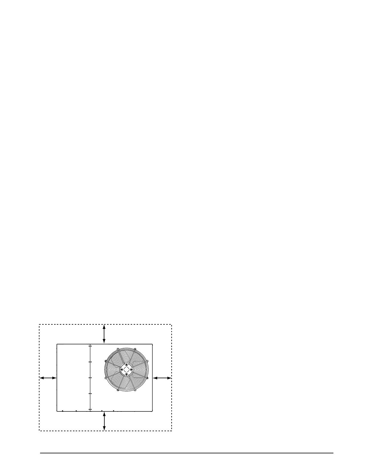
Figure 1. Minimum Unit Clearances
12"
12"
24"
TOP OF UNIT
TO BE
UNOBSTRUCTED
0"
GENERAL INFORMATION
Single packaged heat pumps are ready for easy and
immediate installation and can be readily connected into
the high static duct system of a home. This unit is completely
assembled, wired, and run tested at the factory. The only
connections needed for installation are the supply and
return ducts, the line voltage, and thermostat wiring. Use
of components other than those specified may invalidate
AHRI Certification, Code Agency Listing, and limited
warranty on the air conditioner.

The cooling load of the area to be conditioned must be
calculated and a system of the proper capacity selected.
It is recommended that the area to be conditioned be
completely insulated and vapor sealed.
Check the electrical supply and verify the power supply
is adequate for unit operation. If there is any question
concerning the power supply, contact the local power
company.
All units are securely packed at the time of shipment and
upon arrival should be carefully inspected for damage
prior to installing the equipment at the job site. Verify
coil fins are straight. If necessary, comb fins to remove
flattened or bent fins. Claims for damage (apparent or
concealed) should be filed immediately with the carrier.
Please consult your dealer for maintenance information
and availability of maintenance contracts. Please read
all instructions before installing the unit.
Locating the Heat Pump
• Surveythejobsitetodeterminethebestlocationfor
mounting the outdoor unit.
• Choose an appropriate location that minimizes the
length of the supply and return air ducts.
• Overheadobstructions,poorly ventilatedareas,and
areas subject to accumulation of debris should be
avoided.
• Sufcientclearanceforunobstructedairowthroughthe
outdoor coil must be maintained in order to achieve rated
performance. See Figure 1 for minimum clearances to
obstructions.
• Considerationshould also begivento availabilityof
electric power, service access, noise, and shade.
Air Duct System
Air ducts must be installed in accordance with the standards
of the National Fire Protection Association “Standard for
Installation of Air Conditioning and Ventilation Systems”
(NFPA 90A), “Standard for Installation of Residence Type
Warm Air Heating and Air Conditioning Systems” (NFPA
90B), these instructions, and all applicable codes. NFPA
publications are available by writing to: National Fire
Protection Association, Batterymarch Park, Quincy, ME
02269 or visit www.NFPA.org on the web.
• Designtheductworkaccordingtomethodsdescribed
by the Air Conditioning Contractors of America (ACCA).
• The supply duct system, including the number and
type of registers, will have much more effect on the
performance of the system than any other factor. The
REQUIREMENTS & CODES
• Allelectricalwiringmustbecompletedinaccordance
with local, state & national codes and regulations and
with the National Electric Code (ANSI/NFPA 70) or in
Canada the Canadian Electric Code Part 1 CSA C.22.1.
• The installer must comply with all local codes and
regulations which govern the installation of this type
of equipment. Local codes and regulations take
precedence over any recommendations contained in
these instructions. Consult local building codes and the
National Electrical Code (ANSI CI) for special installation
requirements.
• Thisequipmentcontainsliquidandgaseousrefrigerant
under high pressure. Installation or servicing should only
be performed by qualified trained personnel thoroughly
familiar with this type equipment.
• Air Ducts must be installed in accordance with the
standards of the National Fire Protection Association
“Standards for Installation of Air Conditioning and
Ventilation Systems” (NFPA 90A), “Standard for
Installation of Residence Type Warm Air Heating and Air
Conditioning Systems” (NFPA 90B), these instructions,
and all applicable local codes.
• ConsultTable1(page8),andtheratingplateforthe
proper circulating air flow and temperature rise. It is
important that the duct system be designed to provide
the correct flow rates and external pressure rise. An
improperly designed duct system can result in nuisance
shutdowns, and comfort or noise issues.
• Thisunitisdesignedforoutdoorinstallationsonlyand
should be positioned as described in Locating the Heat
Pump.
• Followall precautions inthe literature,on tags,and
on labels provided with the equipment. Read and
thoroughly understand the instructions provided with
the equipment prior to performing the installation and
operational checkout of the equipment.
• Theinstallershouldbecomefamiliarwiththeunitswiring
diagram before making any electrical connections to
the unit. See the unit wiring label or Figures 13 & 16
(pages 16 & 17).
5
HEAT PUMP INSTALLATION
Unpacking the Unit
It is recommended that the unit be unpacked at the
installation site to minimize damage due to handling.
CAUTION:
Do not tip the unit on its side. Oil may enter
the compressor cylinders and cause starting
trouble. If unit has been set on its side, restore
to upright position and do not run for several
hours. Then run unit for a few seconds. Do this
three or four times with five minutes between
runs.
1. Remove the bands from around the unit.
2. Unfold the top and bottom cap flanges.
3. Carefully remove the top cap and tube.
Minimum Clearances
Minimum clearances MUST be maintained from adjacent
structures to provide room for proper servicing and air
circulation. DO NOT install unit in a confined or recessed
area that will allow discharge air from the unit to re-circulate
into the condenser air inlet, through the coil. See Figure 1.
Service Access Clearances
Blower access panel side .......................................... 24”
Electrical compartment access panel side ............... 12”
Clearance between overhang and top of unit ........ 72”
Clearance around condenser coil area to wall or
shrubs (excludes duct panel side) ............................. 12”
Clearances to Combustible Materials
Supply and return air ducts .........................................0”
Duct connection side ...................................................0”
duct must be sufficiently large to conduct an adequate
amount of air to each register. See Figure 3 (page 6).
• Ductworkshouldbeattacheddirectlytotheunitanges
for horizontal applications.
• Forhighlyresistiveductsystemsitmaybenecessary
to add an additional return air duct and or supply to
achieve maximum performance and prevent coil icing
and refrigerant flood back
Unconditioned Spaces
All duct work passing through unconditioned space must
be properly insulated to minimize duct losses and prevent
condensation. Use insulation with an outer vapor barrier.
Refer to local codes for insulation material requirements.
The heat pump system will not cool or heat the home
if air is lost to the outside through leaks in the duct
system. Ducts that are collapsed or restricted by
foreign objects will also prevent adequate air flow.
Figure 2. Return & Supply Air Collars
Supply Air
14” Duct Dimples
Return Air
Transition Duct Screws
Installing Return & Supply Air Collars
If the supply and return collars are supplied with the unit,
they will be located in the supply duct. They can be easily
positioned over the unit openings (Figure 2) and secured
with sheet metal screws.
• Thediameterofthereturnductcollaris14”.
• Thediameterofthesupplyductcollaris12”.
Before permanently installing the collars, it is
recommended you pre-fit them over the openings first
to determine best fit and alignment.
Return Duct
1. Align the slots with the holes in the collar and install
two screws.
2. Position the collar over the opening and align the
four holes in the collar with the four dimples or holes
(depending on unit model) in the panel.
3. Using self-drilling screws (10-16x.5) attach the collar
to the rear panel.
Supply Duct
1. Position the supply duct collar so the edge of the unit
opening fits between the flange and the bead.
2. Overlap the collar ends keeping the small screw holes
underneath.
3. Align the holes in the crimped area and install one
screw. NOTE: It may be necessary to loosen the four
screws that hold the transition duct in order to install the
supply fitting. Re-tighten when installation is complete.
4. Tap collar (if necessary) to ensure engagement with
unit opening and install second screw.
5. Tighten first screw and rotate collar clockwise so joint
is near three o’clock position.
Locating & Installing the Return Air Assembly
To simplify installation, locate and install the return air
assembly first. If desired, the return opening can be
located inside a closet with louvered doors that has an
open area equal to or greater than a 12” x 20” grille. The
return air grille can be placed in the wall of a closet and
the air ducted into the filter box through a boxed-in area
at the closet floor level. Make sure the filter is readily
accessible.
6
Locating & Installing the Supply Damper(s)
CAUTION:
If installing this air conditioning system in
conjunction with a furnace, a damper must be
installed in the furnace base assembly to prevent
cold air from being discharged around the heat
exchanger. Damage to the heat exchanger and
asphyxiation may occur if a damper is not
installed.
Check with the furnace manufacturer for damper
requirements. Failure to install the required
furnace damper may invalidate code agency
listing and limited warranty on the furnace.
Figure 4. Drain Trap
P-Trap
Elbow
MULTIPLE DUCT APPLICATION
SINGLE DUCT APPLICATION
Figure 3. Typical Duct Applications
Condensate Drainage
A 3/4” condensate fitting extends out of the side of the
unit as shown in Figure 4. The drain trap, shipped in the
electrical compartment, must be installed to prevent water
from collecting inside the unit.
1. Thread the elbow provided with the unit into the drain
connection until hand tight.
2. Connect the condensate tubing onto the fitting, forming
a trap near the drain connection.
3. Route the condensate tube from the trap to a suitable
drain. NOTE: For proper drainage, make sure the trap
is level to the ground and tubing outlet is below trap
level.
7
ELECTRICAL CONNECTIONS
WARNING:
To avoid electric shock, personal injury, or death,
turn off the electric power at the disconnect
or the main service panel before making any
electrical connections.
• Electrical connections must be in compliance with
all applicable local codes and ordinances, and with
the current revision of the National Electric Code
(ANSI/NFPA 70).
• ForCanadianinstallationstheelectricalconnections
and grounding shall comply with the current Canadian
Electrical Code (CSA C22.1 and/or local codes).
Pre-Electrical Checklist:
Verify that the voltage, frequency, and phase of the
supply source match the specifications on the unit
rating plate.
Verify that the service provided by the utility is sufficient
to handle the additional load imposed by this equipment.
refer to the unit wiring label for proper high and low
voltage wiring.
Verify factory wiring is in accordance with the unit wiring
diagram (Figures 13 & 14, pages 16 & 17). Inspect for
loose connections.

• Itisrecommendedthatthelinevoltagetotheunitbe
supplied from a dedicated branch circuit containing the
correct fuse or circuit breaker for the unit.
• An electrical disconnect must be located within
sight of and readily accessible to the unit. This
switch shall be capable of electrically de-energizing the
outdoor unit. See unit data label for proper incoming field
wiring. Any other wiring methods must be acceptable
to authority having jurisdiction.
• Providepowersupplyfortheunitinaccordancewith
the unit wiring diagram, and the unit rating plate.
• Connecttheline-voltageleadstotheterminalsonthe
contactor inside the control compartment. Extend leads
through power wiring hole (Figure 5). Connect L1 & L2
directly to the contactor.
• Useonlycopperwireforthelinevoltagepowersupply
to this unit. Use proper code agency listed conduit and
a conduit connector for connecting the supply wires to
the unit. Use of rain tight conduit is recommended.
• Seetheunitwiringlabelforproperhighandlowvoltage
wiring. Make all electrical connections in accordance
with all applicable codes and ordinances.
CAUTION:
Label all wires prior to disconnection when
servicing controls. Wiring errors can cause
    
proper operation after servicing.
• Units are shipped from the factory wired for 240 volt
transformer operation. For 208V operation, remove the
lead from the transformer terminal marked 240V and
connect it to the terminal marked 208V.
Grounding
WARNING:
The unit cabinet must have an uninterrupted
or unbroken electrical ground to minimize
personal injury if an electrical fault should occur.
Do not use gas piping as an electrical ground!
This unit must be electrically grounded in accordance
with local codes or, in the absence of local codes, with
the National Electrical Code (ANSI/NFPA 70) or the CSA
C22.1 Electrical Code. Use the grounding lug provided in
the control box for grounding the unit.
Overcurrent Protection
Overcurrent protection must be provided at the branch
circuit distribution panel and sized as shown on the unit
rating label and according to applicable local codes.
Generally, the best fuse or breaker for any heat pump
is the smallest size that will permit the equipment to run
under normal usage and provide maximum equipment
protection. Properly sized fuses and breakers also prevent
nuisance trips during unit startup. If a fuse blows or a
breaker trips, always determine the reason. Do not
arbitrarily install a larger fuse or breaker and do not,
in any case, exceed the maximum size listed on the
data label of the unit.
Figure 5. Power Entry


8

For optimum system performance and comfort, it may be
necessary to change the factory speed setting. See Table
1 below for factory settings. NOTE: This model has a High
Efficiency ECM Motor with 5 speed taps.
WARNING:
To avoid electric shock, personal injury, or death,
turn off the electric power at the disconnect
or the main service panel before making any
electrical connections.
1. Disconnect all electrical power to the unit and remove
the service panel.
CAUTION:
Label all wires prior to disconnection when
servicing controls. Wiring errors can cause
    
proper operation after servicing.
2. Locate the orange, black and red wires terminated to
the blower motor. The orange wire controls the low
speed cooling and heating operations, the black wire
controls high speed cooling and heating operations and
the red wire controls the electric heating operation.
CAUTION:
To avoid personal injury or property damage,
make certain that the motor leads cannot come
into contact with any metal components of the
unit.
3. Verify the required speed from the airflow data found
in Table 1. Place appropriate wire on the appropriate
motor speed tap for the required airflow.
4. Check all factory wiring per the unit wiring diagram and
inspect the factory wiring connections to be sure none
loosened during shipping or installation.
2-Speed Outdoor Fan Motor
(Select Models)
If the unit utilizes a 2-speed condenser fan motor, this
motor will operate on low speed when in low cooling/
heating, and on high speed when in high cooling/heating.
Ambient Sensor Mounting
For optimum performance of the heat pump system, the
ambient sensor (Figure 6, page 9) must be mounted on
the outside of the unit.
1. Remove the mounting bracket and all hardware included
in the packet.
2. Remove star bushing from 7/8” hole in corner panel of
the unit.
Model
Number
Motor
Tap
External Static Pressure Drop (in WC)
0.1 0.2 0.3 0.4 0.5 0.6 0.7 0.8
X24K
TAP T1* 990 790 560 540
TAP T2** 1040 850 600 550 500
TAP T3 1080 920 800 720 680 620 570 520
TAP T4*** 1160 1100 1040 1000 960 900 850 820
TAP T5 1330 1300 1250 1200 1170 1130 1080 1030
X36K
TAP T1* 1020 840 600 500
TAP T2 1060 900 750 700 650 600 540 500
TAP T3** 1280 1240 1200 1180 1140 1100 1070 1010
TAP T4*** 1480 1450 1420 1390 1360 1320 1290 1240
TAP T5 1580 1550 1520 1480 1450 1420 1380 1350
X48K
TAP T1* 1150 1090 1030 1000 950 900 850 800
TAP T2 1300 1270 1240 1200 1160 1120 1090 1050
TAP T3*** 1460 1430 1400 1370 1340 1300 1250 1200
TAP T4** 1520 1480 1450 1420 1390 1360 1330 1300
TAP T5 1740 1710 1680 1650 1620 1590 1540 1500
X60K
TAP T1 1150 1100 1060 1030 980 950 900 870
TAP T2* 1250 1200 1170 1150 1130 1100 1060 1020
TAP T3*** 1560 1530 1500 1470 1450 1420 1390 1360
TAP T4** 1750 1700 1670 1630 1600 1580 1560 1530
TAP T5 1960 1930 1900 1860 1830 1800 1770 1740
* Denotes factory set low cooling & heating speed
** Denotes factory set high cooling & heating speed
*** Denotes factory set electric heating speed
Table 1. Airflow Data
9
Table 2. Demand Defrost Curve Profiles
Jumper
Position
Minimum Time

(minutes)
Terminate
Temperature
(° F)
Compressor
Delay
Function
1 20 40 NO
2 20 40 YES
3 20 75 NO
4 20 75 YES
Star Bushing
Bolt
Nut
Ambient Sensor
Plastic Clip
Nut
Figure 6. Ambient Sensor Mounting
3. Route the ambient sensor through the 7/8” hole in the
corner panel of the unit, and then through the 7/8” hole
in the mounting bracket.
4. Route the sensor through the star bushing. Use the star
bushing to secure the mounting bracket to the unit.
5. Secure the ambient sensor inside the plastic clip and
secure it to the mounting bracket with the screw and
nut provided.
6. Install one spacer next between the plastic clip and
mounting bracket.
7. Bend the mounting bracket into position. Install the
mounting bracket to the unit using the screw in the
corner panel.
and 4 minutes, unless the coil temperature is above
the selected terminate temperature.
• The system can be manually forced into defrost
mode at any time by shorting the TEST terminals on
the demand defrost board together for more than 9
seconds. The coil temperature sensor does not need
to be cold when the unit is forced into defrost. After the
TEST input is shorted, the defrost mode will terminate
in 13.7 minutes, if the coil temperature is above the
terminate set-point, or when the Y input is removed,
whichever occurs first.
NOTE: If a demand curve is selected which has a 30
second compressor time delay, the delay is reduced to
10 seconds in TEST mode.
Demand Defrost Control
The demand defrost board controls the defrost cycle in
response to ambient temperature, outdoor coil temperature
and accumulated compressor run time. The heat pump is
allowed to operate in the heating mode until the combination
of outdoor ambient and outdoor coil temperatures indicate
that defrosting is necessary, based on the programmed
defrost curve. There are four preprogrammed defrost
curves on the board.
• Ajumperpinisusedtoswitchbetweenthedifferent
curves. The default jumper position is curve 1 and is the
recommended setting for most standard applications.
See Table 2 for additional defrost curves settings.
• Thefactorydefaultsettingdoesnotincludea30second
compressor delay function and has a 40 ° F defrost
terminate temperature. If additional defrost time is
needed, a higher terminate temperature is available
by selecting a different demand curve. NOTE: The 30
second compressor delay occurs when the unit enters
defrost and exits defrost. The delay function is optional
and based on the demand curve selected.
• The standard defrost cycle will terminate after 13
minutes and 39 seconds or when the coil temperature
reaches its terminate temperature, whichever occurs
first.
• Thedefrostboardisequippedwitha5minuteAnti-Short
Cycle Timer (ASCT). The compressor will not turn on
until it reaches the minimum 5 minute off time.
• Thecontrolcontainsaforced-defrostfeature,which
places the system into defrost mode every 6 hours
Thermostat Connections
• Thisheatpumprequiresa2-stageCoolingand3stage
heating thermostat if electric heat is field installed. The
heat-cool thermostat prevents simultaneous operation
of the heating and cooling units and is equipped with
an ON-AUTO fan mode that allows the home owner
to operate the indoor blower when only air circulation
is desired.
• Thecontrolcircuitwiringmustcomplywiththecurrent
provisions of the NEC (ANSI/NFPA 70) and with
applicable local codes having jurisdiction. Thermostat
connections should be made in accordance with the
instructions supplied with the thermostat and the indoor
equipment.
• Thelowvoltagewiresmustbeproperlyconnectedto
the units low voltage terminal block.
1. Route 24V control wires through the sealing grommet
(Figure 5, page 7) near the power entrance.
2. Connect the control wires to the defrost board and
blower relay wire (Figure 7, page 10).
• Several thermostatoptions are available depending
on the accessories installed with the unit. Select a
thermostat that operates in conjunction with the installed
accessories.
• The thermostat should be mounted about 5 feet
above the floor on an inside wall. DO NOT install the
thermostat on an outside wall or any other location
where its operation may be adversely affected by radiant
heat from fireplaces, sunlight, or lighting fixtures, and
convective heat from warm air registers or electrical
appliances. Refer to the thermostat manufacturer’s
instruction sheet for detailed mounting information.
10
Electric Heat Package (optional)
This heat pump is shipped without an auxiliary electric
heat kit installed. If electric heat is desired, an accessory
Heater Kit must be field installed. See Specifications Sheet
for available kits and their application.
Figure 7. Typical Heat Pump Thermostat Connections
Typical Wiring (Field Supplied) for 2-Stage Heat, 2-Stage Electric Heat w/ Optional Outdoor T-Stat
Typical Wiring (Field Supplied) for 2-Stage Cool, 1 Stage Electric Heat
E
O
G
R
Y1
INDOOR THERMOSTAT
SUB-BASE
Y2
W1
C
1
2
3
4
5
6
7
8
9
Brown
Orange
Accessory
Heat Plug
AMBIENT
SENSOR
COIL
SENSOR
TEST
LRCYO
W2
IN
W2
OUT
COND FAN
AMBIENT
AMBG
COILG
COIL
DEMAND
DEFROST CONTROL
BOARD
M
PRESS
SW
REV
VALVE
Demand Defrost Board
Outdoor Thermostat
(optional)
Blower Relay
Compressor Solenoid
ECM Motor (if applicable)
Y1 = 1st Stage Heat Pump
Y2 = 2nd Stage Heat Pump
W1 = 1st Stage Auxillary Heat
Green
(from blower relay)
1
2
3
4
5
6
7
8
9
Brown
Orange
Accessory
Heat Plug
AMBIENT
SENSOR
COIL
SENSOR
TEST
LRCYO
W2
IN
W2
OUT
COND FAN
AMBIENT
AMBG
COILG
COIL
DEMAND
DEFROST CONTROL
BOARD
M
PRESS
SW
REV
VALVE
Demand Defrost Board
Outdoor Thermostat (optional)
Y1 = 1st Stage Heat Pump
Y2 = 2nd Stage Heat Pump
W1 = 1st Stage Auxillary Heat
W2 = 2nd Stage Auzillary Heat
E
O
G
R
Y1
INDOOR THERMOSTAT
SUB-BASE
Y2
W1
C
W2
Blower Relay
Compressor Solenoid
ECM Motor (if applicable)
Green
(from blower relay)
• Selectthecorrectsizeheatpackagefortheinstallation.
• Followinstallationinstructionsprovidedwitheachheater
kit.
• Installationismosteasilyaccomplishedbeforemaking
duct or electrical connections.
• RefertoTable1(page8)forblowerspeeds
11
STARTUP & ADJUSTMENTS
Pre-Start Checklist
The following check list should be observed prior to
starting the unit.
Is the unit level? Unit should be level or slightly slanted
toward the drain for proper condensate drainage.
Is the unit installed with the proper clearances as listed
in Figure 1 (page 4)?
Is the wiring correct according to the wiring diagram
and electrical codes?
Are all the wiring connections tight? Check the
condenser fan to make sure it turns freely.
Is the overcurrent protection properly sized?
Is the thermostat wired correctly? Is it installed in a
proper location?
Start-Up Procedure
The control circuit consists of an anti-short cycle timer
that will not let the compressor start at power up before
five minutes have elapsed.
1. Set the system mode to OFF and the temperature
mode to its highest setting.
2. Turn power on at the disconnect switch.
3. Set the system mode to ON or COOL.
4. Set the temperature mode below room temperature.
Verify that the indoor blower, outdoor fan, and
compressor energize and the cooling function starts.
5. Verify the discharge air grilles are adjusted and the
system air is balanced.
6. Verify the duct work has no air leaks.
7. Verify the condensate drain is installed correctly and
functions properly.
8. Set the temperature mode above room temperature.
The unit should stop.
9. Instruct the homeowner on unit and thermostat operation
and filter servicing.
Air Circulation
Leave the thermostat system mode on OFF, and set the
fan mode to ON. Blower should run continuously. Check
the air delivery at the supply registers and adjust register
openings for balanced air distribution. Examine ductwork
for leaks or obstruction if insufficient air is detected.
Set the thermostat fan mode to AUTO. The blower should
stop running.
System Heating
Set the thermostat system mode to HEAT and the fan mode
to AUTO. Change the thermostat temperature selector
above the existing room temperature and check for the
discharge of warm air at the supply registers.
System Cooling
Set the thermostat’s system mode to COOL and the
fan mode to AUTO. Change the thermostat temperature
selector below the existing room temperature. Allow the
cooling system to operate for several minutes and check
for the discharge of cool air at the supply registers.
Short Cycle Protection
The control circuit is equipped with a time-delay feature
for protection against short cycling. With the system
operating in the cooling mode, gradually raise the
thermostat temperature setting until the system de-
energizes. Immediately lower the thermostat temperature
to the original setting and verify that the indoor blower is
energized. After approximately 5 minutes, the compressor
and the outdoor fan will energize.
Emergency Heat
1. Set the thermostat’s system mode to EM HT and the
fan mode to AUTO (intermittent air) or ON (continuous
air).
2. Set the thermostat’s temperature selector above the
existing room temperature and check the following:
• Thethermostatauxiliaryheatlight(RED)ison.
• TheACcompressorandthefanshouldnotrun;low
voltage circuit remains energized.
• Theblowerrunsaccordingtothethermostat’sfan
mode setting.
Adjustment of Refrigerant Charge
CAUTION:
This heat pump contains liquid and gaseous
refrigerant under pressure. Adjustment of
refrigerant charge should only be attempted
by qualified, trained personnel thoroughly
familiar with the equipment and safe responsible
refrigerant handling procedures. Under no
circumstances should the homeowner attempt
to install and/or service this equipment. Failure
to comply with this warning could result in
equipment damage, personal injury, or death.
• Theunitmustbechargedwhilebothrstandsecond
stages are operating.
• Toachieveratedcapacityandefciencythecompressor
must be exposed to refrigerant for at least 24 hours
prior to running and then must be run for a minimum of
12 hours. If Charging in Cooling Mode, see Refrigerant
Charging Charts (Figures 9 - 12, pages 14 & 15).
Charging the Unit in AC Mode with Outdoor
Temperatures Above 65F
1. With the system operating at steady-state, measure the
liquid refrigerant pressure in psig at the service valve.
2. Measure the liquid refrigerant temperature (° F) at the
service valve.
3. For the temperature measured, determine the required
liquid refrigerant pressure from the appropriate charging
charts.
• Ifthepressuremeasuredinstep1isgreaterthan
the required liquid refrigerant pressure determined in
step 3, then there is too much charge in the system.
Remove refrigerant and repeat steps 1 through 3
until the system is correctly charged.
12
• Ifthepressuremeasuredinstep1islessthanthe
required liquid refrigerant pressure determined in
step 3, then there is too little charge in the system.
Add refrigerant and repeat steps 1 through 3 until
the system is correctly charged.
Charging the Unit in Heating Mode
1. Evacuate the refrigerant system.
2. Weigh in the proper charge as indicated on the unit
label. Unit charge MUST be verified in cooling season.
3. Verify the unit is operating properly according to the
System Heating section on page 11.
Forced Defrost Mode (Field Test)
• When the TEST terminals are shorted with the Y input
active and pressure switches closed, the ACST will
be eliminated and the compressor contactor output
energizes within 2 seconds. When the TEST terminals
are shorted for more than 9 seconds with the Y input
active, the control will be placed into a forced defrost
mode.
NOTE: The coil temperature sensor does not need to
be cold when the unit is forced into defrost.
• After the TEST input is shorted, the defrost mode
will terminate in 13.7 minutes or less or when the coil
temperature is above the terminate set point or when
the thermostat Y input is removed, whichever occurs
first.
Anti Short Cycle Timer Test
The 5 minute time delay feature can be bypassed by
shorting the TEST pins together.
Heating Mode
When the TEST pins are shorted together for more than
1 second, the control will switch between defrost mode
and heating mode as described in the Forced Defrost
Mode procedure section.
Cooling Mode
When the TEST pins are shorted together for more than
1 second, the Anti Short Cycle Timer will be bypassed.
COMPONENT FUNCTIONS
Low Pressure Switch
The low pressure switch is factory installed and located in
the suction line internal to the unit. The switch is designed
to protect the compressor if a loss of charge occurs. Under
normal conditions, the switch is closed.
If the suction pressure falls below 5 psig, then the switch will
open and de-energize the unit. The switch will close again
once the suction pressure increases above 20 psig. The low
pressure switch interrupts the thermostat inputs to the unit.
NOTE: When the switch opens and then closes, there
will be a 5 minute short cycling delay before the unit can
energize.
High Pressure Switch
The high pressure switch is factory installed and located
in the compressor discharge line internal to the unit. The
UNIT MAINTENANCE
WARNING:
To prevent electrical shock, personal injury,
or death, disconnect all electrical power to
the unit before performing any maintenance
or service. The unit may have more than one
electrical supply.
Proper maintenance is important to achieve optimum
performance from the heat pump. The ability to properly
perform maintenance on this equipment requires certain
mechanical skills and tools. If you do not possess these
skills, contact your dealer for maintenance. Consult your
local dealer about the availability of maintenance contracts.
Routine maintenance should include the following:
• Inspectandcleanorreplaceairltersatthebeginning
of each heating and cooling season, or more frequently
if required.
• Inspectthecondensatedrainandoutdoorcoilatthe
beginning of each cooling season. Remove any debris.
Clean the outdoor coil and louvers as necessary using
a mild detergent and water. Rinse thoroughly with water.
• Inspecttheelectricalconnectionsfortightnessatthe
beginning of each heating and cooling season. Service
as necessary.
CAUTION:
The unit should never be operated without a
filter in the return air system. Replace disposable
filters with the same type and size.
• Donotattempttoaddadditionaloiltomotorsunequipped
with oil tubes. The compressor is hermetically sealed
at the factory and does not require lubrication.
switch is designed to de-energize the system when very
high pressures occur during abnormal conditions. Under
normal conditions, the switch is closed.
If the discharge pressure rises above 650 psig, the switch
will open and de-energize the unit. The switch will close
again once the discharge pressure decreases to 460
psig. The high pressure switch interrupts the thermostat
inputs to the unit. NOTE: When the switch opens and
then closes, there will be a 5 minute short cycling delay
before the unit can energize.
13
9.15
9.04
17.50
14" diameter
Return Duct
Opening
12" diameter
Supply Duct
Opening
3.0
5.5
1"
3.15
A
B

L
W
18.01
Electric Heater Power Supply
Power Supply
Low Voltage Supply
Control
Access
Panel
Blower Access Panel
H
17.86
15.36
10.10
3/4" NPT
Drain Connection
1"
12.13
1.38
3.2
3.2 5.29

Model Number Length (L) Width (W) Height (H) A
X24K 49 35 30.2 40.15 7.61
X36K 49 35 30.2 35.02 2.48
X48K 49 35 38.2 35.02 2.48
X60K 63 35 38.2 35.02 2.48
Table 3. Physical Data
Figure 8. Unit Dimensions


14
REFRIGERANT CHARGING CHARTS - COOLING MODE
Figure 10. Charging Chart for 3 Ton Units
200
225
250
275
300
325
350
375
400
425
450
475
500
525
550
575
600
70 75 80 85 90 95 100105 110115 120125 130135 140
LIQUID PRESSURE (PSIG)
LIQUID TEMPERATURE (F)
X36K CHARGING CHART
Remove refrigerant when above curve
Add refrigerant when below curve
Figure 9. Charging Chart for 2 Ton Units
200
225
250
275
300
325
350
375
400
425
450
475
500
525
550
575
600
70 75 80 85 90 95 100105 110115 120125 130135 140
LIQUID PRESSURE (PSIG)
LIQUID TEMPERATURE (F)
Remove refrigerant when above curve
Add refrigerant when below curve
X24K CHARGING CHART
15
REFRIGERANT CHARGING CHARTS - COOLING MODE
Figure 12. Charging Chart for 5 Ton Units
200
225
250
275
300
325
350
375
400
425
450
475
500
525
550
575
600
70 75 80 85 90 95 100105 110115 120125 130135 140
LIQUID PRESSURE (PSIG)
LIQUID TEMPERATURE (F)
X60K COOLING CHARGING CHART
Remove refrigerant when above curve
Add refrigerant when below curve
Figure 11. Charging Chart for 4 Ton Units
200
225
250
275
300
325
350
375
400
425
450
475
500
525
550
575
600
70 75 80 85 90 95 100105 110115 120125 130135 140
LIQUID PRESSURE (PSIG)
LIQUID TEMPERATURE (F)
X48K CHARGING CHART
Remove refrigerant when above curve
Add refrigerant when below curve
16
3. Not sutiable on systems that exceed 150V to ground.
4. For replacement wires use conductors suitable for 105°C.
208/230VQ5RF/PPH2RF SERIES SMALL PACKAGE H/P W/DEMAND DEFROST
2 TON AND 3 TON
60HZ/SINGLE PHASE
1. Disconnect all power before servicing.
2. For supply connections use copper conductors only.
3. Not sutiable on systems that exceed 150V to ground.
4. For replacement wires use conductors suitable for 105°C.
5. Unit requires a two stage cooling/heating thermostat
which uses “G” to call for blower.
1. Couper le courant avant de faire letretine.
2. Employez uniquement des conducteurs en cuiver.
3. Ne convient pas aux installations de plus de 150V a la terre.
FIELD WIRING
LEGEND:
LOW VOLTAGE
HIGH VOLTAGE
WIRING DIAGRAM
NOTES:
TEST
7110650
0110
¢711065«¤
L2
L1
T2
T1
LR
C
O
W2
IN
W2
OUT
COND
AMBIENT
AMBG
COILG
COIL
DEMAND
DEFROST CONTROL
BOARD
REV
VALVE
Y
SW
PRESS
M
C
S
R
C
R
S
C
H
F
DAUL
CAPACITOR
OUTDOOR
MOTOR
COMPRESSOR
TRASFORMER
240V
24V
COM
RED
YELLOW
BLACK
BLACK
ORANGE
BLUE
COMPRESSOR
CONTACTOR
TO T-STAT
BLUE
FAN
REVERSING VALVE
COIL
YELLOW
YELLOW / BLACK
BLACK
BLACK
G
N
L
T4
T2
T3
C
T5
T1
4
3
2
1
8
7
6
5
9
HIGH SPEED
BLOWER RELAY
(24V)
BLOWER
RELAY
BLOWER
MOTOR
SEE TABLE FOR FACTORY
SET BLOWER WIRING
YELLOW / BLACK
YELLOW
BLUE
BLACK
YELLOW
ORANGE
BROWN
BLACK
RED
ORANGE
GREY
GREY
GREEN
YELLOW
BLACK
WHITE
RED
RED
RED
RED
BLACK
YELLOW
BLUE
BLACK
BLACK
BLUE
TO “G” ON
T-STAT
AMBIENT
THERMISTOR
COIL
THERMISTOR
3 AMP FUSE
TO “W2” ON
T-STAT
HIGH PRESSURE
SWITCH
LOW PRESSURE
SWITCH
(SELECT MODELS ONLY)
FACTORY SET INDOOR MOTOR WIRING
BLACK WIRE IS HIGH SPEED COOLING/HEATING
ORANGE WIRE IS LOW SPEED COOLONG/HEATING
RED WIRE IS AUX. HEATING SPEED (ELECTRIC HEAT)
REFER TO INSTALLATION INSTRUCTIONS FOR CFM DATA
MODEL
ORANGE
WIRE
BLACK
WIRE
RED
WIRE
X24K T2 T3 T4
X36K T1 T3 T4
BLUE
BLUE
YELLOW
GREEN / YELLOW
TO “Y2”
ON
T-STAT
Figure 13. Wiring Diagram - 2 & 3 Ton Units
WIRING DIAGRAMS
17
NOTES:
FIELD WIRING
LEGEND:
LOW VOLTAGE
HIGH VOLTAGE
208/230V
Q5RF/PPH2RF SERIES SMALL PACKAGE H/P W/DEMAND DEFROST
4 TON AND 5 TON
60HZ/SINGLE PHASE
1. Disconnect all power before servicing.
2. For supply connections use copper conductors only.
3. Not sutiable on systems that exceed 150V to ground.
4. For replacement wires use conductors suitable for 105°C.
5. Unit requires a two stage cooling/heating thermostat
which uses “G” to call for blower.
1. Couper le courant avant de faire letretine.
2. Employez uniquement des conducteurs en cuiver.
3. Ne convient pas aux installations de plus de 150V a la terre.
WIRING DIAGRAM
7110660
0110
L2
L1
T2
T1
G
N
L
T4
T2
T3
C
T5
T1
Y1
L1
ECM
Y2
L2
C
4
3
2
1
8
7
6
5
9
LR
C
O
W2
IN
W2
OUT
DF1
AMBIENT
AMBG
COILG
COIL
DEMAND
DEFROST CONTROL
BOARD
REV
VALVE
Y
SW
PRESS
M
C
S
R
C
H
F
DAUL
CAPACITOR
OUTDOOR
MOTOR
COMPRESSOR
TRASFORMER
240V
24V
HIGH SPEED
BLOWER RELAY
(24V)
BLOWER
RELAY
BLOWER
MOTOR
COM
RED
BLACK
BLACK
BROWN
COMPRESSOR
CONTACTOR
SEE TABLE FOR FACTORY
SET BLOWER WIRING
TO T-STAT
BLUE
DF2
YELLOW
WHITE
REVERSING VALVE
COIL
BLACK
BLACK
YELLOW / BLACK
YELLOW
YELLOW / BLACK
BLUE
BLUE
YELLOW
YELLOW
BLACK
YELLOW
ORANGE
BROWN
BLACK
RED
GREY
GREY
GREEN
BLACK
WHITE
RED
RED
RED
RED
BLACK
YELLOW
BLUE
BLACK
BLUE
BLACK
3 AMP FUSE
TO “W3” ON
T-STAT
TO “G” ON
T-STAT
AMBIENT
THERMISTOR
COIL
THERMISTOR
FACTORY SET INDOOR MOTOR WIRING
BLACK WIRE IS HIGH SPEED COOLING/HEATING
ORANGE WIRE IS LOW SPEED COOLONG/HEATING
RED WIRE IS AUX. HEATING SPEED (ELECTRIC HEAT)
REFER TO INSTALLATION INSTRUCTIONS FOR CFM DATA
MODEL
ORANGE
WIRE
BLACK
WIRE
RED
WIRE
X48K T1 T4 T3
X60K T2 T4 T3
YELLOW
GREEN / YELLOW
BLUE
BLUE
BLUE
LOW PRESSURE
SWITCH
(SELECT MODELS ONLY)
HIGH PRESSURE
SWITCH
¢711066#¤
TO “Y2”
ON
T-STAT
ORANGE
Figure 14. Wiring Diagram - 4 & 5 Ton Units
18
19
 (Replaces 709185A)
Specifications & illustrations subject to change without notice or incurring obligations.
O’ Fallon, MO | Printed in U.S.A. (06/11)
INSTALLATION / PERFORMANCE CHECK LIST
REFRIGERATION SYSTEM:
Was unit given 24 hr warm up
period for crankcase heaters
(if applicable)?
YES NO
Stage-1 Liquid Pressure (high side) _____________
Stage-1 Suction Pressure (low side) _____________
Has the owner’s information
been reviewed with the
customer?
YES NO
Has the Literature Package
been left with the unit?
YES NO
INSTALLATION ADDRESS:
CITY ________________ STATE _____________
UNIT MODEL # _____________________________
UNIT SERIAL # _____________________________
Unit Installed Minimum
clearances per Figure 1
(page 4)?
YES NO
INSTALLER NAME:
CITY ________________
STATE ___________
PROPOSITION 65 WARNING: This product
contains chemicals known to the state of
California to cause cancer, birth defects or
other reproductive harm.
WARNING:
ELECTRICAL SYSTEM:
Electrical connections tight? YES NO
Line voltage polarity correct? YES NO
Rated Voltage: ________________________ VOLTS
L1-L2 Volts: __________________________ VOLTS
Has the thermostat been
calibrated?
YES NO
Is the thermostat level? YES NO
Is the heat anticipator setting
correct?(If Applicable)
YES NO
  • Page 1 1
  • Page 2 2
  • Page 3 3
  • Page 4 4
  • Page 5 5
  • Page 6 6
  • Page 7 7
  • Page 8 8
  • Page 9 9
  • Page 10 10
  • Page 11 11
  • Page 12 12
  • Page 13 13
  • Page 14 14
  • Page 15 15
  • Page 16 16
  • Page 17 17
  • Page 18 18
  • Page 19 19
  • Page 20 20

Broan PPH2RF Installation guide

Category
Heat pumps
Type
Installation guide
This manual is also suitable for

Ask a question and I''ll find the answer in the document

Finding information in a document is now easier with AI