Page is loading ...

UFR1001E 12420-0751-00 Page
1
/ 8 www.ziehl.de
from Firmware:0-01
Short Operating Manual UFR1001E updated:120522WL/Fz
- NA-protection according to VDE-AR-N 4105, power generators at the low voltage grid
- for use in power generators at the medium voltage grid according to BDEW
- with selectable vector shift detection
Operating controls
1
Test button
Press
shortly
Output relays de-energize immediately. If Y1+Y2 are connected and the feedback
signal is activated, the tripping time is displayed as long as no button is actuated
2
LEDs Frequency / voltage, above / below threshold (red)
ON, 8AL 8or 8AL M8
Above / below threshold
Flashing, 8AL 88or 8AL M8
OFF-delay 8dof 8 active
3
LED Vektor shift (VSR, red)
ON, 8AL 8
Threshold value for vector shift exceeded
Flashing, 8AL 8
OFF-delay 8dof 8 active
4
LEDs Relay status (yellow)
OFF
Relays de-energized
ON
Relays energized
5
Digital display 4-digit (red)
Depending on program, display of current voltage, frequency, vector shift, average value
Display of alarm message 8AL 8, 8aL M8
Display of error with error code e.g. 8Err98
6
LED Time (yellow)
ON
A time is displayed
7
Backmost decimal point (red)
OFF
Display mode
Lightning
Menu mode
Flashing
Configuration mode
8
Set / Reset button (in display mode, normal state)
Press shortly
Display of next measured value / alarm counter
Press for > 2 s
Reset, quit error messages
Press for > 4 s
Display of program, e.g. 8Pr 18
Press for > 10 s
Display of firmware version, e.g. 80-018
Temperature-Relays, Grid-Relays, Digital Panelmeters MINIPAN, Switching Relays and Controls, Transducers
ZIEHL industrie – elektronik GmbH + Co KG
Daimlerstraße 13, D – 74523 Schwäbisch Hall
+ 49 791 504-0, in[email protected], www.ziehl.de
- Archive document -

UFR1001E 12420-0751-00 Page
2
/ 8 www.ziehl.de
9
Up / Down button (in display mode, normal state)
Press shortly
Change to the menu mode, display of alarm memory (Down) /
cumulative time of alarms (Up), additional pushing of Set button for ≥ 2 s
makes a reset of the stored values
Press for > 2 s
Display of MAX (Up) / MIN (Down) measured values, additional pushing
of Set button for ≥ 2 s deletes the stored values
10
LEDs Allocation of the measured value (yellow)
LEDs
Measured value
Lx and N ON
Voltage (L1 against N, L2 against N, L3 against N)
Lx and Ly ON
Voltage (L1 against L2, L2 against L3, L1 against L3)
Lx flashing quickly
Vector shift (L1, L2, L3)
L1 flashing
Frequency
11
Sealable button + LED
Press for > 2 s
Lock / Unlock
LED red
Settings and simulation mode are locked,
in case of setting attempts 8LOc 8 is displayed for 3 s
LED green
Setting and simulation enabled
Description of the connections
A1 and A2
Rated control supply voltage U
s
, see Technical Data (any polarity)
11, 12, 14; 21, 22, 24
Relay K1 and K2
E1 – E2
Enable-input, needed only
for vector shift detection
Volt-free n/c contact
Contact closed, no evaluation of vector shift (suppression)
Contact open, evaluation of vector shift
Y0, Y1, Y2
Inputs, feedback contacts
Volt-free n/o or n/c contact, self-learning when switching on
Adjust the turn-on time of the section switch under 8trel.8 / switch-off
if not used
I1
Supply voltage for digital outputs, max. 27 V DC
Q1…Q4
Digital output over-/undervoltage/-frequency
Q5
Digital output Error, in Pr 3 + 4 additionally the 2nd threshold value
L1, L2, L3, N
Phase L1, L2, L3 and neutral conductor
Important notice
In the supply line in the vicinity of the device (easily accessible), a switch marked
as disconnecting device as well as an overcurrent protection element (rated current
≤ 6 A) have to be provided.
Attention!
For the rated control supply voltage, see label at the side of the unit!
!
!

UFR1001E 12420-0751-00 Page
3
/ 8 www.ziehl.de
WARNING
Hazardous electrical voltage!
Can lead to electric shock and burns.
Before starting work, switch plant and device voltage-free.
Mounting
The device can be mounted:
Distribution panel or control panel on 35 mm rail according to EN 60715
Comply with the maximum permissible temperature when installing in a switch cabinet. Ensure
sufficient clearance to other devices or heat sources. If cooling is inhibited, e.g., through close
proximity to devices with increased surface temperature or interference with the cooling-air
current, the permissible ambient temperature is decreased.
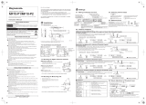
Connection diagram
1) Feedback contacts not connected: set 8rel.8 8trel.8 8 off.8
2) N connected: select 8Pr 18 , 8Pr 38 or 8Pr 58
3) Nc- or no-contacts can be connected, self-learning when switching on
4) Switch off of plant without recording an alarm, e.g. with contact of a ripple control receiver
5) Fuses only when line protection necessary, e.g. 3x16A

UFR1001E 12420-0751-00 Page
4
/ 8 www.ziehl.de
Program setup
The suitable program must be set on the CM-UFD.M21 in accordance with the application. If the
CM-UFD.M21 is sealed/locked (red LED lightning), sealing has to be deactivated first.
Pr
Connection
Threshold values
Voltage
*1
3 AC with N
Low voltage
1x overvoltage, 1x undervoltage
1x overfrequency, 1x underfrequency
10 min average value, 1x vector shift
230 V
2
3 AC w/o N
400 V
3
3 AC with N
Medium voltage
2x overvoltage, 2x undervoltage
2x overfrequency, 2x underfrequency
10 min average value, 1x vector shift
57.7 V
4
3 AC w/o N
100 V
5
3 AC with N
230V
6
3 AC w/o N
400V
* default setting
Adjustment process:
If present, remove seal (only authorised person)
Apply control supply voltage at A1-A2
Slightly lift the button cover and turn 180°
Actuate the small blue button by strong pressing on the button cover (LED starts flashing)
until the green LED is lightning.
Press button 1x Display 8Info.8
Press button 5x Display 8Pr 1.8
Set the program with the buttons
Press button 1x Display 8 no.8
Press button 1x Display 8 yes.8
Press button
Device resets and starts with the newly selected program
Hint: When changing programs, all parameters of the selected program are reset to “default settings“
(see table „Default settings“). Only change the parameters after having selected the correct
program.
Technical data
Rated control supply voltage U
s
: 24-240 V AC/DC, DC / 40-70 Hz, <5 VA
Tolerance -15…+10 %
Output relays: 2 c/o contacts
Max. switching voltage 400 V AC
Conventional thermal current I
th
6 A
Inrush current (at 10 % ED) 25 A max. 4 s / 50 A max. 1 s
Rated operational current I
e
(AC15) 230 V AC / 1.5 A
Fuse rating to achieve short-ciruit protection max. gG/gL 6 A
Mechanical lifetime 30 x 10
6
switching cycles
Electrical lifetime 1 x 10
6
switching cycles at AC12, 230 V, 6 A
Output voltage - transistor outputs Q1-Q5
Operational voltage V
Q
4.5-27 V DC
Max. current consumption Q1…Q5 20 mA / output
Input circuit - feedback contacts Y0 – Y1/2
No-load voltage at the control inputs 15-35 V DC
Feedback time section switch 0.5-99.0 s selectable
Subject to change without prior notice

UFR1001E 12420-0751-00 Page
5
/ 8 www.ziehl.de
Control chart
8Pr 18 3AC with N, acc. to VDE-AR-N 4105 8Pr 28 3AC w/o N, acc. to VDE-AR-N 4105
[ ] = Unit
Pressing buttons Up/Down
simultaneously, sets the
values to the smallest one.
Code-Reset = Press button Set 2 s
while applying control supply voltage.
(Pin = 504)
Error reports:
Err4 = Tolerance Master Slave
Err5 = internal regulation
Err6 = communication error
Err7 = return error K1/K2
Err8 = limit error high < low
Err9 = parameter error
Display mode
Configuration mode
Menu mode
1) 3AC+N = 300V

UFR1001E 12420-0751-00 Page
6
/ 8 www.ziehl.de
Default settings and firmware version
When changing programs, all parameters are reset to the default settings.
Menu
point
Parameter / Unit
Default settings
Users data
Low voltage
Medium voltage
3AC+N
230V
3AC
400V
3AC+N
57,7V
3AC
100V
3AC+N
230V
3AC
400V
Pr1 *
Pr2
Pr3
Pr4
Pr5
Pr6
U,,
u,, Alarm on/off
-
-
on
on
on
on
u,, Overvoltage
V
-
-
66.4
115
264
458
H,, Hysteresis
V
-
-
1.0
1.0
3.0
3.0
dal ON-delay
s
-
-
0.10
0.10
0.10
0.10
dof OFF-delay
s
-
-
60
60
60
60
U,
u, Alarm on/off
on
on
On
on
on
on
u, Overvoltage
V
264
458
62.3
108
249
430
H, Hysteresis
V
5.0
5.0
1.0
1.0
3.0
3.0
dal ON-delay
s
0.10
0.10
60.00
60.00
60.00
60.00
dof OFF-delay
s
60
60
60
60
60
60
UM
UM Alarm on/off
on
on
Off
Off
off
Off
UM Overvoltage
V
253
438
253
438
253
438
HM Hysteresis
V
3.0
3.0
3.0
3.0
3.0
3.0
dal ON-delay
s
0.10
0.10
0.10
0.10
0.10
0.10
dof OFF-delay
s
60
60
60
60
60
60
U_
u_ Alarm on/off
on
on
On
On
on
on
u_ Undervoltage
V
184
318
46.2
80.0
184
318
H_ Hysteresis
V
5.0
5.0
1.0
1.0
3.0
3.0
dal ON-delay
s
0.10
0.10
2.70
2.70
2.70
2.70
dof OFF-delay
s
60
60
60
60
60
60
U__
u__ Alarm on/off
-
-
Off
Off
off
Off
u__ Undervoltage
V
-
-
26.0
45.0
104
180
H__ Hysteresis
V
-
-
1.0
1.0
2.0
2.0
dal ON-delay
s
-
-
0.30
0.30
0.30
0.30
dof OFF-delay
s
-
-
60
60
60
60
F,,
F,, Alarm on/off
-
-
off
Off
off
Off
F,, Overfrequency
Hz
-
-
51.50
51.50
51.50
51.50
H,, Hysteresis
Hz
-
-
1.45
1.45
1.45
1.45
dal ON-delay
s
-
-
0.10
0.10
0.10
0.10
dof OFF-delay
s
-
-
60
60
60
60
F,
F, Alarm on/off
on
on
on
on
on
on
F, Overfrequency
Hz
51.50
51.50
51.50
51.50
51.50
51.50
H, Hysteresis
Hz
1.45
1.45
1.45
1.45
1.45
1.45
dal ON-delay
s
0.10
0.10
0.10
0.10
0.10
0.10
dof OFF-delay
s
60
60
60
60
60
60

UFR1001E 12420-0751-00 Page
7
/ 8 www.ziehl.de
Menu
point
Parameter / Unit
Default settings
Users data
Low voltage
Medium voltage
3AC+N
230V
3AC
400V
3AC+N
57,7V
3AC
100V
3AC+N
230V
3AC
400V
Pr1 *
Pr2
Pr3
Pr4
Pr5
Pr6
F_
F_ Alarm on/off
on
on
on
on
on
on
F_ Underfrequency
Hz
47.50
47.50
47.50
47.50
47.50
47.50
H_ Hysteresis
Hz
1.00
1.00
1.00
1.00
1.00
1.00
dal ON-delay
s
0.10
0.10
0.10
0.10
0.10
0.10
dof OFF-delay
s
60
60
60
60
60
60
F__
F__ Alarm on/off
-
-
off
off
off
off
F__ Underfrequency
Hz
-
-
47.50
47.50
47.50
47.50
H__ Hysteresis
Hz
-
-
1.00
1.00
1.00
1.00
dal ON-delay
s
-
-
0.10
0.10
0.10
0.10
dof OFF-delay
s
-
-
60
60
60
60
vsr
vsr Alarm on/off
off
off
off
off
off
off
vsr Vector shift
°
10.0
10.0
10.0
10.0
10.0
10.0
dof OFF-delay
s
3
3
3
3
3
3
dEon Suppression time
s
2
2
3
3
3
3
vsr Number of phases
3ph
3ph
3ph
3ph
3ph
3ph
rEL
trEL Switching time
Y1,Y2
s
5.0
5.0
off
off
off
off
ddi
ddi Display delay
s
0.5
0.5
0.5
0.5
0.5
0.5
dit Display duration
SCn
s
3.5
3.5
3.5
3.5
3.5
3.5
Si
U Voltage
V
230
400
57.7
100
230
400
F Frequency
Hz
50.00
50.00
50.00
50.00
50.00
50.00
vsr Vector shift
°
0.0
0.0
0.0
0.0
0.0
0.0
CodE
pin Pin code
504
504
504
504
504
504
Info
fnr Firmware version
0-00
0-00
0-00
0-00
0-00
0-00
snr Serial number
xxxxx
xxxxx
xxxxx
xxxxx
xxxxx
xxxxx
h Operating hours
h
xxxxx
xxxxx
xxxxx
xxxxx
xxxxx
xxxxx
err Error counter
xxx
xxx
xxx
xxx
xxx
xxx
Pr Program
1
2
3
4
5
6
* factory preset
Display of the program: 8Info8 8Pr 8 or when switching on
Display of the firmware version: 8Info8 8fnr 8
Protective functions, default settings according to VDE-AR-N 4105 section 6.5.2
Voltage increase protection U>> 8U, 8 1.15 Un 100 ms
Voltage increase protection U> 8UM 8 1.1 Un 100 ms
Voltage decrease protection U< 8U_ 8 0.8 Un 100 ms
Frequency increase protection f> 8f, 8 51.5 Hz 100 ms
Frequency decrease protection f< 8f_ 8 47.5 Hz 100 ms

UFR1001E 12420-0751-00 Page
8
/ 8 www.ziehl.de
Troubleshooting
Error
Cause
Remedy
8EEEE8 or 8-EEE8
appears in the display
Measured voltage,
frequency or the vector shift
is too large or too small
Consider the measuring range
8Err48
appears in the display
Too high internal
measurement deviation of
the two measuring channels
Perform a reset
interrupt the control supply voltage
for >5 s
8Err58
appears in the display
Error internal regulation
8Err68
appears in the display
Communication error
internal interface
8Err78 appears in
the display + LED d of
the faulty output
circuit is lightning
Error feedback contacts
Feedback contacts not connected
- set 8trel.8 8 off8
Feedback contacts connected
- check the correct connection
- Adjust the turn-on time of the section
switch under 8trel.8
- Perform a reset interrupt the
control supply voltage for >5 s
8Err88
appears in the display
Hysteresis error:
overlapping of the release
points
Upper threshold value must be higher
than the lower threshold value, check
the threshold values
8Err98
appears in the display
Configuration error
Reset to factory settings, see “Program
setup”
A time expires in the
display
If a OFF-delay 8dof 8 is
active, the time runs down
in the display (the shortest
one first)
Wait until the time is complete
(depending on the setting, several
times may elapse one after the other)
Device cannot be
configured / only the
threshold values can
be configured
Code lock / Sealing
activated
When having problems with the code
lock (Pin forgotten), the lock can be
deactivated and the pin can be reset to
504 , by pressing the button until
8Code8 / off8 is shown in the
display, while switching on the control
supply voltage
Implausible voltage
values
Pr selected with N, but N
not connected
Select Pr without N or connect N
8Loc 8
appears in the display
Sealing is active
See „Program setup“
8Code8
appears in the display
Code lock is active
See „Code lock“
/