Kenmore 153335851 User manual
- Category
- Water heaters & boilers
- Type
- User manual

0291319
SE_A/RS o:
Gas Water Heater
Owners Manual
FOR POTABLE WATER HEATING ONLY
NOT SUITABLE FOR SPACE HEATING
NOT FOR USE IN
MOBILE HOMES
MODEL NUMBERS:
153.335200 40 Gal. High Altitude
153.335250 40 Gal.
153.335251 40 Gal.
153.335302 30 Gal. High Altitude
153.335350 30 Gal.
153.335351 30 Gal.
153.335400 40 Gal. High Altitude
153.335450 40 Gal.
153.335451 40 Gal.
153.335502 50 Gal. High Altitude
153.335550 50 Gal.
153.335551 50 Gal.
153.335600 65 Gal. High Altitude
153.335650 65 Gal.
153.335651 65 Gal.
153.335750 50 Gal.
153.335751 50 Gal.
Save this Manual for Future Reference.
0
Z
-Do not store or use gasoline or other
flammable vapors affd liquids in the
vicinity of this or any other appliance.
-WHAT TO DO IF YOU SMELL GAS
• Do not try to light any appliance.
• Do not to°uch any electrical switch; do
not use any phone in your building.
• Immediately call your gas supplier
from a neigh_bor's phone. Follo'w the
gas supplierV's instrui:tions.
• if you can not reach your gas supplier,
call the fire department.
-Installation and service must be per-
formed by a qualified installer, service
agency or the gas supplier.
WARNING: If the information in these
instructions are not followed exactly, a
fire or explosion may result, causing prop-
erty damage, personal injury or dea]l_.
WARNING
READ THE GENERAL SAFETY SECTION
BEGINNING ON INSIDE COVER AND
THEN THIS ENTIRE MANUAL BEFORE
INSTALLING OR OPERATING THIS
WATER HEATER.
WARNING
Flammable vapors may be drawn by air
currents from other areas of the struc-
ture to this appliance.
WARNING
Improper installation, adjustment, alter-
ation, service or maintenance can cause
DEATH, SERIOUS BODILY INJURY, OR
PROPERTY DAMAGE. Refer to this manu-
al for assistance or consult the local Sears
Service Center or gas utility for further
information.
153.335850 65 Gal.
153.335851 65 Gal.
153.335951 40 Gal. L.P.
k2
• Installation • Operation • Repair Parts
For Your Safety ANODORANT,SADDEDTOTHECAS
USED BY THIS WATER HEATER

WARNING
Improper installation, adjustment, alteration, service or mainte-
nance can causeDEATH, SERIOUS BODILY INJURY OR PROP-
ERTY DAMAGE. Refer to this manual for assistanceor consult
your local SearsService Center for further information.
WARNING
At the time of manufacture thiswater heater was providedwith a
combination temperature-pressures relief valve certified by a
nationally recognized testing laboratory that maintains periodic
inspedion of produdion of listedequipment or materials,asmeet-
ing the requirementsfor Relief Valvesand Automatic Gas Shutoff
Devices for Hot Water Supply Systems,and the latest edition of
ANSI Z21.22 and the coderequirementsof ASME. If replaced,the
valvemust meet the requirementsof local codes,but not lessthan
a combination temperature and pressurerelief valve certified as
meeting the requirements for Relief Valves and Automatic Gas
ShutoffDevices for Hot Water SupplySystems,ANSI Z21.22 by a
nationally recognized testing laboratory that maintains periodic
inspectionofprodudion of listedequipment or materials. _
The valve must be marked with amaximum set pressurenot to
exceed the marked hydrostatic working pressure of the water
heater (150 Ibs:q./sin.) and a dischargecapacity not less.than the
water heater input rate as shown on the model rating plate.
(Electric heaters- watts divided by 1000 x 3415 equal BTU/Hr.
rate.)
Your local jurisdictional authority, while mandatingthe use of a
temperature-pressurerelief valve complyingwith ANSI Z21.22 and
ASME,may require a valvemodel different from the onefurnished
with the waterheater.
Compliance with suchlocal requirementsmust be satisfiedby-the
installeror end userof the water heater with a locally prescribed
temperature-pressurerelief valve installedin the designatedopen-
ingin thewater heater in placeof the factoryfurnishedvalve.
For safeoperation of the water heater,the relief valve mustnotbe
removedfrom it's designatedopeningor plugged.
The temperature-pressure reh'ef valve must be installed directly
into the fitting of the water heater designatedfor the relief valve.
Positionthe valve downward and provide tubing so that any dis-
charge will exit only within 6 in(_hesabove, or at any distance
below the structural"floor.Be certain that no contact ismade with
any live electricalpart. The dischargeopeningmustnot be blocked
or reducedin sizeunder anycircumstances.Excessivelength, over
15 feet, or useof more thantwo elbows can causerestridion and
reduce the dischargecapacityofthe valve.
No valve or other"obst'ructionis to be placed between the relief
valve and the tank. Do not connect tubing directly to discharge
drain unlessa 6" air gap is provided.Toprevent bodilyinjury,haz-
r ' ....
a d to life, or property-damage,the relief valve mustbe allowed to
dischargewater in quantitiesshould circumstancesdemand.If the
discharge pipe is not connected to a drain or other suitable
means,the water flow may causeproperty damage.
The Discharge Pipe:
--Must not Me smaller in size than the outlet pipe size of the
valve, or have any reducing couplingsor other restridions.
--Must not be plugged or blocked.
--Must be of material listed for hot water distribution.
--Must be installed so as to allow complete drainage of both
the temperature-pressure relief valve, and the discl_argepipe.
--Must terminate at an adequate drain.
--Must not have any valve between the relief valve and tank.
WARNING
A fire can start if combustiblematerialssuchasclothing, cleaning
materials, or flammable liquidsare placed againstor next to the
water heater.
WARNING
WATER HEATERSEQUIPPED FOR ONE TYPEGAS ONLY: This
water heater is quipped for one type gasonly.Checkthe model
ratingplate nearthe gascontrolvalvefor thecorred Eas.DO NOT
USE"IHIS WATERHEATERWITH ANY GAS OTHEI_ THAN THE
ONE SHOWN ON THE MODEL RATING PLATE.Failureto usethe
corred gascancauseproblemswhich can resultin DEATH,SERI-
OUS BODILY INJURY,OR PROPERTYDAMAGE. If you have any
questionsor doubtsconsultyourgassupplieror localutility.
WARNING
INSTALLATIONS IN AREAS WHERE FLAMMABLE LIQUIDS
(VAPORS)ARELIKELYTO BEPRESENTOR STORED(GARAGES,
STORAGE,AND UTILITY AREAS,ETC):Flammableliquids(suchas
gasoline,solvents,propane(LP)or butane, etc.), all of whichemit
flammable vapors, may be improperly stored or used in such
areas.The gaswater heater pilot light or main burner can ignite
suchvapors.The resultingflashbackand fire can causedeath or
seriousburnstoanyonein the area,aswell aspro_rty damage.
If installationin suchareasis your only option,then the installa-
tion mustbe accomplishedin a way that the pilot flame andmain
burner flame are elevatedfrom the floor at least 18 inches.While
thismay reducethe changesof flammablevaporsfrom afloor spill
being ignited, gasolineand other flammable substancesshould
never I_ storedor usedin the sameroom or area containinga gas
water heateror otheropen flameor sparkproducingappliance.
NOTE: Flammable vapors may be drawn by air (_urrentsfrom
other areasof thestructureto the appliance.
WARNING
HOTTER WATERCAN SCALD:Water heatersare intendedto pro-
duce hot water. Water heated to a temperaturewhich will satisfy
clothes washing, dish washing, and other sanitizing needs can
scaldand permanentlyinjure you upon contact.Somepeople are
more likely to be permanently injured by hot water than others.
Theseincludethe elderly,children, the infirm, or physically/men-
tally handicapped.If anyoneusinghot water in your home fits into
one of thesegroupsor if there is a local codeor statelaw requir-
ing a certain temperature water at the hot water tap, then you
must takespecialprecautions.In additionto usingthe lowestpos-
sibletemperaturesettingthat satisfiesyour hotwater needs,some
type of temperingdevice,suchas a mixingvalve, shouldhe used
at the hot water tapsusedby thesepeopleor at the water heater.
Mixing valvesare availableat plumbing supplyor hardwarestores.
Follow manufacturersinstructionsfor installation of the valves.
Before changingthe factory setting on the thermostat, read the
"Temperature Regulation"sectionin thismanual.
WARNING
BEFORELIGHTING [PROPANE (L.P.) GAS WATER HEATERS]:
Propane(LP.) gasisheavierthan air. Shouldtherebe a leak in the
system, the gaswill settle near the ground. Basements,crawl
spaces,skirtedareasunder mobile homes(evenwhenventilated),
closetsand areasbelow groundlevel will serveaspocketsfor the
accumulationof this as Before attemptingto light or relight the
g , • -- --_ . •
water heater'spilot or turningon a nearby electricallightswitch,
be absolutelysurethere isnoaccumulatedgasin the area.Search
for odor of gas by sniffingat _round level in the vicinity of the
appliance. If odor isdetected,_'ollow stepsindicatedat "For Your
Safety"on the coverpageof thismanualthenleavethe premises.
WARNING
Do not usethis applianceif any part of it hasbeen under water.
Immediately call a SearsServiceTechnicianto inspectthe appli.
ance and to replacethe gascontrol or any part of the burner sys-
tem which hasbeenunderwater.

WARNING
;This water heater must not be installed directly on carpeting.
Carpetin.gmust be protected by a metal or woodpanel beneath
the appliance extending b.eyondthe full width and depth of the
applianceby at least 3 inches (76.2mm) in any direction, or if the
appliance !sinstalled inan a!coveor closet,the entire floor must
be covered by the panel. Failure to heed this warning may result
in a fire hazard.
WARNING
A gaswater heater cannot operate properly without the correct
amount of air for combustion. Do notinstall in a confined area
such a closet, unlessyou provide air as shown in the "Locating
The New Water Heater" section.Never obstructthe flow of ven-
tilation air. If you have any doubtsor questionsat all, call your
gas company. Failure toprovide the proper amount of combus-
tion air can result in a fire or explosion and can cause DEATH,
. SERIOUS BODILY INJURY,OR PROPERTYDAMAGE.
WARNING
If this water heater will be usedin beauty shops,barber shops,
cleaningestablishments,or self-servicelaundrieswith dry clean-
"ing equlpment, it is imperative that the water heater or water
heaters be installed so that combustion and ventilation air be
taken from outside these areas. Refer to the "Locating The New
Water Heater" sectionof thismanual and alsothe latestedition of
the National Fuel Gas Code, ANSI Z223.1, also referred to as
NFPA54 for specificsprovided concerningair required.
WARNING
_VENTDAMPERS- Any vent damper,whether it isoperated ther-
mally or otherwise must be removed if its use inhibits proper
drafting ofthe water heater.
Thermally Operated Vent Dampers:Gas-fired water heaters hav-
ingthermal efficiency in excessof 80% may producea relatively
low flue gastemperature. Suchtemperatures may not be high
enough to properly open thermally operated vent dampers.This
would causespillageof flue gasesandmay causecarbon monox-
'ide poisoning.
Vent dampers must bear evidence of certification as complying
with the latest edition of American National Standard ANSI
Z21.68 (ANSI Z21.66 & 67, respectively,cover electrically and
mechanically actuated vent dampers). Before installationof any
vent damper, consult your local SearsService Center or the gas
utility for further information.
WARNING
1. The appliance and its individual shutoff valve mustbe discon-
nectedfrom the gassupplypiping systemduringany pressure
testingof thegas systemat test pressuresin excessof '/2pound
per square inch(3.5kPa).
2. The appliancemust be isolatedfrom the gassupplypiping sys-
tem by closin.gits individual manual..shutoffvarve during any
pressuretesting of the gassupply piping systemat test pres-
suresequal or lessthan _2pound per squareinch (3.5kPa).
WARNING
_!Sootbuild-upindicatesa problemthat requirescorrection before
further use. Turn "OFF" gasto water heater and leave "OFF"
until repairsare made, becausefailure to correct the causeofthe
Sootingcan result in a fire or explosion causing DEATH, SERI-
OUS BODILY INJURY,OR PROPERTYDAMAGE.
WARNING
The water heater with draft hood installed must be properly
vented to a chimney which terminates outdoors.Never operate
the water heater unlessit isvented to the outdoorsand hasade-
quate air supplyto avoid risksof improper operation, explosion
or asphyxiateon.
WARNING
Obstructed or deteriorated vent systems may presenta serious
health riskor asphyxiation.
WARNING
Chemicalvapor corrosionofthe flue and vent systemmay occur
if air for combustioncontainscertain chemical val_rs. Spraycan
propellants, cleaning solvents, refrigerator and air conditioner
refrigerants, swimming pool chem|cals, calcium and sodium
chloride, waxes, bleach,and processchemicalsare typical com-
poundswhich are potentiallycorrosive.
WARNING
Minimum clearancesbetween the water heater and combustible
constructionare 1" at the sidesand rear, 4" at the front, and 6"
from the vent pipe. Clearance from the top of the jacket is 18"
on most models. Note that a lesser dimensionmay be a!lowed
on somemodels.Refer to the label on the waterheater adjacent
to the gascontrol valvefor all clearances.
WARNING
HYDROGEN GAS: Hydrogengascan be producedin a hot water
systemthat hasnot beenusedfor a long period of time (general-
ly two weeks or more). Hydrogen gas ts_ extremely flammable
and explosive.To prevent the poss_ility of injury under these
conditions,we recommendthe hot water faucetbe opened for
several minutesat the kitchen sink before any electrfcal appli-
ances which are connected to the hot water systemare used
(such as a dishwasheror washing machine). If hydrogengas is
present,there will probably be an unusualsoundsim]lar to a!r
escaping through the pipe as the hot water faucet is opened.
There mustbe no smokingor open flame near the faucet at the
time it isopen.
WARNING
INSULATING JACKETS:When installingan externalwater heater
insulationjacketon agaswater heater:
a. DO NOT cover the temperature-pressurerelief valve.
b. DO NOT put insulationover any part of the top of the gas
water heater.
c. DO NOT put insulationover the gascontrol valve or gascon-
trol valve/burner cover,or any accessareastothe burner.
d. DO NOT let insulation around the gaswater heater to get
within 8 inchesof the floor (air must get to the burner).
e. DO NOT cover or remove operating instructions,and safety
related warning labels and materials affixed to the water
heater.
Failure to heed this will result in the possibility of a fire or
explosion.
WARNING
Do not usethis appliance if any part of it hasbeenunder water.
Immediately call a SearsServiceTechmclan to inspectthe appli-
ance andto replace the gascontrol or anypart of the burner sys-
tem which hasbeen underwater.
CAUTION
WATER HEATERSEVENTUALLYLEAK: Installation of the water
heater mustbe accomplishedin suchamanner that if the tank or
any connectionsshould leak, the flow of water will not cause
damageto the structure.When suchlocationscannot be avoid.
ed, a suitable drain pan should be installed under the water
heater. Drain pansare available at your local Searsstore, Sucha
drain pan mustbe not greater than 11/_inches deepthave a mini-
mum lengthandwidth of at least 2 inchesgreaterthan the water
heater dimensionsand must be .pipedto an adequate drain. The
pan must not restrict combust,on air flow. Under no circum-
stancesis the manufacturer or Searsto be held liable for any
water damagein connectionwith this water heater.

General Safety................................................................................................................................._-_
Table of Contents ...........................................................................................................................4
Introduction ..........................................................................................................................................5
SPepeCifications.......................................................................................................................................5
aring for the New Installation ...................................................._.................s
Materiafs and Basic Tools Needed ............._............._...................................,........6
Materials Needed .................................................................................................................................................. 6
Basic Tools ............................................................................................................................................................ 6
Removing the Old Water Heater. ............................................................................7
Locating the New Water Heater ...........................................................................8-9
Facts to Consider About Location .......................................................................................................................... 8
Combustion Air and Ventilation for Appliances Located in Unconfined Spaces ..................................................... 9
Combustion Air and Ventilation for Appliances Located in Confined Spaces ......................................................... 9
Installing the New Water Heater .............,.......................................................lo-14
Water Piping .......................................................................................................... .............................................. 10
Temperature-Pressure Relief Valve ....................................................................................................................... 11
Filling the Water Heater..: .................................................................................................................................... 12
Venting ................................................................................................................................................................ 12
Gas Piping ................................................................................................................................................... •........ 13
Installation Checklist ........................................................................................................................................... 14
Lighting ..................................................................................................................................................._s-_6
Temperature Regulation .....................................................................................................lz
For Your Information ........................................................................................................;_a-19
Start Up Conditions ............................................................................................................................................. I 8
Condensation .................................................................................................................................... "................ 18
Smoke/Odor ...................................................................................................................................................... 18
Thermal Expansion ............................................................................................................................................. 18
Strange Sounds .................................................................................................................................................. 18
Operational Conditions ......................... . .................... .................................................................................... 18-19
Smelly Water ..................................... _.......................................................................................................... 18-19
"Air" In Hot Water Faucets ................................................................................................................................ 19
High Temperature Shut Off System .................................................................................................................... 19
Not Enough or No Hot Water ............................................................................................................................ 19
Water Is Too Hot ........................... i.................................................................... ................................................ 19
Periodic Maintenance .......................................................................................................2o-2_
Venting System Inspection ................................................................................................................................... 20
Burner Inspection ................................................................................................................................................ 20
Burner Cleaning .................................................................................................................................................. 20
Propane (L.P.) Gas Control Valve & Burner Assembly Replacement Information .................................................. 20
Housekeeping ........................................................................................................... . ......................................... 20
Temperature-Pressure Relief Valve Operation ...................................................................................................... 21
Tank Sediment Cleaning ................. •..................................................................................................................... 21
Draining .............................................................................................................................................................. 21
Drain Valve Washer Replacement .............................................................................. _......................................... 21
Service ................................................................................................................................................................ 21
Leakage Checkpoints ...............................................................................................................22
Repair Parts..................................................................................................................................... 24-31
IAI ._L..
vvarramv ...................................................................................................................................................
F
32
About Your"!warranty .............. ................................. ,........................................................................................... 32
Sears Installation Policy ....................................................................................................................................... 32
Sears Installation Warranty ................................................................... .'.............................................................. 32

-""/hanK You for purchasing a Sears water heater.
_roDerly installed and maintained, it should give you years of
rouble free service. If you should decide that you want the new
rater heater professionally installed by Searscall the local Sears
;erviceCenter or any Sears store. They will arrange for prompt,
luality installation by Searsauthorized contractors.
_bbreviations Found In This Instruction Manual
A.G.A. - American Gas Association
,.N.S.I. - American National Standards Institute
J.F.P.A.- National Fire Prevention Association
WARNING
This gas-fired water heater is design certified by the
American Gas Association Laboratories under
American National Standards for Gas Water Heaters.
The installation must conform with this manual, Local
Codes and with the latest edition of the National Fuel
Gas Code, ANSI Z223.1.
This publication is available from your local govern-
ment or public library, gas company, or by writing
NFPA, Batterymarch Park, Quincy, MA 02269.
RECOVERY DIMENSIONS IN INCHES
TANK TYPE I I _._l_- tJAL_. MINIMUM
MODEL NUMBER CAPACITY OF B.T.U. PERHOUR VENT HEIGHT TO
IN GALLONS GAS RATE @90°F RISE PIPE DIAMETER JACKET TOP
153.335200 40 NATURAL 35,000 35.8 3" or 4'I 20" ..... 47'/2"
153.335250 40 NATURAL 35 O00 35.8 3" or 4" 20" 47'/2"
153.335251 40 NATURAL 35,000 35.8 3" or 4" 20" 471/2''
153.335302 30 NATURAL 40,000 40.9 3" or 4" -16" 57'/2"
153.335350 30 NATURAL 40,000 40.9 3" or 4" 16" 57'/2"
153.335351 30 NATURAL 40.000 40.9 3" or 4" 16" 57'/,."
153.335400 40 NATURAL 40,000 40.9 3" or 4" 18" 58'/4"
153.335450 40 NATURAL 40,000 40.9 3" or 4" 18" 581/4''
153.335451 40 NATURAL 40,000 40.9 3" or 4" 18" 58'/4"
153.335502 50 NATURAL 40,000 40.9 3" or 4" 20'I 58"
153.335550 50 NATURAL 40,000 40.9 3" or 4" 20" 58"
153.335551 50 NATURAL 40,000 40.9 3" or 4" 20" 58"
153.335600 65 NATURAL 40,000 40.9 3" or 4" 22" 59'/2"
, ,, . , ....
153.335650 65 NATURAL 40,000 40.9 3" or 4" 22" 59'/2"
153.335651 65 NATURAL 40,000 40.9 3I' or 4" "22" 591/2''
153.335750 50 NATURAL 52,500 53.7 4" 20" 583/4''
153.335751 50 NATURAL 52,500 53.7 4" 20" 58¥4"
153.335850 65 NATURAL 50,000 51.2 4" 22" 591/2'i
153.335851 65 NATURAL 50,000 51.2 4" 22" "' 591/2"
153.335951 40 PROPANE 40,000 40.9 3" or 4" 18" ",58'/4"
.... [
Readthe"GeneralSafety"section,pages2 and 3of this manual
firstandthentheentiremanualcarefully.If you don'tfollow the
safetyrules,thewater heaterwill notoperateproperly.Itcould
causeDEATH,SERIOUSBODILYINJURYAND/OR PROPERTY
DAMAGE.
Thismanualcontainsinstructionsfor the installation,operation,
and maintenanceof the gas-firedwater heater.It alsocontains
warningsthrough out the manualthat ou mustread and be
a - Y
wareof. All warningsand all instructionsare essentialto the
properoperationof the water heaterand yoursafety.Sincewe
cannotput everythingon thefirstfewpages,READTHEENTIRE
MANUALBEFOREATTEMPTINGTO INSTALLOR OPERATE
THEWATERHEATER.
Theinstallationmustconformwith theinstructionsin thismanual;
gascompanyrules;and LocalCodes,or in theabsenceof Local
Codes,withthelatesteditionoftheNationalFuelGascode,ANSI
Z223.1,alsoreferredtoasNFPA54.Thispublicationisavailable
from yourlocalgovernmentor public libraryor gascompanyor
bywriting NFPA,BatterymarchPark,Quincy,MA02269.
3. If after readingthis manual you haveany questionsor do not
understandanyportionof the instructions,call theSearsService
Center.
4. Carefullyplan theplacewhere you aregoing to put the water
heater.Correctcombustion,ventaction,andventpipeinstallation
are very important in preventing deathfrom possiblecarbon
monoxidepoisoningandfires.
Examinethelocationtoensurethewaterheatercomplieswith the
"LocatingtheNewWaterHeater'sectionin thismanual.
5. ForCalifornia installation this water heatermustbe braced,
anchored,or strappedtoavoidfallingor movingduringan earth-
quake. See instructions for correct installation procedures.
Instructionsmaybeobtainedfrom yourlocaldealer,wholesaler,
publicutilities or CaliforniaOffice of theStateArchitect,400 P
Street,Sacramento,CA95814.

Materials Needed
To simplify the installation Sears has available the installa-
tion parts shown below. You may or may not need all of
these materials, depending on your type of installation.
: i i
i
WATER HEATER
INSTALLATION KIT WITH
FLEXIBLE CONNECTORS FOR
3/4" GALVANIZED OR
1/2"COPPER PLUMBING
COMPRESSION COUPLINGS
FOR CONNECTING TO
COPPER PLUMBING WITH-
OUT SWEAT SOLDERING
VENT ELBOW
EXPANSION TANKS FOR
THERMAL EXPANSION
CONDITIONS AVAILABLE
IN 2 GALLON AND 5
GALLON CAPACITY
THROUGH LOCAL SEARS
SERVICE CENTERES
VENT EXTENSION
WM_
FLEXIBLE WATER
HEATER GAS CON-
NECTOR WITH
FITTINGS
Wi_ P,4attr
Heat Tr_$
WATER HEATER HEAT TRAPS
HELP REDUCE HEAT LOSS DUE
TO THERMAL SYPHONING
WATER HEATER STAND 24"x24"x18"
FOR USE WITH WATER HEATERS INSTALLED
IN RESIDENTIAL GARAGES HAVING A DIAM-
ETER 24" OR LESS AND A RATED CAPACITY
75 GALLONS OR LESS
DRAIN PANS
AVAILABLE IN 20" DIAMETER FOR
WATER HEATERS HAVING A DIAMETER 18"
OR LESS AND AVAILABLE IN 28" DIAMETER
FOR WATER HEATERS HAVING A DIAMETER
26" OR LESS
Basic Tools
You may or may not need all of these tools, depending on
your type of installation. These tools can be purchased at
your local Searsstore.
Pipe Wrenches (2) 14"
Screwdriver
Tin Snips
6 Foot Tape of Folding Rule
Garden Hose
Drill
Pipe dope or Teflon Tape
GARDEN HOSE 6 FOOT TAPE
_REWDRIVER
PIPE
WRENCH
PHILLIPS SCREWDRIVER.s..._
f(__ TIN SNIPS
ROLL OF TEFLON TAPE
(USE ONLY ON WATER
CONNECTIONS)
PIPE DOPE (SQUEEZE TUBE)
(USE FOR WATER AND GAS CONNECTIONS)
ADDITIONAL TOOLS NEEDED
WHEN SWEAT SOLDERING
Tubing Cutters or Hacksaw
Propane Torch
SoffSolder
Solder Flux
Emery_Cloth
Wire Brushes
HACKSAW
3/4" WIRE BRUSH
_BRUSH
ROLL OF LEAD FREE
SOFT SOLDER
ROLL OF EMERY
CLOTH
SOLDER FLUX
\
1
PROPANE TORCH
TUBING C(JTI'ER

Turn"OFF" the gassupply to the water heater.
WARNING
If the main gas line shutoff serving all
gasappliancesis used, also shut "6FF"
{he _[asat each appliance. Leaveall gas
appliances shut _'OFF" until the water
heater installation
Q Turn "OFF" the water to the water
heater. Some installations require
that the water be turned off to the
entire house.
®
Check again to make sure the gas
supply is "OFF" to the water heater.
Then disconnect the gas supply con-
nection from the gas control valve.
Q Attach a hose to the water heater
drain valve and put the other end in
a floor drain or outdoors. Open the
water heater drain valve. Open a
nearby hot water faucet which will
relievepressure in the water heater
and speed draining.
®
®
®
Q Disconnect the vent from the draft hood
pipe
where they connect to the water heater. In most
installations the vent pipe can be lifted off after
any screw or other attached devices are removed.
Dispose of the draft hood. The new water heater
has the draft hood which must be used for proper
operation.
G a. lf you have copper piping to the
water heater, the two copper water
pipes can be cut with a hacksaw
approximately four inches away
from where they connect to the
water heater. This will avoid cutting
off the pipes too short. Additional
cuts can be made later if necessary.
Disconnect the temperature-pres-
O sure relief valve drain line. When
the water heater is drained, discon-
nect the hose from the drain valve.
Close the drain valve. The water
heater is now completely discon-
nected and ready to be removed.
If you have galvanized pipe to the
water heater, loosen the two galva-
nized pipes with a pipe wrench at
the union in each line. Also dis-
connect the piping remaining to
the water heater. These pieces
should be saved since they may be
needed when reconnecting the
new water heater. Disconnect the
temperature-pressure relief valve
drain line. When the water heater
is drained, disconnect the hose
from the drain valve. Close the
drain valve. The water heater is
now completely disconnected and
ready to be removed.
iTh WARNING
e water passin£ out of the drain valve may be
extremely hot 1_oavoid being scalded, make
sure all connec'tionsare tight and that the water
ow isdirected away from any person.
CAUTION
Mineral buildup or ._edlmentmay haye accumulated
in the old water heater. This causes the water heater
to be much heavier than normal and this residue, if
spilled out, could cause stalnlng.

Facts to Consider About the
Location
You should carefully choose an indoor location for the
new water heater, because the placement is a very impor-
tant consideration for the safety of the occupants in the
building and for the most economical use of the appli-
ance. Thiswater heater is not for use in mobile homes or
outdoor installation.
Whether replacing an old water heater or putting the
water heater in a new location, the following critical
points must be observed.
I. The location selected should be indoors as close as
practical to the gas vent or chimney to which the
water heater vent is going to be connected, and as
centralized with the water piping system as possible.
The water heater, as all water heaters, will eventually
leak. Do not install without adequate drainage provi-
sions where water flow will cause damage.
WARNING
Propellants of aerosol sprays and volatile compounds,
(cleaners, chlorine based chemicals, refrigerants, etc.) in
addition to being highly flammable in many cases, will
also change to corroslve hydrochloric acid when exposed
to the combustion products ot the water heater. The
results can be hazardous, and also cause product failure.
2. The location selection must provide adequate clearances
for servicing and proper operation of the water heater.
WARNING
This water heater must not be installed directly on carpeting.
Zarpeting must beprotected by a metal or wood panel beneath
he applianceextending beyond the full width and depth of the
ippliance by at least 3 inches(76.2mm) in any direction, or if
he applianceis installed in an alcoveor closet, the entire floor
nust becovered by the panel. Failureto heedthis warningmay
'esultin afire hazard.
CAUTION
WATER HEATERS EVENTUALLY LEAK: Installation of the
water heater must be accomplished in such a manner that if
the tank or any connections should leak, the flow of water
will not cause damage to the structure. When such loca-
tions cannot be avoided, a suitable drain pan should be
installed under the water heater. Drain pans are available at
your local Sears store. Such a drain pan must be not greater
than 1'/2 inches deep, have a minimum length and width of
at least 2 inches greater than the water heater dimensions
and must be piped to an adequate drain. The pan must not
restrict combustion air flow. Under no circumstances is the
manufacturer or Sears to be held liable for any water dam-
age in connection with this water heater.
WARNING
INSTALLATIONS IN AREAS WHERE FLAMMABLE LIQ-
UIDS (VAPORS) ARE LIKELY TO BE PRESENT OR
STORED (GARAGES, STORAGE AND UTILITY AREAS,
ETC): Flammable liquids (such as gasoline, solvents,
propane (LP) or butane, etc.) or other substances (such
as adhesives, etc.), all of which emit flammable vapors,
may be imiprroperly, stored, or used. in such areas: The.
gas water heater pdot hght or mare burner can ign,te
such vapors. The resulting flashback and fire can cause
death or serious burns to anyone in the area, as well as
ropertv damalze.
installation I_nsuch areas is your only option, then
the installation must be accomplished in a way that the
pilot flame and main burner flame are elevated from
the floor at least 18 inches. While this may reduce the
changes of flammable vapors from a floor spill being
ignited, gasoline and other flammable substances
should never be stored or used in the same room or
area containing a gas water heater or other open flame
or spark produi:ingappliance.
Also, the water heater; must be located and/or protect-
ed so it is not subject to physical damage by a moving
vehicle.
NOTE: Flammable vapors may be drawn by air currents
from other areas of the structure to the appliance.
WARNING
Minimum clearances between the water heater and com-
bustible construction are 1" at the sides and rear, 4" at the
front, and 6" from the vent pipe. Clearance from the top of the
jacket is18" on most models.Notethat a lesserdimensionmay
be allowed on some models. Referto the label on the water
heater adjacent to the gascontrol valveon all clearances.
12" MAX.
-
f
VENTILATION
AIR O
OPENINGS
6" MI"N.
FRONT VIEW
OF DOOR
I_ MIN. 4" MIN.
TOP VIEW
OF CLOSET TOP VIEW I" MIN.
WffHOUT DOOR OF CLOSET
_" MAX. WITH DOOR
I Ii3'--;-
I ^lRoucr IIMJN.
AIR DUCT
WARNING
A water heater cannot properly without the cor-
gas operate
rect amount of air for combustion.Do notinstall in a confined
l area such as a closet, unless you provide air as shown in
Figures1-5. Never obstruct the flow of ventilation air. If you
have any doubtsor questionsat all, call your gascompany or
SearsService Center. Failure to provide the proper amount of
combustion air can result in a fire or explosion and can cause
DEATH, SERIOUS BODILY INJURY,OR PROPERTYDAMAGE.
WARNING
If this water heater will be usedin beauty shops,barber shops,
cleanin_establishments,or self-servicelaundries with dry clean-
ing equipment, it is imperative that the water heater or water
heatersbe installed so that combustionand ventilation air be
taken from outsidetheseareas.Refer to the "LocatingThe New
Water Heater" sectionof thismanual andalsothe latest edition
of the National FuelGasCode, ANSI Z223.1, alsoreferredto as
NFPA54 for specificsprovidedconcerningair required.

Combustion Air and Ventilation
for Appliances Located in
UnconfinedSpaces
UnconfinedSpaceisa spacewhose volume isnot lessthan 50
cubicfeet.per 1,000 .B.tu.perhourof theaggregate inputrating
ofall appliancesinstalledinthat space.Roomscommunicating
directlywith the space in which the appliances are installed,
through openingsnot furnished with doors, are considereda
partofthe unconfinedspace
Inunconfinedspacesin buildings, infiltrationmay be adequate
toprovide air for combustion,ventilation and dilution of flue
gases.However, in buildings of tight construction(forexample,
weatherstripping,heavily insulated,caulked, vapor barrier,
etc.),additional air may needto be provided usingthe methods
described in Combustion Air and Ventilation for Appliances
LocatedinConfined Spaces,b.
Combustion Air and Ventilation
for Appliances Located in
Confined Spaces
Confined Spaceis a spacewhose volume is lessthan 50 cubic
feet per 1,000 Btu per hour of the aggregateinput rating of all
appliancesinstalled in that space.
a.ALLAIRFROMINSIDE BUILDINGS:
(SeePage8 Figure1,and Figure2 below)
The confined space shall be provided with two permanent
openingscommunicating directly with an additional room(s)
of sufficient volume so that the combined volume of all
spacesmeetsthe criteria for an unconfined space.Thetotal
input of all gasutilization equipment installed in the com-
bined space s.hallbe considered in making th s determina-
tion. Eachopening shall have a minimum free area of one
squareinch per 1,000 BTU per hour of the total input rating
of all gas utilization equipment in the confined spade, but
not less than 100 square inches. One opening shall com-
mence within 12 inches of the top and one commencing
within 12 inchesof the bottom of the enclosure.
,-_i..:,::. i..
b. ALL,AIRFROM OUTDOORS: (seeFigures3-5)
The confined space shall be provided with two perma-
nent openings, one commencing within 12 inches of the
top and Onecommencing within 12 inches from the bot-
tom of the enclosure. The openings shall communicate
directly, or by ducts, with the outdoors or spaces(crawl or
attic)that freely communicate with the outdoors.
_qrulloH LOUW_
1. When directly communicating with the outdoors, each
opening shall have a minimum free area of 1 square inch
per 4,000 BTU per hour of total input rating of all equip-
ment in the enclosure. (SeeFigure3.)
2. When communicating with the outdoors through vertical
ducts, each opening shall have a minimum free area of 1
square inch per 4,000 BTU per hour of total input rating
of all equipment in the enclosure. (SeeFigure4.)
CHIMNEY OR GAS VENT
VENTUL.TION LOUVERS
AIR OUTLET
WATER HEATER
FURNACE
INLET AIR DUCT
I l (e_ 1' abo_ _c_)
Figure4
3. When communicating with the outdoors through horizon-
tal ducts, each opening shall have a minimum free area of
1 square inch per 2,000 BTU per hour of total input rating
of all equipment in the enclosure. (SeeFigure5.)
I Figure 5 [
4.
,
,
=_
_-.: R
When ducts are used, they shall be of the samecross-sec-
tional area as the free area of the openings to which they
connect. The minimum short side dimension of rectangular
air ducts shall not be lessthan 3 inches. (SeeFigure5.)
Louversand Grilles:In calculating free area,consideration
shall be given to the blocking effect of louvers, grilles or
screens protecting openings. Screens used shal| not be
smaller than 1/4inclhmesh. If the free area througha design
of louver or grille is known, it should be usedin calculat-
ing the size opening required to provide the freearea spec-
ified. If the design and free area is not known, it may be
assumedthat wood louvers will be 20-25 percent freearea
and metal louvers and grilles will have 60-75 percent free
area.Louversand grilles shall be fixed in the open position
or interlocked with the equipment sothat they are opened
automatically during equipment operation.
Special Conditions Created by Mechanical Exhaustingor
Fireplaces:Operation of exhaust fans, ventilation systems,
clothes dryers or fireplaces may create conditions requiring
special attention to avoid unsatisfactory operation of
installed gasutilization equipment.

Wate Piping,
WARNING
HoI"rER WATERCAN SCALD:Water heatersare intendedto
producehot water. Water heatedto a teml_rature which
will satisfyclothes washing,dish washing,andother sanitiz-
ing needscan scaldand permanentlyinjure you upon con-
tact.Somel_.ple are morelikelytobe permanentlyinjured
by hotwaterthano!hers.Theseincludethe elderly,_ildren,
the infirm, or physically/mentallyhandicapped.If anyone
usinghot waterin yourhomefitsInto oneofthesegroupsor
if there isa localcodeor statelaw requiringa certaintern-
perature waterat thehot watertap, then you musttakespe-
cial precautions,in additionto usingthe lowestpossibletem-
perature settin_ that satisfiesyour hot water needs,some
type.of tempenngdevice,suchasa mixingvalve;shouldbe
usedat the hot water tapsusedby.thesep_.pie or at the
water heater.Mixingvalvesare avadableat plumbing supply
or hardware stores.Follow manufacturers instructionsfor
installationofthe valves.Beforechangingthe factorysetting
on the thermostat,read the "Temperature Regulation"sec-
tionin thismanual.
This water heater shall not be connected to any heating
systems or component(s) used with a non-potable water
heating appliance.
If a water heater is installed in a closed water supply sys-
tem; such as one having a back-flow preventer, check
valve, water meter with a check valve, etc.., in the cold
water supply; means shall be provided to control thermal
expansion. Contact the local utility or local Sears Service
Center on how to control this situation.
NOTE: To protect against untimely corrosion of hot and
cold wate_fittings, it is strongly recommended that di-
electric unions or couplings I_e installed on this water
heater when connectedto copper pipe.
The illustration shows the attachment of the water piping
to the water heater. The water heater is equipped with 3/4
inch water connections.
NOTE: If using copper tubing, solder tubing to an
adapter before attac]_ingthe adaptor to the cola water
inlet connection. Do not solder the cold water supply
line directly to the cold water inlet. It will harm the iJip
tube and damage the tank.
1. Look at the top cover of the water heater. The water
outlet is marked hot. Put two or three turns of teflon
tape around the threaded end of the threaded-to-sweat
coupling and around both ends of the 3/4"threaded nip-
ple. Using flexible connectors, connect the hot water
pipe to the hot water outlet on the water heater.
2. Look at the top cover of the water heater. The cold
water inlet is marked cold. Put two or three turns of
teflon tape around the threaded end of the threaded-
to-sweat coupling and around both ends of the 3/4"
threaded nipple. Using flexible connectors, connect
the cold water pipe to .thecold water inlet of the water
heater.
NOTE: This water heater is super insulated to mini-
mize heat loss from the tank. Further reduction in
heat loss can be accomplished by insulatingthe hot
water linesfrom the water heater.
INSTALLATION COMPLETED USING
SEARS INSTALLATION KIT
HOT OUTLET
TO HOUSE
THREADED TO
SWEAT COUPLING
FLEXIBLEWATER
ECTORS
SHUTOFF
VALVE
COLD INLET
WATER LINE
3/4" THREADED
COUPLING
THREADED TO
COUPLING
10
t_l _ TEMPERATURE-
i PRESSURERELIEF
VALVE
_ DISCHARGE PIPE
(Do not cap
or plug)
:LOOR DRAIN

Temperature-PressureRelief Valve
WARNING
At the time of manufacture this water heater was provided
with a combination temperature-pressures relief valve certi-
fied by a nationally recognized testing laboratory that main-
tains periodic inspection of production of listed equipment
or materials, as meeting the requirements for Relief Valves
and Automatic Gas Shutoff Devices for Hot Water Supply
Systems,and the latest eoidon of ANSI Z21.22 and the code
requtrements of ASME. If replaced, the valve must meet the
requirementsof local codes, but not lessthan a combination
temperature and pressure relief valve certified as meeting
the requirements for Relief Valves and Automatic Gas
Shutoff Devices for Hot Water SupplySystems,ANSI Z21.22
by a nationally recognized testing laborato_ that maintains
periodic inspection of production of listed equipment or
materials.
The valve must be marked with a maximum set pressurenot
to exceed the marked hydrostatic working pressure of the
water heater (150 Ibs./sq. in.) and a discharge cai_city not
lessthan the water heater input rate as shown on the model
rating plate. (Electric heaters - watts divided by 1000 x 3415
equa| BTU/Hr. rate.)
Your local jurisdictional authority, while mandating the use
of a temperature-pressure relief valve complyingwith ANSI
Z21.22 and ASME, may require a valve moc'leld_erent from
the one furnished with the water heater.
Compliance with such local requirements must be satisfied
by the installer or end userof the water heater with a locally
prescribed temperature-pressure relief valve installed in the
€leslgnated opening in the water heater in place of the facto-
ry furnished valve.
For safe operation of the water heater, the relief valve must
notbe removed from it's designatedopening or plugged.
The temperature-pressure relief valve must be installed
directly into the fittin_of the water heater designated for the
relief valve. Positiont_e valve downward and provide tubing
sothat any dischargewill exit only within 6 inches above, or
at any distance below the structural floor. Be certain that no
contact is made with any live electrical part. The discharge
opening must not be blocked or reduced in size under any
circumstances. Excessivelength, over 15 feet_or useof more
than two elbows can cause restriction and reduce the
dischargecapacity of the valve.
No valve or other obstruction is to be placed between the
relief valve and the tank. Do not connect tubing directly to
discharge drain unless a 6" air gap is provided. To prevent
bodily injury, hazard to life, or oroperty damage, the relief
valve must be allowed to discharge water in quantities
should circumstances demand. If the discharge pnpe is not
connected to a drain or other suitable means, t-hewater flow
may causeproperty damage.
The Discharlze Pipe: . _
'--Must not Ee smaller in size than the outlet pipe size of the
valve, or have any reducing couplingsor other restriction.
---Must not be plumedor blocked.
_ust be of mate_]'al listedfor hot water distribution.
_ust be installed so asto allow complete drainageof both
the temperature-pressure relief valve, and the discharge
". . ..
._-_!! tner_nl_;va_eaatyana_vd;bqe_edr_e relief valve and tank.
11
WARNING
The temperature-pressure relief valve must be manual-
ly operated at least once a year. Caution should be
taken to ensure that (1) no one is in front of or around
the outlet of the temperature-pressure relief valve dis-
charge line, and (2) the water manually dischargedwill
not cause any bodily injury or property damage
becausethe water may beextremely hot.
If after manually operating the valve, it fails to com-
pletely reset and continues to release water, immedi-
ately closethe coldwater inlet to the water heater, fol-
low the draining instructions, and replace the tempera-
ture-pressurerelief valve with a new one.
..,_q
HOT
SHUTOFF COLD
VALVE
JRE-PRESSURE
RELIEFVALVE
[]
(Do not cap or plug)
6" AIR GAP
FLOOR DRAIN
RELIEFVALVEOPENING
ATTHETIMEOFMANUFACTURE,THISWATERHEATERWASPROVIDED
WITHACOMBINATIONTEMPERATURE-PRESSURERELIEFVALVELISTED
ASCOMPLYINGWITHTHESTANDARDFORRELIEFVALVESANDAUTO-
MATICGASSHUTOFFDEVICESFORHOTWATERSUPPLYSYSTEMS,
ANSIZ21.22.FOR SAFEOPERATIONOFTHE WATERHEATER,THE
RELIEFVALVEMUSTNOTBEREMOVEDFROMITSDESIGNATEDPOINT
OFINSTALLATIONORPLUGGED.
YOURLOCALJURISDICTIONALAUTHORITY,WHILEMANDATINGTHEUSE
OFA TEMPERATURE-PRESSURERELIEFVALVECOMPLYINGWITHANSI
Z21.22ANDASME,MAYREQUIREA VALVEMODELDIFFERENTFROM
THEONEFURNISHEDWITHTHEWATERHEATER.
COMPLIANCEWITHSUCHLOCALREQUIREMENTSMUSTBESATISFIED
BYTHEINSTALLERORENDUSEROF THEWATERHEATERWITHA
LOCALLYPRESCRIBEDTEMPERATURE-PRESSURERELIEFVALVE
INSTALLEDINTHEDESIGNATEDOPENINGINTHEWATERHEATER.
SEEMANUALHEADING--"TEMPERATURE-PRESSURERELIEFVALVES"
FORINSTALLATIONANDMAINTENANCEOF RELIEFVALVE,DISCHARGE
LINEANDOTHERSAFETYPRECAUTIONS.

Filling the Water Heater
CAUTION
Never usethis water heater unlessit is completely filled
with water. To prevent damageto the tank, the tank must
be filled with water. Water mustflow from the hot water
faucet before turning "ON" gasto the water heater.
Tofill the water heaterwith water:
1. Close the water heater drain valve by turning the han-
dle to the right (clockwise). The drain valve is on the
lower frontof thewater heater.
2. Open the cold watersupply valve to thewater heater.
NOTE: The cold water supply valve must be left open
when the water heater is|rl use.
3. To insure complete fillin_ of the tank, allow air to exit
by opening the nearesthot water faucet. Allow water
to run unti/a constantflow isobtained. Thiswill let air
out of the water heaterand the piping.
4. Check all new waterpipingfor leaks. Repairasneeded.
Venting
WARNING
VENT DAMPERS- Any ventdamper,whetherit isoperated
thermally or otherwisemust he removedif its useinhlbits
properdrafting ofthewaterheater.
Thermally OperatedVentDampers:Gas-firedwater heaters
havingthermalefficiencyin excessof 80% may producea
relativelylow flue gastemperature.SuchtemperaturesmaX
nut be high enoughto properlyopen thermally operated
v_nt dampers.Thlswould causespillageof flue gasesand
may causecarbon monoxidepoisoning.
Vent dampersmustbear evidenceof-certificati0nas com-
plying with the latest edition of the American National
Standard ANSI Z21.68 (ANSI Z21.66 & 67, respectively,
coverelectricallyandmechanically actuatedventdampers).
Beforeinstallationof any vent damper, consultthe local
SearsServiceCenteror gasutility for further information.
WARNING
To insureproperventingof this gas-firedwater heater,the
correctventp}_oediametermustbeutilized.Anyadditionsor
deletionsof otEergasapplianceson a commonventwiththis
waterheatermayadverselyaffecttheoperationofthe water
heater.ConsultthelocalSearsService(_enteror gasutilityif
anysuchchangesareplanned.
For proper venting in certain installations, a larger diameter
vent pipe may be necessary. Due to great variances in
installations, unforeseeable by the manufacturer of the
water heater, you must consult your gas company to aid
you in determining the proper venting for your water heater
from the vent tables in the latestedition of the National Fuel
GasCode ANSI Z223.1, also referred to asNFPA 54.
Check the venting systemfor signsof obstruction or deterio-
ration and replace if needed.
The combustion and ventilation air flow must not be
obstructed.
WARNING
/
Obstructed or deteriorated vent systemsmay present[
serioushealth risk or asphyxiation.
J
12
1. Place the draft hood legs in the receiving holes on the
top of the water heater. The legs will snap in the holes
to give a tight fit.
2. Place the vent pipe over the draft hood. With the vent
pipe in position, drill a small hole through both the
vent pipe and draft hood. Secure them together with a
sheet metal screw.
DRAFT HOOD _r VENE.w=,_ _rDRA
FT HOOD
! !
L_ VENT TO OUTDOORS
HO.<"_ I if-OR CHIMNEY
DRAFT _
WARNING
Thewater heaterwith draft hoodinstalledmustbeconnect-
ed to a chimneywhich terminatesto the outdoors.Never
operatethewater heaterunlessit isventedto the outdoors
andhasadequateair supplyto avoidrisksofimproperopera-
tion,explosionor asphyxiation.
WARNING
ITheventpipefromthewaterheatermustbeno lessthanthe
diameterofthedrafthoodoutletonthewaterheater,andmust
slopeupwardtothechimneyatleast'/4inchperlinearfoot.
All vent gases mustbe completely vented to the outdoors
of the structure (dwelling). installonly the draft hood pro-
vided with the new water heater and no other draft hood.
Vent pipes must be secured at each jointwith sheet metal
screws.
,,.,NC. ,sE
LINEAR FOOT I
!
VENTPIPEINSTALLATION
Theremust be a minimum of 6 clearancebetweensinglewa I
vent pipe and any combustiblematerial.Fill andsealanyclear-
ance between singlewall vent pipe and combustible material
with mortar mix, cement, or other noncombustiblesubstance.
Forotherthansinglewall, follow vent pipe manufacturer'sclear-
ancespecifications.Toinsurea tightfit of theventpipe in abrick
chimney,sealaroundtheventpipe with mortarmix cement.
WARNING
Failureto have required clearancesbetween vent piping
and combustiblematerial will resultin afire hazard.
WARNING '1
I Besureventpipeisproperlyconnectedto preventescapeofdangerousfluegaseswhichcouldcausedeadlyasphyxiation.
WARNING
Chemicalvaporcorrosionof theflue and vent systemmay
occurif air for combustioncontainscertainchemicalvapors.
Spraycanpropellants,cleaningsolvents,refrigeratorandair
conditionerrefrigerants,swimmingpool chen_icals,calcium
and sodiumchloride,waxes,bleachandprocesschemicals
aretypicalcompoundswhicharepotential|ycorrosive.

Gas Piping
WARNING
Make sure the gassuppl!ed is the same type listed on the
model rating plate./ne Jme[ gaspressuremust not exceed 14
inches water column [I/2 pound per square inch (3.5kPa)].
The minimum inlet gas pressure listed on the model rating
plate isfor the purpose of input adjustment.
WARNING
If the gas control valve is subjected to pressuresexceeding '/2
i pound-per square inch (3.5kPa), the damage to the gas con-
|rol valve could result in a fire or explosion from leak|ng gas.
WARNING
If the main gasline shutoff serving all gas appliances is used,
alsoturn "OFF" the gasat each appliance. Leave all gasappli-
ancesshutoH until the water heater installation iscomplete.
L
A gas line of sufficient size must be run to the water
heater. Consult the latest edition of National Fuel Gas
Code ANSI Z223.1, also referred to as NFPA54 and the
gas company concerning pipe size.
There must be:
-A readily accessible manual shut off valve in the gas sup-
ply line serving the water heater, and
"A drip leg (sediment trap) ahead of the gas control valve
to help prevent dirt and foreign materials from entering
the gas control valve.
"A flexible gas connector or a ground joint union between
the shutoff val_,e and control valve to permit servicing of
the unit.
Be sureto check all the gas piping for leaks before lighting
the water heater. Use a soapy water solution, not a match
or open flame. Rinse off soapy solution and wipe dry.
Standard Models are for installation up to 3,300 feet
above sea level.
High Altitude Models are for installation from 3,300 to
5,500 feet above sea level.
Ifa standard model is installed above 3,300 feet or a high
altitude model is installed above 5,500 feet, the input rat-
ing must be reduced at the rate of 4 percent for each
1,000 feet above sea level. Contact your local Sears
SeWice Center or gas ut I ty for further information.
..... WARNING
i,The appliance and its gas connection must be leak test- I
Led before placing the appliance in operation,
I
, WAR NING
appliance and its individual shutoff valve must be discon-
|ned_ from the gassupply piping systemduring any pressure
llesting of that systemat test pressures in excessof' I/2pound
_square . .
ll_ appliancemust be isolated from the gassupplypiping sys-
inch
(3.5kPa).
Jte_n_by closing its individual manual shutoff valve during any
Ipressure testing of the gassupply piping system at test pres-
qual to or lessthan 1/2pound per square inch (3.5kPa).
13
WARNING
I se pipe joint compound or teflon tape marked as being|
resistant to the action of petroleum [Propane (L.P.)] gases.
!
SEDIMENT TRAP
A sediment trap shall be installed as close to the inlet of
the water heater as practical at the time of water heater
installation. The sediment trap shall be either a tee fitting
with a capped nipple in the bottom outlet or other device
recognized as an effective sediment trap. If a tee fitting is
used, it shall be installed in conformance with one of the
methods of installation shown below.
Connectingthe gaspiping to the gascontrol valve of the water
heatercanbeaccomplishedby eitherofthetwo methodsshown.
GAS PIPING WITH FLEXIBLE CONNECTOR
_[_GAS SUPPLY PIPING
MANUAL IlK I
SHUTOFF ] I[_
VALVE _J__
FLEXIBLE GAS CONNECTOR
LABELED AS COMPLYING
WITH ANSI STANDARDS
GROUND JOINT
UNION (Optional)
T
6. DRIP LEG
(Sediment trap)
CAP
GAS
CONTROL
VALVE
GAS PIPING WITH ALL BLACK IRON PIPE
TO GAS CONTROL
GAS SUPPLY PIPING
MANUAL]_- I
SHUTOFFll_Ll
VALVE _
"-_ BLACK PIPE
GROUND JOINT [t:::_ I
UNION.._ _ GAS
CONTROL
VALVE
6" I J DRIP LEG
H (Sediment trap)
CAP
WARNING
Contaminants in the gas lines may causeimproper operation
of the gas control valve that may result in fire or explosion.
Before attaching the gasline be sure that all gaspipe is clean
on the inside. "to trap any dirt or foreign material in the gas
supplyline, a drip leg (sometimes caged a sediment trap)
mustbe incorporated-in the piping. The drip leg must De
readily accessible. Install in accordance with the "Gas
Piping_ section. Refer to the latest edition of the National
FuelGas Code, ANSI Z223.1, also referred to as NFPA54.

Installation Checklist
BEFORELIGHTING THE PILOT:
1. Check the gas lines for leaks.
a. Use a soapy water solution. DO NOT test for gas
leaks using a match or open flame.
b. Brush the soapy water solution on all gas pipes,
joints and fittings.
c. Check for bubbling soap, This means you have a
leak. Turn "OFF" gas and make the necessary
repairs.
d. Recheck for leaks.
e. Rinse off soapy solution and wipe dry.
2. Is the new temperature-pressure relief valve properly
installed and piped to an adequate drain? See
"Temperature-Pressure Relief Valve" section.
3. Are the cold and hot water lines connected to the
water heater correctly? See "Water Piping" instructions
in the "Installing the New Water Heater" section.
4. Is the water heater completely filled with water? See
"Filling" instructions in the "Installing the New Water
Heater" section.
5. Will a water leak damage anything? See the "Locating
the New Water Heater" section,
6. Is there proper clearance between the water heater
and anything that might catch fire? See the
"Locating the New water Heater" section.
7. Do you have adequate ventilation so that the
water heater will operate properly? See
"Combustion Air and Ventilation" in the "Locating
the New Water Heater" section.
8. Is the draft hood vent piping properly secured? See
"Venting" instructions in the "Installing the New
Water Heater" section.
9. Is there proper clearance between the vent pipe
and anything that might catch on fire? See
"Venting" instructions in the "Installing the New
Water Heater" section.
10. Is the vent pipe properly sloped and does the vent
terminate outdoors? See "Venting" instructions in
the "Installing the New Water Heater" section.
11. Do you need to call your gas company to check
the gas pipe and its hookup?
HOT
VENT PIPETO
OUTDOORS
OR CHIMNEY
UNION
SHUTOFF VALVE
COLD
GAS SUPPLY
SHUTOFF VALVE
TEE
DRIP LEG
(Sediment trap)
PIPECAP
DRAIN VALVE
DRAFT HOOD
TEMPERATURE-PRESSURE
RELIEF VALVE
DISCHARGE PIPE
(Do not cap or plug)
6 INCH AIR GAP
FLOOR DRAIN
14

WARNING
IEFORE LIGHTING [PROPANE (L.P.) GAS WATER
_EATERS]: Propane (L.P..) gas is heavier than air.
ihould,there be a leak in the system,the gaswill settle
_ear the_rouna., uasements, crawl spaces, skirted
areas unaer mooue nomes (even when ventilated),
closets and areas below ground level will serve as
pockets for the accumuFation of this gas. Before
attempting to light or reli_ht the water heater's pilot or
turning on a nearby electr,cal light switch, be absolute-
ly sure there isno accumulated gas in the area. Search
for odor of gasby sniffing at ground level in the vicini-
ty of the appliance. If odor isdetected, follow the steps
indicated at "For Your Safety" on the cover page of
thismanual, then leave the premises.
Lightingand operating instructions are located on front of
the water heater, above or to one side of the gas control
valve.
Figure6 [
WARNING
• AN ODORANT IS ADDED TO THE GAS USED
BY THIS WATER HEATER.
FOR YOUR SAFETY
IF YOU SMELL GAS:
1. Do not try to light any appliance.
2. Do not touch any. electrical switch; do not use any
phone in your building.
3. Immediately call your gas supplier from a neighbor's
, p.hone. Follow the gas s-upplie"r"s instructions.
4. It you cannot reach your gas supplier, call the fire
department.
I Figure 7 [
WARNING
i DO NOT force the gas control knob. Use only your
I ,lland to push it down to light the pilot, or to turn it to
I _ON", _OFF" or "PILOT". Never use a tool such as a
I lever, wrench or pliers. Do not hit or damage the knob.
I A da_n-aged knol} may result in an explosion aid seri-
i .ousinju_-y_lf you have problem turning the knob, call
th_thegas s_plsupplierimmediately
_! HECK FOR LEAKS
_Be_re to check all your gas pipes for leaks before light-
i!ng your water heater. Use a soapy water solution, not a
!thatch or open flame Check the factory gas fittings after
Pilot is lit and gas con'trol knob is still in "PILOT" position.
iT,h_en,check the fittings when the main burner is turned
ON". Use a soapy water solution for this, too.
[Figure8 ]
Figure9 ]
INNER
DOOR
OUTER
DOOR
15

A,
B.
FOR YOUR SAFETY READ BEFORE LIGHTING
I WARNING I
If you do not follow these instructions exactly, a fire or explosion
may result causing property damage, personal injury or loss of life.
Thisappliancehasa pilot whichmustbe lightedby
hand.Whenlightingthepilot,followtheseinstructions
exactly.
BEFORELIGHTINGsmellallaroundtheappliancearea
for gas. Besure to smellnext to thefloor because
somegasisheavierthanairandwillsettleonthefloor.
WHATTODOIFYOUSMELLGAS
i onottrytolightanyappliance,
Do not touchanyelectricswitch;do not useany
phoneinyourbuilding.
Immediatelycallyourgassupplierfrom a neighbor's
phone.Followthegassuppliersinstructions.
C.
D,
• If youcannotreachyourgassupplier,cell thefire
department, r
Useonlyyourhandto pushin orturnthegascontrol
knob.Neverusetools,ff theknobwillnotpushin or
turnbyhand,don'ttrytorepair it,cell a qualifiedser-
vicetechnician.Forceor attemptedrepair mayresult
Inafireorexplosion,
Do notusethis applianceff anypart hasbeenunder
water.Immediatelycell a qualifiedservicetechnician
to inspecttheapplianceand toreplaceanypartofthe
controlsystemand anygascontrolwhichhasbeen
underwater.
LIGHTING INSTRUCTIONS
1.STOP!Readthesafetyinformationaboveonthislabel.
2.Removeouterdoor.
3. Set thethermostattolowest settingbyturning the
watertemperaturedialclockwise,(( _,)to itslowest
temperaturesetting(witharrowondial)asshown.DO
NOT FORCE.
4.Turngascontrolknobclockw--ise_, _ to ",OFF"posi-
tion. Knobcannotbeturnedfrom 'PILOT to "OFF"
unlessknobisdepressedslightly.DO NOT FORCE.
(Figure6,page15)
5. Waitfive(5) minutestoclearoutanygas. If youthen
smellgas,STOP!Follow B inthesafety information
aboveon this label.If youdon'tsmell gas,go to the
nextstep.
6. Remove(or open)innerdoor locatedbelowthe gas
controlunit.(Figure9,page15)
7.Findpilot-followmetaltubefromgascontrol.Thepilot
islocatedontherighthandsideoftheburner.
PILOT BURNER _THERMOCOUPLE
8.If youdon'tsmellgas,turnknobongascontrolcounter
clockwise__(_ to"PILOT"position.(Figure7,page15)
9. Push in control knob all the way and hold down.
Immediatelylightthepilotwitha match.Continueto
holdcontrolknobin for aboutone (1) minuteafter
thepilotis lit.Releaseknobanditwillpopbackup.
Pilotshouldremainlit. If it goesout,repeatsteps3
through8.
• Ifknobdoesnotpopupwhenreleased,stopandl
immediatelycall yourservicetechnicianor gasl
supplier.
• If the pilot will not stay lit after severaltries,
depress__ andturn,thegascontrolknobclockwise
V to' OFF andcellyourservicetechnician
orgassupplier.(Figure6,page15)
10.Replace(or close)innerdoor.Replaceouterdoorif
doordoesnotcovergascontrolon/offknobor tem-
peratureadjustmentknob.(Figure9,page15)
11. Atarmslengthaway,turngascontrolknobcounter-
clockwise _ to the full "ON" position.
WARNING Do not use gas control knobto reg.
ulate gas flow, (Figure8,page15)
12. Atarmslengthaway,set thethermostatto desired
setting.Themark( • ) HOTindicativeofapproximate
120°F is preferredstartingpoint.Somelocallaws
may requirea lowerstartingpoint.If hotterwateris
desired,seeinstructionmanualand"warning" below.
13.Replacetheouterdoorifnotreplacedinstep10.
l WARNING j
Hotterwaterincreasestheriskof scaldinjury.Beforechangingtemperaturesettingseeinstructionmanual.
TO TURN OFF GAS TO APPLIANCE
1.Setthethermostatto lowestsettingbyturningthe
watertemperaturedialclockwise(F_) to its lowest
temperaturesetting(witharrowondial)asshown.DO
NOT FORCE,
2,Turngascontrolknobclockwise_') to"OFF"posi-
tion,Knobcannotbe turnedfrom "PILOT"to "OFF"
unlessknobisdepressedslightly.DO NOT FORCE.
(Figure6,page15)
3.Replaceouterdoor(ifremoved),
16

Duetothenatureof thetypicalgaswaterheater,the
watertemperaturein certainsituationsmayvaryupto
30°Fhigherorloweratthepointofusesuchas,bathtubs,
showers,sink,etc.
Thismeansthatwhenthetemperatureadjustmentdialis
setatthemarkapproximating120° F,theactualwater
temperatureatanyhotwatertapcouldbeashighas
150°Foraslowas90°F.
Anywaterheater'sintendedpurposeistoheatwater.Hot
waterisneededforcleaning(bodies,dishes,clothing).
Hotwaterwill presentascaldhazard.Dependingonthe
timeelement,andthepeopleinvolved(normaladults,
Children,toddlers,elderly,infirm,etc.)scaldingmay
occuratdifferenttemperatures.
Turnthewatertemperaturedialclockwise(/"-_) to
decreasethetemperature,orcounterclockwise(_",_)
toincreasethetemperature.
WARNING
HOTTER WATER CAN SCALD: Water heaters are
ntended to produce hot water. Water heated to a tem-
perature which will satisfyclotheswashing, dishwash-
ng_and other sanitizing needs can scald-and perma-
lently injure you upon contact. Somepeople are more
ikelyto be permanently injured by hot water than oth-
._rs.These include the elderly, children, the infirm, or
physically/mentally handicapped. If anyone using hot
water in your home fits into one of these groupsor if
there is a local code or state law requiring a certain
temperature water at the hot water tap, then you must
take special precautions. In addition to usingthe low-
estpossibletemperature setting that satisfiesyour hot
Waterneeds,sometype of tempering device, suchas a
mixing valve, shouldbe usedatthe hot water tapsused
bythesepeople or at the water heater.
WA RNING ,
_e_er allow smallchildren to usea hot water tap, or to
d_w theirown bath water. Never leave a child or hand-
|_p ed ers0n unattended
in a bathtub or shower.
p
Y HOT-Is a thermostat setting of approximately
120°F, which will supply hot water at the
most economical temperatures. The temper-
ature adjustment knob can be turned lower
than "HOT" if desired.
A-Is a thermostat setting of approximately
130°F.
B-Is a thermostat setting of approximately
140°E This is the lowest setting for supply of
hot water to dishwashers.
C-Is a thermostat setting of approximately
150°F.
VERY HOT-Is a thermostat setting of 160°F. It is recom-
mended that the dial be set lower whenever
possible.
of this water heater has been factory set at
position, to reduce the risk of scald injury. It is
and must be reset to the desired temperature
The mark (V) HOT indicative of approximately
the preferred starting point. Some states have a
for a lower setting. If you need hotter water,
_'directions for temperature adjustment, but beware
nings in this section.
WARNING
Should overheating occur or the gas supply fail to
shut off, turn "OFF" the manual gas control valve to
the appliance.
17

Start Up Conditions
CONDENSATION
Whenever the water heater is filled with cold water, a cer-
tain amount of condensation will form while the burner is
on. A water heater may appear to be leaking when in fact
the water is condensation. This usually happens when:
a. When a new water heater is filled with cold water
for the first time.
b. When gas burns and water vapor is produced in
water heaters, particularly high efficiency models
where flue temperatures are lower.
c. When you use large amounts of hot water in a short
time and the refill water isvery cold.
Moisture from the products of combustion condense on
the cooler tank surfaces and form drops of water which
may fall onto the burner or other hot surfaces to produce
a "sizzling" or "frying" noise.
Excessive condensation can cause pilot outage due to
water running down the flue tube onto the main burner
and putting out the pilot.
Because of the suddenness and amount of water, conden-
sation water may be diagnosed as a "tank leak". After the
water in the tank warms up (about 1-2 hours), the condi-
tion should disappear.
Do not assume the water heater is leaking until there has
been enough time for the water in the tank to warm up.
An undersized water heater will cause more condensa-
tion. The water heater must be sized properly to meet the
family's demands for hot water including dishwashers,
washing machines and shower heads.
Excessive condensation may be noticed during the winter
and early spring months when incoming water tempera-
tures are at their lowest.
Good venting is essential for a gas fired water heater to
operate properly as well as to carry away products of
combustion and water vapor.
SMOKE/ODOR
It is not uncommon to experience a small amount of
smoke and odor during the initial start-up. This is due to
burning off of oil from metal parts, and will disappear in a
short while.
THERMAL EXPANSION
Water supply systems may, because of high line pressure,
frequent cut-offs, the effects of water hammer and others,
have installed devices such as pressure reducing valves,
check valves, back flow preventers, etc...to control these
types of problems. When these devices are not equipped
with an internal by-pass, and no other measuresare taken,
the devices cause the water system to be closed. As water
is heated, it expands (thermal expansion) and closed sys-
tems do not allow for the expansion of heatedwater.
The water within the water heater tank expands as it is
heated and increases the pressure of the water system. If
the relieving point of the water heater's temperature-pres-
18
sure relief valve is reached, the valve will relieve the
excess pressure. The temperature-pressure relief valve is
not intended for the constant relief of thermal expan-
sion. This is an unacceptable condition and must be cor-
rected.
It is recommended that any devices installed which could
create a closed system have a by-pass and/or the system
have an expansion tank to relieve the pressure built by
thermal expansion in the water system. Expansion tanks
are available for ordering through the Sears Service
Center. Contact the local plumbing inspector, water sup-
plier, and/or the SearsService Center for assistancein con-
trolling these situations.
STRANGE SOUNDS
Possible noises due to expansion and contraction of some
metal parts during periods of heat-up and cool-down do
not represent harmful or dangerous conditions.
Condensation causes sizzling and popping with the burn-
er area during heating and cooling periods and should be
considered normal. See"Condensation" section.
Operational Conditions
SMELLY WATER
In each water heater there is installed at least on anode
rod (seeparts section) for corrosion protection of the tank.
Certain water conditions will cause a reaction between
this rod and the water. The most common complaint asso-
ciated with the anode rod is one of a "rotten egg smell".
This odor is derived from hydrogen sulfide gas dissolved
in the water. The smell is the result of four factors which
must all be present for the odor to develop:
a. a concentration of sulfate in the supply water.
b. little or no dissolved oxygen in the water.
c. a sulfate redurLing bacteria within the water heater.
(This harmless bacteria is non-toxic to humans.)
d. an excess of active hydrogen in the tank. This is
caused by the corrosion protective action of the
anode.
Smelly water may be eliminated or reduced in some
water heater models by replacing the anode(s) with one
of less active material, and then chlorinating the water
heater tank and all hot water lines. Contact the local
water heater supplier for further information concerning
an Anode Replacement Kit #9001453 and this
Chlorination Treatment.
If the smelly water persists after the anode replacemer
and chlorination treatment, we can only suggest that con
tinuous chlorination and filtering conditioning equipmer
be considered to eliminate the water problem.
Do not remove the anode leaving the tank unprotecte(
By doing so, all warranty on the water heater tank
voided.

"AIR" IN HOT WATER FAUCETS
WARNING
HYDROGEN GAS. Hydrogen gas can be produced in a
hot water system that has not been used for a long peri-
od of time (generally two weeks or more). Hydrogen _as
is extremely flammable and explosive• To prevent the
_ibility of injury under these conditions, we recom-
rnend the hot water faucet be opened for several min-
utesat the kitchen sink before any electrical appliances
which are connected to the hot water system are used
(such as a dishwasher or washing machine). If hydrogen
,as is present, there will probab|y be an unusual sound
imdar to air escaping through the pipe as the hot water
aucet is opened. There must be no smoking or open
lame near the faucet at the time it is open.
HIGH TEMPERATURE SHUT OFF SYSTEM
Thiswater heater is equipped with an automatic gas shut
6if system. The high temperature shut off is built into the
g_scontrol valve. This system shuts off the gas supply to
the water heater burners when high water temperatures
_e present. It is non-resettable. If the high temperature
shut off activates, the gas control valve must be replaced.
if this were to occur, turn "OFF" the entire gas supply to
[_e water heater. Contact the Sears Service Center.
[ihould overheating WARNING
occur or the gas supply fail to
Iishut off, turn "OFF -_'the manual gas control valve to
ibe appliance
NOT ENOUGH OR NO HOT WATER
1. Check the manual gas shut off valve to be sure it is open.
2. Check the pilot flame. It may have gone out. All models
have an opening behind the outer door for viewing the
pilot.
3. If the pilot is not lit, follow the "Lighting" instructions in
this manual or located above the gas control valve on the
water heater to relight the pilot. If the water was extreme-
ly hot and is now cold, the high limit safety temperature
shut off may have put out the burner and pilot. If the high
temperature shut off activates, the gas control valve must
be replaced. Contact the Sears Service Center.
4. The gas control knob must be turned to the "ON" position.
5. The temperature adjustment dial may be set too low. See
the "Temperature Regulation" section.
6. The gas company can check the gas input to see if it is
correct. An underfired water heater will not heat water as
quickly.
7. Look for leaking or open hot water faucets. Make sure all
are closed.
8. The cold water inlet temperature may be colder during
the winter months. It will take longer to heat the water
and seem like less hot water.
9. If you cannot find what is wrong, call the 5ears Service
Center.
WATER IS TOO HOT
1. The temperature adjustment dial may be set too high. See
the "Temperature Adjustment" section.
NOTE: A period of time is necessary after an adjustment
has been made for the water temperature to reach the
new temperature setting.
2. If lower temperature settings will not lower the water
temperature, call the Sears Service Center.
lting System Inspection
i_tonce a yeara visual inspection should be made of
!nting system. You should look for:
_structions which cou d cause improper venting. The
mbustion and ventilation air flow must not be
gtructed.
:mageor deterioration which could cause improper
iting or leakage of combustion products.
_tedflakes around top of water heater.
WARNING
__!!m[Calvapor corrosion of the flue and vent system may
_ur if air for combustion contains certain chemical vapors.
. WARNING
Obstructions and deteriorated vent systems may pre-
sent serious health risk or asphyxiation.
WARNING
Be sure the ventpiping is properly connected to pre-
vent escape of dangerous flue gasses which could
cause deadly asphyxiation.
WARNING
If after inspection of the vent system you found sooting or
deterioration, something is wrong. Call the local gas utility
to correct the problem and clean or replace the flue and
venting before resuming operation of the water heater.
19

Burner Inspection
WARNING
Do not usethis applianceif any part of it hasbeenunder
water. Immediately call a Sears Service Technician to
inspecttheapplianceandto replacethegascontrolor any
part of theburnersystemwhichhas beenunderwater.
At least once a year a visual inspection should be made
of the main burner and pilot burner. The drawing is for
your reference.
You should check for sooting which is not normal and
will impair proper combustion.
L.P. Gas Control Valve & Burner
AssemblyReplacementInformation
WARNING
PROPANE (L.P.) GAS CONTROL VALVE AND BURNER
ASSEMBLY REPLACEMENT INFORMATION.
For Propane (L.P.) Gas Models Only:
Your water heater is equipped with a Propane (L.P.)
gas control valve and a maln burner assembly with left
hand threads for the following fittings and their con-
nections.
(1) The connection between the manifold and the gas
control valve (A to B) are left hand threads.
(2) The connection between the main burner orifice
and the manifold (C to D) are left hand threads.
For ordering these replacement parts, please refer the
II "
the Repair Parts sechon of this manual.
WARNING
Soot build-up indicates a problem that requires correc-
tion before further use. Turn "OFF" gas to water heater
and leave "OFF" until repairs are made, because fail-
ure to correct the cause of the sooting can result in a
fire causing DEATH, SERIOUS BODILY INJURY, OR
PROPERTY DAMAGE.
Burner Cleaning
In the event your burner needs cleaning, use the following
instructions:
if inspection of the burner shows that cleaning is required,_
turn the gas control knob clockwise (/,"_) to the "OFF
position, depressing slightly.
NOTE: The knob cannot be turned from "PILOT" to
"OFF" unless knob is depressed slightly. DO NOT FORCE.
Loose deposits on or around the burner can be removed
by carefully using the hose of a vacuum cleaner inserted
through the access door of the water heater. If the burner
needs to be removed for additional cleaning, call the Sears
Service Center to remove and clean the burner and correct
the problem that required the burner to be cleaned.
Housekeeping
Vacuum around base of water heater for dust, dirt, and
lint on a regular basis.
WARNING
INSTALLED IN SUITABLE AREA: To insure sufficient venti-
lation and combustion air supply, proper clearances from
the water heater must be maintained. See "Locating the
New Water Heater" section. Combustible materials such as
clothing, cleaning materials, or flammable liquids, etc.
must not be placed against or adjacent to the water heater
which can cause a fire.
2O
Page is loading ...
Page is loading ...
Page is loading ...
Page is loading ...
Page is loading ...
Page is loading ...
Page is loading ...
Page is loading ...
Page is loading ...
Page is loading ...
Page is loading ...
Page is loading ...
-
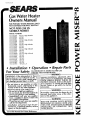 1
1
-
 2
2
-
 3
3
-
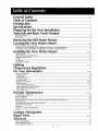 4
4
-
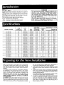 5
5
-
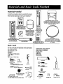 6
6
-
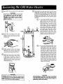 7
7
-
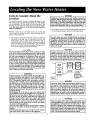 8
8
-
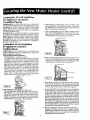 9
9
-
 10
10
-
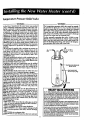 11
11
-
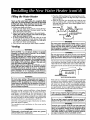 12
12
-
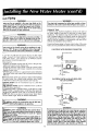 13
13
-
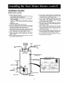 14
14
-
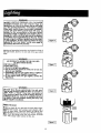 15
15
-
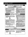 16
16
-
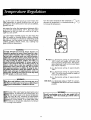 17
17
-
 18
18
-
 19
19
-
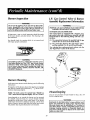 20
20
-
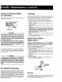 21
21
-
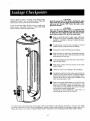 22
22
-
 23
23
-
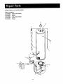 24
24
-
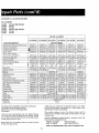 25
25
-
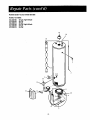 26
26
-
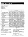 27
27
-
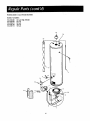 28
28
-
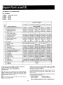 29
29
-
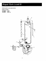 30
30
-
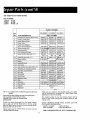 31
31
-
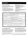 32
32


Kenmore 153335851 User manual
- Category
- Water heaters & boilers
- Type
- User manual
Ask a question and I''ll find the answer in the document
Finding information in a document is now easier with AI
Related papers
-
Kenmore 6-Year Manufacturer's Warranty
-
-
-
-
-
-
-
-
-
Sears 153.33262 User manual
Other documents
-
Apollo Hydroheat A650YRRTL5 User manual
-
Reliance Water Heaters FVIR GAS WATER HEATER User manual
-
HTP Everlast Light Duty Commercial Electric Water Heater Installation Drawings
-
-
State Water Heaters ES6-20-SOMS-K User manual
-
State Water Heaters P6-30-2OT1 User manual
-
-
Maytag Performa HJ675PRDVT User manual
-
-