
Installation
Instructions
Overthe Range
Microwave Oven
Questions?Call800.GE.CARES(800.432.2737)or Visit,,,,_x_ebsite;,t:Hotpointcom I
BEFORE YOU BEGIN
Read these instructions completely and carefully.
• IMPORTANT - S_,,ethese
instructions for local inspector's use.
• IMPORTANT - Obse_,'e_,ll
governing codes and ordinances.
• Note to Installer - Be sure to leave these
instructions with the Consumer.
° Note to Consumer - KeeI)these
instructions for future reterence.
° Skill level - Installation of this appliance requires
basic mechanical and electrical skills.
• Proper installation is the responsibility of the installer.
• Product tailure due to improper installation is not
coxered under the _M_rrantx.
IIIIIIIIIIIIIIIIIIIIIIIIIIIIIIIIIIIIIIIIIIIIIIII
CZ]
I
Fora Spanishversionof thismanual, visitour Websiteat Hotpoint.com.
Para consultaruna versionen espa#olde estemanual de instrucciones,visitenuestrositio
deinternet Hotpointcom.
READ CAREFULLY.
KEEP THESE INSTRUCTIONS.

Installation Instructions
CONTENTS
General information
hnportant Safety Instructions .................................. 3
Electrical Requirements .......................................... 3
Hood Exhaust ....................................... 4, 5
Damage--Shipment/Installation .............................. 6
Parts Included. ......................................... 6
Tools You Will Need ............................................... 7
Mounting Space ...................................................... 7
Step-by-step installation guide
Placement of Mounting Plate ............................ 8-10
Removing tire Mounting Plate ...................... 8
Finding the _4all Studs .................................. 8
Determining _all Plate l.oration .................. 9
Detemiiuiug Rear Mortaring Screw Locations .. 10
Installation Types .................................. 11-22
[]Outside Top ............................
Exhaust
12-14
Attach Mounting Plate to _4"dl ....... 12
Prepm;lfion of Top Cabinet .......... 13
Install the Damper .................. 13
Mount the Microwave Oven ........ 13, 14
Ac!iust the Exhaust Adaptor .......... 14
Connecting Ductwork .......................... 14
_ Outside Back Exhaust 15-18
Preparing Rear _'_fll for
Outside Back Exhaust .......................... 15
Remove Exhaust Adaptor .................... 15
Attach Mounting Plate to 'Wdl ....... 16
Preparation of Top Cabinet .......... 16
Adapting Microwave Blower
tot Outside Back Exhaust ............... 16, 17
Mount the Microwave Oven .......... 18
_] Redrculating ........................................ 19-22
Attach Mounting Plate to _4"fll ....... 19
Preparation of Top Cabinet .......... 19
Adapting Microwave Blower
fl)r Redrrulation ......................... 20, 21
Mount the Microwave Oveu ..........21, 22
Installing the
Charcoal Filter Accessory .................... 22
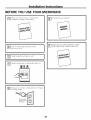
Before You Use Your Microwave .......................... 23
2

Installation Instructions
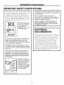
IMPORTANT SAFETY INSTRUCTIONS
This product requires a three-i)rong grounded outlet.
The installer must peril)ira a ground continuity check
on the power outlet box heft)re begilming the
installation to insure that the outlet box is i)roi)erly
grounded, If not i)roi)erly grounded, or if the outlet
box does not ineet electrical requireu_ei_ts noted
(under EI,ECTRICAI, REQUIREMENTS), a qualified
electrician should be elni_loyed to correct any
deficiencies,
CAUTION: For persona]
safety, remove house fuse
or open circuit breaker
before beghmhag
instaJlation to avoid severe
or fatal shock injury,
CAUTION: For persona] safety, the mounting surface
must be capable of supporting the cabinet load, ha
addition to the added weight of this 63-85 pound
product, plus additional oven loads of up to 50 pounds
or a total weight of 113-135 pounds,
CAUTION: For personal safety, this product cmmot
be installed ha cabinet arrmagements such as an island or
a peninsula. It must be mounted to BOTH a top cabinet
AND a wall,
NOTE: For easier hastaJlation mad personal safety, it is
recolmnended that two people install this product.
IMPORTANT - PLEASE RILM) CAREFULLY. FOR
PERSONAL SAFETY, THIS APPLIANCE MUST BE
PROPERLY GROUNDED TO AVOID SEVERE OR
FATAL SHOCK.
The power cord of this
appfimace is equipped with
a three-prong (grounding)
plug which mates with a
staaadaJ_d three-prong
(grounding) wall receptacle
to mh_hnize the possibility
of electric shock hazard
from this appliance.
Ensure proper
ground exists
before use
You should have the wall receptacle mad circuit checked
by a qualified electricima to make sure the receptacle is
properly grounded,
Where a stmadaa'd two-prong wall receptacle is
encountered, it is very hnportant to have it replaced
with a properly grounded three-prong wall receptacle,
installed by a qualified electricima.
DO NOT, UNDER ANY CIRCUMSTANCES, CUT,
DI_ORM OR REMOVE ANY OF THE PRONGS
FROM THE POWER CORD. DO NOT USE WITH
AN ILXTENSION CORD.
ELECTRICAL
REQUIREMENTS
Product rating is 120 volts A(:, 60 Hertz, 15 ami)s and
1.58 kilowatts. This l)roduct inust be connected to a
SUl)ply circuit of the i)roper w)ltage and ti'equency.
Wire size must COlafin'm to the requireu/elatS of the
National Electrical Code or the prewfiling local
code fi_i" this kilowatt rating, The power supply
cord and phlg should be brought to a separate
15- to 20-ami)ere branch circuit single grounded
outlet, The outlet box should be located in the
cabinet above the uficrowave oven. The outlet box
and supply circuit should be installed by a qualified
electrician and confln'n/to the National Electrical
Code or the prewfiling local code.
3

Installation Instructions
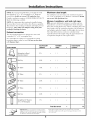
HOOD EXHAUST
NOTE: Read these next two pages only if you plml to vent your exhaust to the
outside. If you plan to recirculate the air back into the room, proceed to page 6.
OUTSIDE TOP EXHAUST (EXAMPLE ONLY)
The following chart describes an example ot one possible
ductwork installation.
DUCT PIECES
EQUIVALENT NUMBER
LENGTH x USED
RoofCap 24 Ft. x
12Ft.StraightDuct 12Ft. x
(6" Round)
Rectangular-to-Round 5Ft. x
TransitionAdaptor*
Equivalentlengthsofductpiecesarebasedon actualtests and
reflectrequirementsfor goodventingperformancewith anyventhood.
(1)
(1)
(1)
Total Length
EQUIVALENT
LENGTH
24 Ft.
12Ft.
5Ft.
41 Ft.
* IMPORTANT: If a rectangula>to-round transition adaptor is used, the bottom cornei_ of the damper
will haxe to be cut to fit, using the tin snips, in order to allow free moxement of the damper.
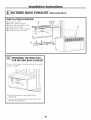
OUTSIDE BACK EXHAUST (EXAMPLE ONLY)
The following chart describes an example ot one possible
ductwork installation.
EQUIVALENT
DUCT PIECES LENGTH* x
Wall Cap 40Ft.
3 Ft.StraightDuct 3Ft. x
3W' x 10"Rectangular)
(_ 90° Elbow 10Ft. x
NUMBER EQUIVALENT
USED = LENGTH
x (1) = 40Ft.
(1) = 3 Ft.
(2) = 20R.
Equivalent lengths of duct pieces are based on actual tests and
reflect requirements for good venting performance with any vent hood.
Total Length = 63 Ft.
NOTE: For back exhaust, care should be taken to align exhaust with space between studs, or wall should be prepared
at the time it is const_ ucted by leaving enough space between the wall studs to accommodate exhaust.
4

Installation Instructions
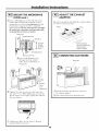
NOTE: If you need to install ducts, note that the total
duct length of 3V{' x 10" rectangular or 6" diameter
round duct should not exceed 140 equivalent feet.
Outside ventilation requires a HOOD EXHAUST DUCT.
Read the following carefiflly.
NOTE: It is important that venting be installed using
the most direct route and with as tew elbows as possible.
This ensures clear venting of exhaust and helps prevent
blockages, Also, make sure dmnpers swing freely and
nothing is blocking the ducts.
Exhaust connection:
The hood exhaust has been designed to mate with
a standard 3V{' x 10" rectangular duct.
If a round duct is required, a rectangula_to-round
transition adaptor m list be used. Do not use less than
a 6" diameter duct.
Maximum duct length:
For s;Kisfhctorv air movement, the total duct length of
3¼" x l 0" rectangular or 6" diameter round duct should
not exceed 140 equivalent feet.
Elbows, transitions, wall and roof caps,
etc., present additional resistance to airflow and are
equi\_dent to a section of straight duct which is longer
than their actual physical size. When calculating the total
duct length, add the equi\:dent lengths of all transitions
and adaptors plus the length of all straight duct sections.
The chart below shows you how to calculate total
equi\_dent ductwork length using the approximate feet
of equivalent length of some typical ducts.
EQUIVALENT NUMBER EQUIVALENT
DUCT PIECES LENGTH x USED = LENGTH
Rectangular-to-Round 5Ft. x ( ) = Ft.
Transition Adaptor*
Wall Cap 40 Ft. x ( ) = Ft.
C)_ 90° Elbow 10 Ft. x ( ) = Ft.
l@ 45° Elbow 5Ft. x ( ) = Ft.
90° Elbow 25 Ft. x ( ) = Ft.
45° Elbow 5Ft. x ( ) = Ft.
Roof Cap 24 Ft. x ( ) = Ft.
Straight Duct 6" Roundor 1 Ft. x ( ) = Ft.
3W' x 10" Rectangular
Total Ductwork = Ft.
* IMPORTANT: If a r( ( tangulal_to-round transilion Equival( nl I( ngths o[ du(t piec( s are |)as( d on aclual lests
adaptor is us(d, th( bottom corners of th( (lamp( 1 and rel]( (t re(ltfir( m( nls for good v( riling performan(( x_ith
_ill have to b( cm to fit, using th( lin snips, in ord(l any vent hood.
to allm_ free lllOVelllelll of Ihe dHlllpel,
5

Installation Instructions
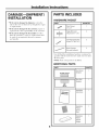
DAMAGE--SHIPMENT/
INSTALLATION
" If the unit is damaged in shipment, return the
unit to the store in which it was bought fin" repair
or rel)laceu/ent,
" If the unit is dainaged by the customer, repair or
replacement is the responsibility of the customer.
• If the unit is damaged by the installer (if other
than the customer), repair or replacement must
be made by arrangement between customer
and installer.
PARTS INCLUDED
HARDWARE PACKET
PART QUANTITY
WoodScrews 1
(¼"x2")
ToggleBolts(and 3
wingnuts)(_6" x3")
Self-AligningMachine 3
j Screws(W'-28x 3Y/')
NylonGrommet 2
(formetalcabinets)
You will find the installation hardware contained in
a packet with the trait. Check to make sHre w)tl have
all these parts.
NOTE: Some extra parts are included.
ADDITIONAL PARTS
PART
TOPCABINETTEMPLATE
REAR
WALL
TEMPLATE
r
INSTRUCTIONS
TopCabinet
Template
RearWall
Template
Installation
Instructions
Separately
Packed
Grease
Filter
Separately
Packed
Exhaust
Adaptor
QUANTITY
1
6

Installation Instructions
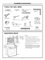
TOOLS YOU WILL NEED
# 1 and#2Phillipsscrewdriver
Tinsnips(forcutting
damper,if required)
Gloves
Safetygoggles
Pencil
Rulerortapemeasureand
t edge
Scissors
(tocuttemplate,if necessary)
Electricdrill with ¾_",W"and%"
drill bits
Saw(saber,holeor keyhole)
......r..,..r.,..r.,..r.,.T.,..r.,..r.,..r.,.r.,.r..,.r.,..r.,..r.,..r.,iTI
(optional)
Fillerblocksor scrap
woodpieces,if needed
fortop cabinetspacing
(usedonrecessedbottom
cabinetinstallationsonly)
Studfinder or Hammer(optional)
__"__-''-_'-'- Ductandmaskingtape
Level
MOUNTING SPACE
66" or More
fromthe Floor
tothe Topof
the Microwave
Backsplash
BottomEdgeof
CabinetNeedsto
be30" or More
from theCooking
Surface
NOTES:
• The space between the cabinets must be
30" wide and fl'ee of obstructions.
• If the space between the cabinets is greater
than 30", a Filler Panel Kit may be used to fill
in the gap between the microwave oven and
the cabinets. Yore" Owner's Manual contains
the kit nmnber tin" wmr model.
• This microwave oven is fl_r installation over
ranges up to 36" wide.
• When installing the microwave oven beneath
smooth, fiat cabinets, be careful to follow the
instructions on the top cabinet template for
power cord clearmlce.
7

Installation Instructions
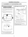
PLACEMENT OF THE MOUNTING PLATE
REMOVING THE MICROWAVE
OVEN FROM THE CARTON/
REMOVING THE MOUNTING PLATE
[]Remove tile installation instructions, filter, glass
tray the exhaust adaptor and the small hardware
bag,. Do not remoxe tile Stxrofoam I)r°tecting, tile
front of tile o_,en.
[]Fold back all 4 carton flaps full) against carton
sides, Then carefifll) roll the oxen and carton oxer
onto the top side, The oxen should be restino, _ in
tile Stx rofoam.
Styrofoam
[]Pull tile carton up and off tile oven.
[] Remove and properly discard plastic bags.
_..._MM Screws
0unting Plate
_ Remove tile 2 screws from tile bottom mounting
plate. Remoxe tile mounting plate and set aside.
This plate will be used with the rear wall template
for mo/mting. REPLACE THE SCREWS,
I-_ FINDING THE WALL STUDS
i
]Find tile studs, using one of tile following
methods:
i i
Wall
Studs
A. Stud finder--a magnetic device that
locates nails.
OR
B. Use a hammer to tap lightly across tile
motmting sm'face to find a solid sotmd.
This will indicate a stud location.
_}_ Afier the find the bvlocating stud(s),
center
probing tile wall with a small nail to find tile edges
of tile stud. Then place a mark half\vav between
the edges. The center of any a(!jacent studs should
be 16" or 24" fl'om this mark.
_Draw a line down the center of the studs,
THE MICROWAVE MUST BE CONNECTED TO
AT LE&ST ONE WALL STUD,
8

Installation Instructions
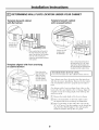
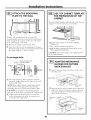
DETERMINING WALL PLATE LOCATION UNDER YOUR CABINET
Template beneath cabinet
with flat bottom
Template beneath cabinet
with recessed bottom
Trimthe rearwall
templatealong
the dotted line.
II
I)raw averticalline onthe wall at
the centerof the 30" to36" wide
space.Tapethe RearWall Template
onto the wall matching the
centerline andtouchingthe bottom
of thecabinet.
Template aligned with front overhang
on cabinet bottom
Drawaline onthe
backwall equaltothe
depthof the front
overhang.Trimthe
rearwall template
alongthe dotted line.
Trimthe rearwall ...........
templatealong
thedotted line.
Drawaverticallineonthewall at
the centerof the 30"or 36" space.
TapetheRearWallTemplateonto
the wall matchingthe centerlineand
touchingthe bottomcabinetframe.
I
THE MICROWAVE MUST BE LEVEL. [
I
Use a lexel to make sure the cabinet bottom is lexel.
Your cabinets may have decorative trim that interieres
with the microwave installation, Remove the decorative
trim to install the microwave i)roperly and to make it
level,
On cabinets with a fl'ont overhang, draw a line on the
back wall at the same depth as the overhang. _Mign the
template to match overhang depth. This will kee I) the
microwave level.
[]Measure the inside depth of the fl'ont overhang.
[]Draw a horizontal line on the back wall to match
the depth of the fl'ont ovefl_ang. See illustration.
[]Draw a vertical line on the wall at the center of the
30" to 36" space. Trim the template on the dotted line.
Tape the Rear X4]_llTemplate to the wall using the
marked centefline and top line as a guide.
9

Installation Instructions
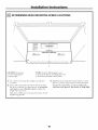
DETERMINING REAR MOUNTING SCREW LOCATIONS
REAR WALl, TEMPLATE
° o o o o o o o o o o o o o o o o o o o o o o o o o o
CAUTION: "_,_ar glo_es
to axoid cutting finge_
on shaq) edges.
NOTE: The Rear Wall Template serves
to position the bottom mounting plate and
to locate the horizontal exhaust outlet.
_lJse a level to check that the template is positioned
acct _I'_telv,
_ I,ocate and mark at least one stud on the lefi or right
side of the centerline. It is important to use at least one
wood screw mounted firmly in a stud to supl)ort the
weight of the microwave.
Mark three additional, evenly spaced locations for the
supplied toggle bolts.
_ Drill in If is a stud,
holes the ulai'ked locations. there
drill a _(; hole fo_ wood screws. For holes that don't
line up with a stud, drill a :'A" hole tot toggle bolts.
NOTE: DO NOT MOUNT THE PLATE AT THIS TIME.
10

Installation Instructions
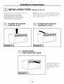
INSTALLATION TYPES
This microwave oven is designed fi>r adaptation to
the following three types of ventilation:
A, Outside Top Exhaust (Vertical Duct)
B, Outside Back I_haust (Horizontal Duct)
C, Recirculating (Non-Vented Ductless)
(Choose A, B or C)
NOTE: This microwave is shiI)ped assembled fl>r Outside
Top Exhaust (except fl)r non-vented models). Select the
type of ventilation required for wmr installation and
proceed to that section,
OUTSIDE TOP EXHAUST
(VERTICAL DUCT)
OUTSIDE BACK EXHAUST
(HORIZONTAL DUCT)
l
_-_ RECIRCULATING
(NON-VENTED DUCTLESS)
A Charcoal Filter Accessory
ICdt is required fi_r the non-
vented exhaust. (See your
Owner's Manual tot the kit
number.)
11

Installation Instructions
OUTSIDE TOP EXHAUST (Vertical Duct)
INSTALLATION OVERVIEW
A1. Attach Mounting Plate to _Mfll
A2. Prepare Top Cabinet
A3. Check Damper Operation
A4. Mount Microwave Oven
A5. Ac!j ust Exha ust Adaptor
A6. (_onnect Ductwork
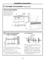
I-_ ATTACH THE MOUNTING
PLATE TO THE WALL
Remove the template fl'om the rear wall. The
mounting plate must be secured to the wall using at
least 3 toggle bolts and one wood screw. The wood
screw inust engage a wall stud.
_ Remove the toggle wings fl'om the bolts.
_ Insert the bolts into the mounting plate
through the holes designated to go into drywall
and reattach the toggle wings to '_A"onto each bolt.
To use toggle bolts:
Mounting
Plate
ml,
Spacingfor Toggles
MoreThanWall
-,,,-I_,-,.-!_,_Thickness
ToggleWings
B01tEnd
_ Place the mounting plate against the wall and
insert the toggle wings into the holes in the wall
to mount the plate.
NOTE: Betore tightening the toggle bolts and the
wood screw(s), check again to be sure that the
mounting plate is level and centered leti to right.
CAUTION: Be careflfl to avoid pinching fingers
between the back of the mounting plate and the wall.
_ Tighten all bolts. Pull the plate away fl'om the
wall to hel I) tighten the bolts. Be careflfl not to
ove>torque the toggle bolts.
12

Installation Instructions
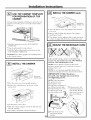
I-_ USE TOP CABINET TEMPLATE
FOR PREPARATION OF TOP
CABINET
The top cabinet template will help you locate the top
SUl)port screw holes, power cord and exhaust outlet
locations.
" Read tile instructions on tile TOP CABINET
TEMPLATE.
" Tape it tmderneath tile top cabinet.
" Drill the holes, fi_llowing the instructions on the
TOP CABINET TEMPLATE.
CAUTION: _4ear satety goggles when drilling holes
in tile cabinet bottom.
I-_ INSTALL THE DAMPER
Remove rear
retaining screw
" Place tile microwaxe in its ui)right position.
" Remo_e tile retainin,* screw at tile rear of tile
i/lotoi" door.
" I,ifl tile blower motor door,
" Slide the exhaust adaptor toward the left side and
into the opening,
" The adaptor should be oriented as shown,
I-_ INSTALL THE DAMPER (cont.)
Dam
Reinstallrear
retainingscrew
" Close tile blower cmer with adaptor and reinstall
Fear scYew,
" Remove tape holding tile damper. Tile damper
should pivot easily.
" Tile adaptor can be a(!justed, lett to right and fl'ont
to back, to align with the house exhaust ductwork,
13
_-'_ MOUNT THE MICROWAVE OVEN
FOR EASIER INSTAI,IATION AND PERSONAl,
SAFETY, X4E RECOMMEND THAT TWO PEOPLE
INSTALL THIS MICROWAVE OVEN.
NOTE: If yore" cabinet is metal, use tile nvhm
grommet aro/md tile power cord hole to prevent
cutting of tile cord.
NOTE: We recommend using filler blocks if the
cabinet front hangs below the cabinet bottom shelf.
IMPORTANT: If filler blocks are
not used, case damage may occur from
overtightening screws.
NOTE: When too/rating
the iilicrowave oven,
thread power cord
through hole in bottom of
top cabinet. Kee I) it tight
throughout Steps 1-3. Do
not pinch cord or lift
oven by pulling
_ I,ift microwaxe, tilt
it forward and hook
slots at back bottom
edge onto fo/ir lower
tabs of mounting
plate.
->.
_ Rotate front of
o_en
up against cabinet
bottoill.

Installation Instructions
MOUNT THE MICROWAVE
OVEN (cont.)
_]nsert a sell:aligning screw through top center
cabinet hole. Temporarily secure tile oven by
turning tile screw at least two full turns after tile
threads have engaged. (It will be completely
tightened later.) Be sure to keep power cord tight.
Be careful not to pinch the cord, especially when
mounting flush to bottom of cabinet.
CabinetFront
Cabinet Bottom Shelf
FillerBlock
__Equivalent
to Depth
of Cabinet
Recess
Self-AligningScrew
MicrowaveOvenTop
[] Insert 2 self:aligning screws
through outer top cabinet
holes, mtlI'II [wo flfll ttlI'nS on
each screw.
Tighten
center
scFew
completely.
[] Tighten tile outer two screws to tile top of tile
microwave oxen. (¥\ hile tightening screws, hold
tile microwaxe oxen in place against tile wall and
the top cabinet.)
/,
_ Install grease filter: See tile Owner's Manual
packed with tile microwave.
4
ADJUST THE EXHAUST
ADAPTOR
Open tile top cabinet and ac!iust tile exhaust adaptor
to connect to tile house duct.
Damper _
ForFr0nt-t0-Backor
Side-to-SideAdjustment,
Slidethe Exhaust
Adaptoras Needed
CONNECTING DUCTWORK
HouseDuct
S
_ Extend tile house duct down to connect to
tile exhaust adaptor.
[] Seal exhaust duct joints using duct tape.

Installation Instructions
OUTSIDE BACK EXHAUST (Horizontal Duct)
INSTALLATION OVERVIEW
B1. Prepare Rear _4_dl
B2. Remove Exhaust Adaptor
B3. Attach Mounting Plate to Wall
B4. Prepare Top Cabinet
BS. Adapt Blower for Back Exhaust
B6. Motmt the Microwave Oven
TEMP LATE . .........
PREPARING THE REAR WALL
FOR OUTSIDE BACK EXHAUST
The rear wall template should be positioned accm'atel}
as shown on page 9.
" Read the instructions on the REAR X4__I,I,
TEMPI ,ATE.
• Cut the oi)enin_, following, the instHictions of the
REAR X,__I,I, TEMPI,ATE.
15

Installation Instructions
I-_ ATTACH THE MOUNTING
PLATE TO THE WALL
Remove the template fl'om the rear wall. The
mounting plate must be secured to tile wall using at
least 3 toggle bolts and one wood screw. Tile wood
screw must engage a wall stud,
[]Remove tile toggle wings fl'om tile bolts.
[]Insert tile bolts into tile mounting plate through
tile holes designated to go into drywall and reattach
tile toggle wings to :_A"onto each bolt.
To use toggle bolts:
Mounting
Plate
,,i,(
Spacingfor TogglesMore
-,,-I-,H,-i-,,_ThanWall Thickness
i
ToggleWings
B01tEnd
_ Place tile motmting plate against tile wall and
insert the toggle wings into the holes in the wall
to I//Otlnt tile plate.
NOTE: Betm'e tightening the toggle bolts and the
wood screw(s), check again to be sure that the
motmting plate is level and centered left to right.
CAUTION: Be careflfl to awfid pinching fingers
between the back of the motmting plate and the wall.
_ Tighten all bolts. Pull the plate away fl'om the
wall to hel I) tighten the bolts. Be carefld not to
ove_=torque the toggle bolts.
USE TOP CABINET TEMPLATE
FOR PREPARATION OF TOP
CABINET
Tile top cabinet template will hel I) you locate tile top
stlI)I)oFt scI'ew holes and poweI" coi'd Ctltotlt.
* Read the instructions on the TOP CABINET
TEMPI,ATE.
" Tape it tmderneath tile top cabinet.
" Drill the holes, fl)llowing the instructions on the
TOP CABINET TEMPLATE.
CAUTION: X_'ear satety goggles when drilling holes
in tile cabinet bottom.
ADAPTING MICROWAVE
BLOWER FOR OUTSIDE
BACK EXHAUST
[] ReIllOXe tile back top center blower illotoi" dooI"
retaining screw.
J
of
BlowerMotor_ _.Microwave
BlowerDoor
Screw
_Open tile blower door it tile backb} lifting /l I)
at
side of the microwaxe. Remo_e and saxe the top
and back retaining screws that hold the blower
iilotoi" ill tile iilici'owa_e.
Retaining
screw
Retaining
screw
16

Installation Instructions
ADAPTING MICROWAVE
BLOWER FOR OUTSIDE
BACK EXHAUST (cont.)
[] Carefllllv slide the blower motor toward the
right,
and lift it partially out of the opening. Note: The
blower wires are long enough to allow flexible
handling while perfimning these steps. Disconnect
the wires only if it is necessary fin" additional
flexH)ilitv.
Backof
Microwave
[] Remoxe the two screws holding the gray-colored
inlet sleexe to the blower trait. Rotate the gray
sleexe as shown until the gra)' arrow lines up with
the "B", back exhaust. Reinstall the two screws.
Remove screws from
Gray Inlet Sleeve _,.
Back of Microwave
_Roll the assembled blower trait so that the
black-colored exhaust outlet faces the back of
the microwave and the gray-colored inlet sleeve
faces downward. NOTE: The gray-colored sleeve
opening must AI._,_VS thce downward to ensure
proper operation of the microwave.
MustFace
Downward
Black
Exhaust
Outlet
Backof
Microwave
] Tilt and the blower trait back into theplace
oi_ening, in the top of the microwave.
CAUTION: Do not pull or stretch the blower
unit wiring. Make sure the wires are not
pinched.
_ Secure the blower unit to the microwaxe with
the two screws remoxed in Step 2.
Retaining
screw
Retaining
screw
[] Close the blower coxer.
[]Attach the exhaust adaptor to the rear of the
microwave b) sliding it into the guides at the
top center of the back of the oxen.
Adaptor
Backof
Microwave
Guide
Guide
BlowerMotor Screw
LockingTabs
Push in securely until it is in the lower locking
tabs. Take care to assure that the damper hinge
is installed so that it is at the top and that the
damper swings fl'eely. Reinstall the original
blower motor screw through the adaptor and
into the back of the microwave.
17

Installation Instructions
MOUNT THE MICROWAVE
OVEN
FOR EASIER INSTAI,IATION AND PERSONAI,
SAFETY, WE RECOMMEND THAT TWO PEOPLE
INSTALL THIS MICROWAVE OVEN.
NOTE: If vour cabinet is metal, use tile nylon
grolmnet around tile power cord hole to prevent
cutting of tile cord.
NOTE: We recommend using filler blocks if tile
cabinet fl'ont hangs below the cabinet bottom shelf.
IMPORTANT: If filler blocks are
not used, ease damage may occur from
overtightening screws.
NOTE: When motmting
tile illicFowa;'e oven,
thread power cord
through hole in bottom of
top cabinet. Keep it tight
throughout Steps 1-3. Do
not pinch cord or lift
oven by pulling cord.
[]I,ifl microwave, tilt
it forward and hook
slots at back bottom
edge onto t()/li" lower
tabs of motmting
plate.
_ Rotate front of
o_en
up against cabinet
bottom.
_lnsert a selt:aligning screw through top center
cabinet hole. Temporarily secure the oven by
turning the screw at least two full turns after the
threads have engaged. (It will be completely
tightened later.) Be sure to keep power cord
fight, Be careful not to pinch the cord, especially
when mounting flush to bottom of cabinet,
CabinetFront
CabinetBottomShelf
FillerBlock
T quivalent
to Depth
ofCabinet
Recess
Self-AligningScrew
MicrowaveOvenTop
[] Insert 2 selt:aligning screws
through outer top cabinet
holes. Ttu'n two flfll ttli'ns
on each screw,
I
_ Tighten center
screw completely.
[] Tighten the outer two screws to the top of the
microwave oven. (While tightening screws, hold
the microwave oven in place against the wall and
tile top cabinet.)
/,
_ Install grease filter. See tile Owner's Manual
packed with the microwaxe.
18

Installation Instructions
RECIRCULATING (Non-VentedDuctless)
INSTALLATION OVERVIEW
C1. Attach Mom_ting Plate to _Mdl
C2. Prepare Top Cabinet
C3. Check Microwave Assemblv
C4. Adapt Blower tin" Recirculation
C5, Mount the Microwave Oven
C6, Install Charcoal Filter
I-_ ATTACH THE MOUNTING
PLATE TO THE WALL
I
Remove the template flxnn the rear wall. The
motmting plate must be secured to the wall using
at least 3 toggle bolts and one wood screw. The
wood screw inust engage a wall stud.
_ Remove the toggle wings fl'om the bolts.
_ Insert the bolts into the motmting plate through
the holes designated to go into drywall and
reattach the toggle wings to sA" onto each bolt.
To use toggle bolts:
Spacingfor Toggles
MoreThanWall
+l._-,,-j_Thickness
ToggleWings
Mounting
Plate
if,
BoltEnd
_ Place the motmting plate against the wall and
insert the toggle wings into the holes in the wall
to mount the plate.
NOTE: Betore tightening the toggle bolts and the
wood screw(s), check again to be sure that the
motmting plate is level and centered left to right.
CAUTION: Be carefld to avoid pinching fingers
between the back of the motmting plate and the wall.
_ Tighten all bolts. Pull the plate away fl'om the
wall to hel I) tighten the bolts. Be carefld not to
ove>torque toggle bolts.
USE TOP CABINET TEMPLATE
FOR PREPARATION OF TOP
CABINET
The top cabinet template will hel I) you locate the top
st/ppoI't screw holes and power cord CtlH)Ilt locations.
" Read the instructions on the TOP CABINET
TEMPI,ATE.
" Tape it tmderneath the top cabinet.
" Drill the holes, following the instructions on the
TOP CABINET TEMPLATE.
CAUTION: _4ear safet} goggles when drilling holes
in the cabinet bottom.

Installation Instructions
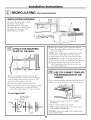
ADAPTING MICROWAVE
BLOWER FOR RECIRCULATION
_ ReIllO_e the back top center blower illOtoi" dooI"
retaining screw.
J
Blower Motor-- Backof
Microwave
BlowerDoor
Screw
[]Open the blower door b) lifting it up at the back
side of the microwaxe. Remo_e and saxe the top
and back retaining screws that hold the blower
illotor in the illiCi'OWa_,e.
Retaining
screw
Retaining
screw
[] Carefiflly slide the blower motor toward the right,
and lift it partially out of the opening. Note: The
blower wires are long enough to allow flexible
hai_dling while perfimnii_g these steps. Disconnect
the wires OlflV if it is necessary fl)i" additional
flexibility.
Backof
Microwave
_ Remoxe the two screws holding the gra) colored
inlet sleeve to the blower unit. Rotate the ora_
sleeve as shown tmtil the gra) arrow lines up with
the "R', Recirculating exhaust. Reinstall the two
scYews.
Remove screws from
Gray Inlet Sleeve
x__"
Back of Microwave
_Roll the assembled blower trait so that the
black-colored exhaust outlet laces the fl'ont of
the microwave and the gra._coh)red inlet sleeve
taces downward.
NOTE: The gra}-c )1 _red sleexe o )ening must
AI.\'_YS tace downward to ensure proper
opei'ation of the i//icrowa_e.
Must Face
Downward
Black
Exhaust
OutletFacing
the Front
Backof
Microwave
2O
Page is loading ...
Page is loading ...
Page is loading ...
Page is loading ...
-
 1
1
-
 2
2
-
 3
3
-
 4
4
-
 5
5
-
 6
6
-
 7
7
-
 8
8
-
 9
9
-
 10
10
-
 11
11
-
 12
12
-
 13
13
-
 14
14
-
 15
15
-
 16
16
-
 17
17
-
 18
18
-
 19
19
-
 20
20
-
 21
21
-
 22
22
-
 23
23
-
 24
24


Ask a question and I''ll find the answer in the document
Finding information in a document is now easier with AI
Related papers
Other documents
-
Frigidaire 40180099010 Installation guide
-
Electrolux E30MH65GSSA Installation guide
-
Frigidaire 40180093700 Installation guide
-
Dometic DOTR16B Over Range Microwave Oven Installation guide
-
-
GE JX52CT Installation guide
-
Samsung SMH7177STE/XAA Installation guide
-
GE JVM2052 User manual
-
GE JVM1665SN2SS Owner's manual
-
Philips BTB2462/05 Quick Setup Guide