Frigidaire FEC30C4ABE Installation guide

Type
Installation guide
_NSTALLAT_ON AND SERVICE MUST BE PERFORMED BY A QUAUF_ED _NSTALLER.
_MPORTANT: SAVE FOR LOCAL ELECTRICAL _NSPECTOR'S USE.
READ AND SAVE THESE _NSTRUCT_ONS FOR FUTURE REFERENCE.
FOR YOUR SAFETY: Do not store or use gasoline or other flammable vapors and liquids in
the vicinity of this or any other appliance.
Cooktop Dimensions
I_- (76i cm)
iMPORTANT INSTALLATION-INFORMATION
All electric cooktops run off a single phase, three-wire
or four-wire cable, 240/208 volt, 60 hertz, AC only
electrical supply with ground
o Please note minimum distances between cooktop and
adjacent and overhead cabinetry is 30" (76,2 cm)
Cooktop Cutout Dimensions
* 30" (762cm) min for unprotected cabinet
24" (61 cm) rain for protected surface
Figure 1
26"CoilElements
30" Ceramk-Glass
30"CoilElements
32" Ceramic-Glass
32"C0ilElements
36" Ceramic-Glass
36"C0ilElements
(36"X18"model)
36"C0ilElements
(36"X211/2"model}
2534(684)
3084(781)
30(762)
32¼ (819)
32I/4(81,9)
3854(933)
36(914)
88(9_4)
219/16(54,8)
21s/s(543}
21_/3(546)
20/4 (514}
204 514)
21s/s(543)
18(457)
2__ 54e
3I/2(89)
8Y4(8,3)
3(76)
854(98)
354(9s)
8_/4(83)
3%(98)
s(76)
2s(635)
28_4(679)
31(78#)
31(787)
34I/4(87)
2553,9
297/s(759)
28A (718)
31X (794)
31I/4(79.4)
36I/8(918)
34sis(873)
204514)
m(48,3)
m(483)
20h (514)
165/s(422}
2022(52.1)
2022(521)
2050,8>
m/4(48,9)
19A (48,9)
20b (52)
1654(42,5)
52_(14)
5(127)
5(12,7)
S84(148)
53A(14.6)
5(12,7)
57/s(14,9)
5(12.7)
All dimensions are in inches (cm)
Only some models are available in Canada.
* Allow 2" (5 cm) space below cooktop to clear the electric cable and allow for installation of the junction box on the wall at the
back of the cooktop
Printed in United States
P/N 318201426 (0508) Rev, A
English - pages 1-6
Espaflol- pages 7-13
Francais - pages 14-20
OverheadCabinetShouldNotExceedaMaximum
Depthof13"(33cm)
orMetal
24"(61cm)Minwhen
BottomofWoodorMetal
Cabinet is Protected by Not
Less Than I/8" Flame
Retardant Millboard Covered
With Not LessThan No, 28
MGS Sheet Steel, 0.015"
(0.4 mm) Stainless Steel,
0,024" (0.6 ram) Aluminum
or 0,020" (0,5 ram) Copper
2 1/2" (6,4 cm) Min,
From Edge of Cutout
to Front Edge of
Countertop
18"
(45.7 cm)
rj Min.
Recommended
Distance Between
Rear Edge of Cutout
10"
( 25.4 cm)
Above Countertop
D
H Min, From Edge of
Cooktop to Nearest
Combustible Wall (Either Side
of Unit),
Approximate Location
of Junction Box
* Letters on this figure refer to chart on front
page except for Go H and J,
To eliminate the
risk of burns or fire by reaching
over heated surfaces, cabinet
storage space located above the
cooktop should be avoided. If
cabinet storage is provided, risk
can be reduced by installing a
range hood that projects
horizontally a minimum of 5"
(12.7 cm) beyond the bottom of
tile cabinets.
12"
(30, 5 cm)
Drawers cannot be used with
this cooktop since burner box
extends G below surface of
countertop,
MODEL ' G ' H ' J
2B" Coil Elements 31/2'' (8,g cm) 3" (7,6 cm) 2" (5,1 cm)
30" Ceramic%lass 4" (102 cm) 7½" (19,1 cm) 2" (5,1 cm)
30" Coil Elements B" (152 cm) 7h" (19,1 cm) 2¼" (5,7 cm)
32" Ceramic-Glass 4" (102 cm) 7h" (19,1 cm) 2" (5,1 cm)
32" Coil Elements B" (15,2 cm) 7½" (19,1 cm) 2¼" (5,7 cm)
3B" Ceramic-Glass 4" (102 cm) 7h" (19,1 cm) 2" (5,1 cm)
3B" Coil Elements B" (152 cm) 3" (7,6 cm) 3" (7,B cm)
(3B" X 18")
36" Coil Elements B" (15,2 cm) 7h" (19,1 cm) 2¼" (5,7 cm)
(36" X 21h")
i
Figure 2 - COUNTERTOP CUTOUT OPENING
Important Notes to the Installer
1. Readallinstructionscontainedintheseinstallation
instructionsbeforeinstallingthecooktop.
2. Removeallpackingmaterialbeforeconnectingthe
electricalsupplytothecooktop.
3. Observeallgoverningcodesandordinances,
4. Besuretoleavetheseinstructionswiththeconsumer.
Important Note to the Consumer
Keeptheseinstructionswithyourowner'sguideforfuture
reference.
IMPORTANT SAFETY
INSTRU S
Be sure your cooktop is installed and grounded
properly by a quaJified installer or service
technician.
These cooktops must be electrically grounded in
accordance with locat codes or, in their absence,
with the Nationa! Electrical Code ANSI/NFPA No.
70--latest edition in the United States, or with
CSA Standard C22.1, Canadian Electrical Code, Part
1, in Canada.
The eJectrical power to the cooktop
must be shut off while line connections are being
made. Failure to do so coutd resutt in serious injury
or death.
Provide Electrical Connection
Install the junction box under the cabinet and run 120/
240 or 120/208 Volt, AC wire from the main circuit
panel. DO NOT connect the wire to the circuit panel at
this time.
Electrical Requirements
Observe all governing codes and local ordinances.
1. A 3-wire or 4-wire single phase 120/240 or 120/208
Volt, 60 Hz AC only electrical supply is required on a
separate circuit fused on both sides of the line (time-
delay fuse or circuit breaker is recommended). DO
NOT fuse neutral. The fuse size must not exceed the
circuit rating of the appliance specified on the
nameplate.
NOTE: Wire sizes and connections must conform with
the fuse size and rating of the appliance in accordance
with the National Electrical Code ANSI/NFPA No. 70-
latest edition, or with CSA Standard C22.1, Canadian
Electrical Code, Part 1, and local (.odes and ordinances.
An extension cord must not be used with this
appliance. Such use may result in a fire, electrical
shock, or other personal injury.
2. The appliance should be connected to the fused
disconnect (or circuit breaker) box through flexible
armored or nonmetallic sheathed (:able. The flexible
armored cable extending from this appliance should
be connected directly to the grounded junction box.
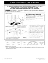
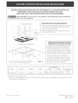
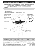
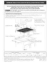
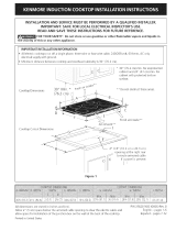
The junction box should be located as shown in
Figure 2 with as much slack as possible remaining in
the cable between the box and the appliance, so it
(.an be moved if servicing is ever necessary.
3. A suitable strain relief must be provided to attach
the flexible armored cable to the junction box.
_Unpacking Instructions
(Models with Ceramic-Glass Smoothtop Only)
Model and Serial Plate
Figure 3 (Under Cooktop)
.
2.
Leave corner supports on cooktop until completion
of Electrical Connection.
Be sure the bottle of cleaner conditioner packed in
the literature bag is left where the user can find it
easily. It is important that the ceramic-glass
smoothtop be pretreated before use.
Electrical Connection
Connect the flexible armored (:able that extends from
the surface unit to the junction box using a suitable
strain relief at the point the armored (:able enters the
junction box. Then make the electrical connection as
follows.
Electrical ground is required on this appliance.
This appliance is equipped with a copper conductor
flexible cable. If connection is made to aluminum house
wiring, use only special connectors which are approved
for joining copper and aluminum wires in accordance
with tile National Electrical Code and local codes and
ordinances.
This appliance is manufactured with a frame connected
green (or bare copper) ground wire.
1. tf connecting to a 3-wire supply cable (U.S.A.
only): If local codes permit connecNon of the
frame grounding conductor to the neutral
(white) wire: (The 3-conductor cord or cable must be
replaced with a 4<onductor cord or cable where
grounding through the neutral conductor is prohibited
in new installations, mobile homes, recreational
vehicles or in other areas where local (.odes do not
permit neutral grounding)
Connect the green (or bare copper) wire (and the
white wire for model with warmer zone) from the
appliance cable to the supply cable ground wire
(white or bare)inside the junction box. Connect the
remaining wires inside the junction box (see Figure 4
or 5) from the power supply cable to tile matching
colors of tile appliance cable wires.
Cable from Power Supply
Ground Wire
Red
Wires
Black
Wires
Box
GroundWire
(Bareor GreenWire) Conduit
Connector(or CBAlisted)
Cablefrom appliance
Figure 4- U.S.A. Only
3-WIRE GROUNDED JUNCTION BOX
Cable from Power Supply
Ground Wire
Red
Box
Wire
Ground Wire U.L-Listed Conduit
(Bare or GreenWire) Connector (or CSA listed)
Cable from appliance
Figure 5 - U.S.A. Only
Models 36" with Warmer Zone Only
3-WtRE GROUNDED JUNCTION BOX
_tmproper connection of aluminum
house wiring to copper leads can result in a short
circuit or fire. Use only connectors designed for
joining copper to aluminum, and follow the
manufacturer's recommended procedure closely.
.
tf connecting to a 4-wire supply cable (also
mobile homes): The appliance frame must not be
connected to the neutral wire of the 4-wire electrical
system. Connect the appliance white wire (if a 4-wire
appliance cable is supplied) to the power supply cable
white wire. Cap tile white wire from the power
supply cable if a 3-wire appliance cable is supplied.
Connect the remaining wires from the supply cable to
tile matching color wires from the appliance cable
(see Figure 6 or 7). The green (or bare copper) wire
must now be used to ground the appliance in
accordance with local electrical codes. The green (or
bare copper) wire from the power supply cable is
grounded inside tile house service panel.
Cable from Power Supply
Ground Wire / _U.L-Listed Conduit
(Bare or GreenWire) Connector (or CSA listed)
Cable from appliance
Figure 6 - 4-WIRE GROUNDED JUNCTION BOX
Cable from Power Supply
Ground Wire _--c--_
(BareorGreenWire)__
Junction Box _ _ U,L,-Listed Conduit
Connector (or CSA listed)
Cable from appliance
Figure 7 - 4-WIRE GROUNDED JUNCTION BOX
Models 36" with Warmer Zone Only
DO NOT ground to a gas supply pipe.
DO NOT connect to electrical power supply until
appliance is permanently grounded. Connect the
ground wire before turning on the power.
Cooktop Installation
1. All Ceramk-Glass Cooktops
Visually inspect the cooktop for damage. Also make
sure all cooktop screws are tight (see Figure 8).
SCREWS
Figure 8
Set the cooktop into the countertop cutout,
NOTE: Do not use caulking compound; cooktop
should be removable for service when needed.
Do not remove the nylon spacers on
the edges of the cooktopo These spacers center the
cooktop in the space provided. The cooktop must
be centered to prevent excess heat buildup that
may resuJt in heat damage or fire (see Figure 9).
6 NYLON SPACERS
POSITION BRACKETS
/
ON UNIT CUTOUT .<--" _-_ B>_
CENTERLINE .<_s:;>" ._ ......
2 RETAINER "_'_ .............
BRACKETS ........
Figure 9
The retainer brackets MUST be installed, to meet
local codes or, in their absence, with the National
EJectricaJ Code ANSJ/NFPA No. 70--latest edition,
or with CSA Standard C22.1, Canadian EJectricat
Code, Part 1 (see Figure 10).
NYLON
SPACER
COUNTERTOP
Retainer Brackets Must
fBe At Lest 1/16"
Installed
(016 crn) BELOW
Countertop
RETAINER
BRACKET
Figure 10
Models: 26" and 36" (36" X 18") Coil Elements
Cooktops
Set the cooktop into the countertop cutout. Lift tile
cooktop and fasten the ends of tile box to the counter
with wood screws (figure 11). Lower the cooktop.
Align tile knobs on the shafts and press down with
even pressure.
COOKTOP _. COUNTERTOP
J _'SCREW
BURNERBOX
Figure 11
Models: 32" Coil Elements Cooktops
1. Place cooktop into countertop opening and
center unit in cutout.
2. Remove all surface units and drip bowls.
3. Unit (:lamp down information. Once unit is
installed in counter opening, you must clamp unit
down as shown in figure 12.
4. Put back all surface units and drip bowls.
5. Make electrical connections as outlined in
"Electrical Connection" section.
Read/ down through surface unit openings and install the four
hold down retainers with screws as shown Be certain cooking
top is firmly retained to counter top.
4_
_BURNER BOX
Figure 12
ModeJs: 30" and 36" (36" X 21Y2") Coil EJements
Cooktops
These cooktops are designed to fit various cutout
sizes. The minimum and maximum cutout openings
are shown in figure 1.
If cooktop isto be used in new installation, use
minimum cutout dimensions in figure I.
Attach cooktop to cabinet using wood screws
through holes in vertical walls of burner box.
[f cooktop is to be installed as a repJacement
in an existing countertop opening (not
exceeding maximum cutout dimensions as
shown in figure 1), the following steps must
be taken:
1. Insert 4 screws and installation spacers through
holes in vertical walls of burner box (see figure
13).
2. Place cooktop into countertop opening and
(.enter unit in cutout,
SPACER
SCREW
Figure 13
3. Tighten each screw finger tight or until spacers
are snug against burner box walls.
4. Prior to tightening installation screws, exert
downward pressure on burner box to assure
flanges on burner box rest firmly on counter.
Tighten all screws evenly.
5. Unit clamp down information. Once unit is
installed in counter opening, you must clamp unit
down as shown in figure 14.
6. Make electrical connections as outlined in
"Electrical Connection" Section.
To clamp down, insert bracket with offset side of angle into slot
on each side of unit. The screw should then be run through
bracket and against bottom of counter. Tighten until draws
down.
BURNERBOX_
Figure 14
Checking Operation
Refer to the Owner's Guide for operation.
Do not touch cooktop glass or elements.
They may be hot enough to burn.
Model and Serial Number Location
The serial plate is located under the cooktop or in tile
burner box and can be seen by lifting up tile main top of
unit.
When ordering parts for or making inquires about your
cooktop, always be sure to include the model and serial
numbers and a lot number or letter from the serial plate
on your cooktop.
Before You Call for Service
Read tile Avoid Service Checklist and operating
instructions in your Owner's Guide. It may save you time
and expense. The list includes common occurrences that
are not the result of defective workmanship or materials
in this appliance.
Refer to the warranty in your Owner's Guide for our
service phone number and address. Pleasecall or write if
you have inquiries about your product and/or need to
order parts.
  • Page 1 1
  • Page 2 2
  • Page 3 3
  • Page 4 4
  • Page 5 5
  • Page 6 6
  • Page 7 7
  • Page 8 8
  • Page 9 9
  • Page 10 10
  • Page 11 11
  • Page 12 12
  • Page 13 13
  • Page 14 14
  • Page 15 15
  • Page 16 16
  • Page 17 17
  • Page 18 18
  • Page 19 19
  • Page 20 20

Frigidaire FEC30C4ABE Installation guide

Type
Installation guide

Ask a question and I''ll find the answer in the document

Finding information in a document is now easier with AI