Page is loading ...

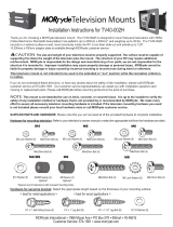
SM-VM-ART1-IW-L
Strong™ Razor Series Articulating VersaMount
INSTRUCTION MANUAL

Pg. 2
CAUTION:
This wall mount is intended for use only with the maximum weight
of 75 lbs./34 kg. Use with heavier than the maximum weight
indicated may result in instability causing possible injury.
1. Warnings
• Installationofthisproductshouldbedonebyaqualiedprofessional.
• Do not begin installation before reviewing and understanding these instructions.
• Ensure the mounting wall used can safely support 4 times the combined weight of the mount and chosen display.
• Under no circumstances should this product be mounted to metal studs.
• The manufacturer does not accept responsibility for incorrect installation.
2. Tools Required
• Power Drill
• 1/4” Drill Bit
• Phillips Head Screw Driver
• Level
• 1/2” (13mm) Socket Wrench
• Stud Finder (optional, recommended for wood stud mounting)
• Zip Ties (for wire management)

Pg. 3www.snapav.com Support: (866) 838-5052
3. Hardware
Bag 1
Bag 2
Bag 3
Bag 4
(T1) Small 4mm
Allen Key
(1)
(T2) Large
4mm
Allen Key
(1)
(T3)
8mm Socket
Wrench (1)
(A) Phillips Head
Machine Screw,
M4x10 (4)
(B) Phillips Head
Machine Screw,
M4x20 (4)
(C) Phillips Head
Machine Screw,
M4x30 (4)
(D) Phillips Head
Machine Screw,
M5x10 (4)
(E) Phillips Head
Machine Screw,
M5x20 (4)
(F) Phillips Head
Machine Screw,
M5x30 (4)
(I) Phillips Head
Machine Screw,
M6x10 (4)
(J) Phillips Head
Machine Screw,
M6x10 (8)
(K) Phillips Head
Machine Screw,
M6x20 (4)
(L) Phillips Head
Machine Screw,
M6x30 (4)
(M) Phillips Head
Machine Screw,
M8x10 (4)
(N) Phillips Head
Machine Screw,
M8x20 (4)
(O) Phillips Head
Machine Screw,
M8x30 (4)
(P) Phillips Head
Machine Screw,
M8x40 (4)
(V) Washer, M5,
6.5x18x2
(2)
(U) Drywall Anchor
10x80 (4)
(W)
M5 Lock nut (2)
(G) Small Nylon Spacer,
OD12xID5.5x5 (8)
(H) M5 Washer,
M5x12x1 (16)
(R) M8 washer,
M8x19x2 (8)
(X) M5 Nylon Washer
5.5x18x2
(2)
(T) Washer
9.5x21x2 (4)
(S) M8x90 Lag Bolt (4)
(Q) Large Nylon Spacer,
OD15xID8.5x5 (8)

Pg. 4
4. Overview
Thank you for purchasing a great product from Strong™. We appreciate your purchase and are committed to providing the highest
quality products possible. The Strong VersaMount™ is designed to provide the best in-wall TV-mounting solution for installers adding
equipmentbehindlow-proledisplaysandotherwall-mountedequipment.Itcaneasilybeinstalledinnewjobswiththeincludeddust
cover to protect the VersaMount™ during construction.
Inside the enclosure, components may be mounted using the built-in attachment points with expansion pins or zip ties. Add a wattbox
(not included) to the bottom of the VersaMount™ for the best power and space-saving solution.
Using Knockouts
The knockouts on the top and bottom of the VersaMount may be used
for installing low voltage rings or for outlet boxes. If an outlet box is
installed, it must be a metal junction box with integrated work supports to
allow for secure mounting.
Note:To ensure re safety, the silicone grommets must remain in the
VersaMount. When using these as wire guides, slit each grommet down
the middle in a “+” shape, never remove them.
Modules
The back wall of the VersaMount has holes and knockouts stamped into
it on 6” centers to allow for easy structured can module installation. Use
a ¼” drill bit to open more of the knockout stamps as needed to mount
equipment.
5. Installing Equipment into the Strong VersaMount™
TheVersaMountallowsforavarietyofequipmentcongurationoptions.Experimentwiththeequipmentcongurationtodetermine
thebestinstallationmethod.ForimagesofdifferentcongurationsofequipmentinstalledintheVersaMount,seetheVersaMount
product page and Support Tab at www.SnapAV.com.
6. New Work Installation Instructions
The SM-VM-ART1-IW-L dust cover is designed to protect the inside of the Strong VersaMount in new work applications before drywall
is hung on the studs.
Note: Determine what thickness the drywall will be before installing the enclosure.
Strong VersaBox™ Installation (after drywall is installed)
1. Open any knockouts in the VersaBox that will be used for wiring or electrical.
2. Pull the wires out of the wall opening and pull them into the desired openings
of the VersaBox.
3. Insert the box into the opening left where the bracket is. Use standard lag
bolts to secure the box to the studs on each side of the enclosure.
4. UsethedustcovertoprotecttheinsideoftheVersaMountduringnishing
work.
Go to the SM-VM-ART1-IW-L product page at www.SnapAV.com for tips and
ideas on how to install equipment into the VersaMount.
Lag bolts will need to
reach to studs on
either side of the box.
Secure 2 screws in
each side through
the allotted holes.

Pg. 5www.snapav.com Support: (866) 838-5052
7. Old Work Installation Instructions
8. Optional Compact Wattbox
1. Mark the desired height of the top of the SM-VM-ART1-IW-L on the
wallbetweentwostudcenters.Useastud nder to locate thestud
locations.
2. Use the cut-out template to mark the wall, using a level to line it up
correctly.
3. Carefully cut the opening using a drywall saw.
4. After the hole is cut, test t the box, and clean up the opening as
needed.
5. Insert the box into the opening. Using a #1 Phillips screwdriver, secure
the box to the studs with 2 lag bolts located on both sides of the box.
Lag bolts will need to
reach to studs on
either side of the box.
Secure 2 screws in
each side through
the allotted holes.
Note: If you are installing the optional WB-200VB, insert it prior to mounting
the TV. If drywall is installed, see section 8.1.
Remove the bottom panel by unscrewing the 4 pre-installed screws. Insert
the compact wattbox, and re-thread the four screws to permanently secure
it. For further installation information, see the WB-200VB manual.
Note: The single-gang knockout located at the bottom right corner of the box
may also be utilized for a single-gang 2-outlet box.
8.1 Removing the Arm-Stop
If drywall is already installed, the arm-stop may have to be temporarily
removed to allow for installation clearance of the WB-200VB. Remove the
two screws attaching the arm-stop to the rear of the enclosure to remove
the arm-stop. Replace the arm-stop after the wattbox has been secured
within the enclosure to keep the mount from damaging installed equipment.

Pg. 6
9. Install the Display Adapter Plate
10. Determine the Correct Mounting Height
A. Carefully lay the display face-down on a soft surface.
B. Locate the four mounting holes in the back of the
display housing. Try to thread screws (A through L) in
until the correct thread is found for the holes.
C. Lay the adapter plate over the holes in the display
(directional arrow facing up), and check the clearance
between the TV and the plate. Make sure the mounting
holes match up properly to four of the holes in the
adapter plate. The adapter plate should be centered
on the back of the display. See the available VESA
patterns in Figure 1.
D. If the plate won’t sit at against the back of the
television, spacers (G and Q) and washers (H and R)
may be placed between the display and the plate as
needed.
E. Fasten the plate to the display using a #2 Phillips
screwdriver. Use screws long enough to thread
securely into the display without bottoming out.
A. Decide the height where the top edge of the display should
be once installed. (Height)
B. Measure and record the distance between the top of the
display and the top of the display adapter plate (Figure 3).
Makesuretomeasurefromtheatareaontopoftheplate,
not the curved area. (Dimension A)
C. Insert the Height and Dimension A into the formula:
D. Mark the location of the top edge of the enclosure and use the mouting template to determine the cut out of wall.
(Height) – (A) + 5/8” = Top Edge of Enclosure
Note: The adapter plate (Figure 1) is designed for use with these
VESA patterns: 100x100, 100x200, 200x100, and 200x200. For
a 400x400 VESA pattern, attach the extension adapter (Figure 2)
with the 4 included bolts (J).
Warning: Over-tightening can damage the bolts or the display
and is not covered under warranty. Make sure the fasteners are
tight enough not to rattle loose while the mount is in use.
Figure 1.
Figure 2.
Figure 3.
200
100
100
200
A
Measure from
flat edge of plate
to top of TV

Pg. 7www.snapav.com Support: (866) 838-5052
11. Detaching the Arm Assembly from the Enclosure
12. Attaching the Display to the Arm Assembly
A. Loosen the two upper clamping screws on the arm assemble, and loosen the 2 lower screws.
B. Remove the upper, middle screw from the lower left corner of the rear of the VersaBox panel.
Note: Do not reinstall this screw if you wish to remove the arm after the VersaMount has been installed in the
wall, as you will no longer have access to this screw.
C. Pull the mount arm up and away from the can to detach the mount.
1. Lift the display and place it on the end of the arm assembly as shown in
Figure 10.
2. Secure the display using the two Nylon washers (X), two metal washers
(V), and lock nuts (W). Be sure to place the Nylon washer between the
mount and the metal washer. This will allow for easier tilt adjustments
later.
3. Tighten the nuts with the 8mm socket wrench (T3).
(X) (V) (W)
Figure 10.
Note: It is not recommended to remove the Arm Assembly from the enclosure, but you may if so desired by carefully following
the instructions below.
Screws
Untighten
Untighten
Screws

Pg. 8
13. Adjusting Display Position
13.1 Horizontal Level Adjustments
13.2 Vertical Position Adjustments
1. Loosen the two locking nuts (W) at the bottom of the arm assembly end plate using the 8mm socket wrench (T3). (Figure 11)
2. Place a level on top of the display, and rotate the display until it is horizontally level. (Figure 12)
3. Tighten the locking nuts at the bottom of the arm assembly end plate and then loosen them ¼ turn. This will allow for the
display to be positioned with minimal effort.
4. After adjustment is complete, tighten the nuts.
The vertical position of the display can be adjusted +/- 3/8” from the pre-adjusted centered position. This is achieved
by tightening (up) or loosening (down) the vertical adjustment screw located on the arm plate.
1. 1. Extend the arm to access the vertical position adjustment.
2. 2. Loosen the four lock-nuts on the rear of the arm plate using the 8mm socket wrench (T3). (Figure 13)
3. 3. Using the Large 4mm Allen wrench (T2), tighten the adjustment screw to raise the display, or loosen the screw to lower
the display. (Figure 14)
4. 4. Tighten the four lock nuts on the rear of the arm plate using the 8mm socket wrench (T3).
Figure 11. Figure 12.
Horizontal Level
Adjustment Nuts (W)
+/- 4°
Figure 13. Figure 14.
Lock Nuts
Large 4mm Allen Key (T2)

Pg. 9www.snapav.com Support: (866) 838-5052
13.3 Adjusting Home Position (Fully Retracted)
13.4 Tilt Adjustments
The mount includes a home position latch that secures the arm
to the wall mount. This prevents the display from being pushed
away from the wall due to cabling.
Note: Only the TV Plate side of the latch is pre-installed. The
home position latch clip requires installation and adjustment.
Tilt adjustments usually do not require loosening any
bolts or screws. The tilt plate fasteners have been pre-
adjusted for easy adjustment with most TVs. However,
heavier TVs may sag due to the extra weight.
If this occurs, evenly tighten the lock nuts on each side
of the end plate using the small 4mm Allen Wrench (T1)
until the display no longer sags. (Figure 16)
Figure 15.
Figure 16.
11°
5°
Tilt Adjustment Nuts
(2 per side)
1. Extend the arm out away from the wall.
2. Attach the home position latch to the wall arm assembly using the
three screws as shown in Figure 15. Use a #2 Phillips screwdriver
to adjust the screws.
3. Leave the screws loose enough to be able to adjust the latch and
set it at the top of its travel.
4. Push the display back to the wall.
5. If no “click” isheard as the armispushed at, adjustthelatch
downward and test again.
6. Repeat these steps until a “click” is heard and the display latches completely to the wall mount.
7. After the latch is set correctly, tighten the screws completely.

Pg. 10
14. Notes

Pg. 11www.snapav.com Support: (866) 838-5052

Pg. 12
15. Dimensions
Warranty
Limited Lifetime Warranty
All Strong back-boxes and brackets have a Lifetime Limited Warranty. This warranty includes parts and labor repairs on all
components found to be defective in material or workmanship under normal conditions of use. This warranty shall not apply to
products that have been abused, modied, or disassembled. Products to be repaired under this warranty must be returned to
SnapAV or a designated service center with prior notication and an assigned return authorization number (RA).
Lifetime
Contacting Technical Support
Phone: (866) 838-5052 Email: Techsupport@snapav.com
© 2014 Strong™
150113-0900
14.93”
14.53”
18.56”
18.97”
13.98”
15.17”
15.04”
14.03”
15.75”
[400]
7.87”
[200]
15.75”
[400]
7.87”
[200]
3.75”
3.75”
.915”
(Optional Wattbox Addition)
≈ 5.7”
/