Emerson PB Series Owner's manual
- Category
- Oxygen Equipment
- Type
- Owner's manual
This manual is also suitable for

Model 1181 PB
Dissolved Oxygen Two-Wire Transmitter
Instruction Manual
PN 51-1181PB/rev.A
April 2003

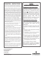
DANGER
HAZARDOUS AREA INST
ALLATION
INTRINSICALL
Y SAFE INSTALLATION
Installations in hazardous area locations must
be carefully evaluated by qualified on site
safety personnel. Transmitter and Sensor
alone are not
Intrinsically safe. To secure and
maintain an intrinsically safe installation, a
certified safety barrier must be used and the
installation must comply with the governing
approval agency (FM, CSA or
BASEEFA/CENELEC) installation drawing
requirements (see Section 2.0 - Installation).
EXPLOSION-PROOF INST
ALLATION
Caution: Sensors are not explosion-proof. If the
sensor must be installed in a hazardous location
an intrinsically safe system must be
implemented.
To maintain the explosion-proof rating of the
transmitter, the following conditions must be
met:
• Discontinue power supply before removing
enclosure covers.
• Transmitter covers must be properly
installed during power on operation.
• Explosion proof "Y" fittings must be
properly installed with sealing compound
prior to applying power to the transmitter.
• Serial tag cover over the external Zero and
Span adjustments must be in place.
• See Installation Section for details.
Proper installation, operation and servicing of
this instrument in a Hazardous Area Installation
is entirely the responsibility of the user.
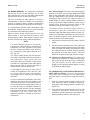
ESSENTIAL INSTRUCTIONS
READ THIS PAGE BEFORE PROCEEDING!
Rosemount Analytical designs, manufactures, and tests
its products to meet many national and international
standards. Because these instruments are sophisticated
technical products, you must properly install, use, and
maintain them to ensure they continue to operate within
their normal specifications. The following instructions must
be adhered to and integrated into your safety program
when installing, using, and maintaining Rosemount
Analytical products. Failure to follow the proper
instructions may cause any one of the following situations
to occur: Loss of life; personal injury; property damage;
damage to this instrument; and warranty invalidation.
• Read all instructions prior to installing, operating, and
servicing the product. If this Instruction Manual is not
the correct manual, telephone 1-800-654-7768 and the
requested manual will be provided. Save this Instruction
Manual for future reference.
• If you do not understand any of the instructions, contact
your Rosemount representative for clarification.
• Follow all warnings, cautions, and instructions marked
on and supplied with the product.
• Inform and educate your personnel in the proper
installation, operation, and maintenance of the product.
• Install your equipment as specified in the Installation
Instructions of the appropriate Instruction Manual and
per applicable local and national codes. Connect all
products to the proper electrical and pressure sources.
• To ensure proper performance, use qualified personnel
to install, operate, update, program, and maintain the
product.
• When replacement parts are required, ensure that
qualified people use replacement parts specified by
Rosemount. Unauthorized parts and procedures can
affect the product’s performance and place the safe
operation of your process at risk. Look alike
substitutions may result in fire, electrical hazards, or
improper operation.
• Ensure that all equipment doors are closed and
protective covers are in place, except when
maintenance is being performed by qualified persons,
to prevent electrical shock and personal injury.
Emerson Process Management
Rosemount Analytical Inc.
2400 Barranca Parkway
Irvine, CA 92606 USA
Tel: (949) 757-8500
Fax: (949) 474-7250
http://www.RAuniloc.com
© Rosemount Analytical Inc. 2001

i
Model 1181 PB TABLE OF CONTENTS
MODEL 1181 PB
TWO-WIRE TRANSMITTER
TABLE OF CONTENTS
Section Title Page
1.0 DESCRIPTION AND SPECIFICATIONS ............................................. 1
1.1 Features and Applications .................................................................... 1
1.2 Physical Specifications – General ........................................................ 2
1.3 Performance Specifications – General ................................................. 2
1.4 Performance Specifications at 25°C..................................................... 3
1.5 Ordering Information............................................................................. 3
2.0 INSTALLATION .................................................................................... 4
2.1 Unpacking and Inspection .................................................................... 4
2.2 Mechanical Installation ......................................................................... 4
2.3 Hazardous Locations-Explosion-Proof Installation ............................... 4
2.4 Wiring – General................................................................................... 5
2.5 Hazardous Locations-Intrinsically Safe Installation .............................. 5
2.6 Dissolved Oxygen Sensor .................................................................... 6
3.0 DESCRIPTION OF CONTROLS .......................................................... 16
3.1 Description of Controls ......................................................................... 16
4.0 CONFIGURATION ............................................................................... 20
4.1 General................................................................................................. 20
4.2 Range Selection ................................................................................... 20
4.3 Course Span Adjustment...................................................................... 20
4.4 External Zero and Span Adjustment..................................................... 20
4.5 Digital Display....................................................................................... 20
5.0 START UP AND CALIBRATION .......................................................... 21
5.1 General................................................................................................. 21
5.2 Transmitter Zero ................................................................................... 21
5.3 Air Calibration ....................................................................................... 21
5.4 Calibration for Measuring ppb Oxygen ................................................. 22
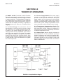
6.0 THEORY OF OPERATION .................................................................. 23
6.1 Model 1181 PB ..................................................................................... 23
6.2 Dissolved Oxygen Measurement Sensor ............................................. 24
7.0 DISASSEMBLY/REASSEMBLY PROCEDURE................................... 26
7.1 Disassembly Procedure........................................................................ 26
7.2 Reassembly Procedure ........................................................................ 26
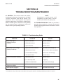
8.0 TROUBLESHOOTING/MAINTENANCE .............................................. 27
8.1 General................................................................................................. 27
8.2 Troubleshooting.................................................................................... 27
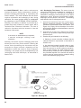
8.3 Maintenance ......................................................................................... 28
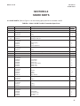
9.0 SPARE PARTS .................................................................................... 31
9.1 Spare Parts........................................................................................... 31
10.0 RETURN OF MATERIAL...................................................................... 33
10.1 General................................................................................................. 33
10.2 Warranty Repair ................................................................................... 33
10.3 Non Warranty Repair............................................................................ 33

ii
Model 1181 PB TABLE OF CONTENTS
TABLE OF CONTENTS (CONT'D)
LIST OF FIGURES
Section Title Page
2-1 Mounting and Dimensional Drawing..................................................... 7
2-2 Schematic System, FM Explosion Proof Approved .............................. 8
2-3 Transmitter Wiring ................................................................................ 9
2-4 Schematic System, FM I.S. Approved - Entity (1 of 3) ......................... 10
2-4 Schematic System, FM I.S. Approved - Entity (2 of 3) ......................... 11
2-4 Schematic System, FM I.S. Approved - Entity (3 of 3) ......................... 12
2-5 Schematic System, CSA I.S. Approved - Loop .................................... 13
2-6 Flow Chamber with Sensor Dimensions............................................... 14
2-7 Typical Installation with Siphon Breaker............................................... 15
3-1 Range Selector Switch and Course Span Adjust ................................. 16
3-2 Display PCB ......................................................................................... 17
3-3 External Zero and Span Adjust............................................................. 18
3-4 Digital Display....................................................................................... 19
5-1 Matrix Cover, Range Selection............................................................. 22
6-1 Simplified Block Diagram...................................................................... 23
8-1 Recharge Kit......................................................................................... 28
8-2 Exploded View of Sensor/Membrane Assembly................................... 29
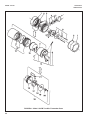
9-1 Model 1181 PB Two-Wire Transmitter Parts ........................................ 32
LIST OF TABLES
Section Title Page
8-1 Troubleshooting Guide ......................................................................... 27
9-1 Model 1181 PB Two-Wire Transmitter Spare Parts ............................. 31

1
MODEL 1181 PB SECTION 1.0
GENERAL DESCRIPTION AND SPECIFICATIONS
SECTION 1.0
DESCRIPTION AND SPECIFICATIONS
• TWO-WIRE FIELD MOUNTED TRANSMITTERS. Ideal for multiple loop installations where
central data processing and control are required. Field mounting near the sensor for ease in
routine calibration.
• NEMA 4X WEATHERPROOF, CORROSION-RESISTANT, DUAL COMPARTMENT HOUSING
provides maximum circuit protection for increased reliability in industrial environments.
• HAZARDOUS AREA INSTALLATION. Certified NEMA 7B explosion-proof and intrinsically safe
when used with an approved sensor and safety barrier.
• COMMONALITY OF PARTS reduces inventory required to support different field
measurements.
• SWITCH SELECTABLE RANGES further reduces inventory by permitting calibration of one
Model to virtually any Tag Number requiring the same measurement.
• EXTERNAL ZERO AND SPAN, 20-turn potentiometers provide for fine calibration of the
isolated 4-20 mA output signal.
1.1 FEATURES AND APPLICATIONS
The Rosemount Analytical Two-Wire PB Dissolved
Oxygen Transmitter, with the Model 120012 Dissolved
Oxygen Sensor Assembly, is used to accurately and
continuously measure dissolved oxygen at parts per
billion levels in applications such as boiler feed water,
food and beverage applications, deaerated sea water
for desalinization and deoxygenated brine for oil well
injection.
The Model 1181PB includes all the circuitry necessary
for the measurement and transmission of an isolated 4-
20 mA signal. This current output signal is compatible
with, and provides a reliable front end measurement for,
virtually any process monitoring and control scheme.
The transmitter is housed in a NEMA 4 weatherproof,
NEMA 7 explosion-proof enclosure and is designed for
intrinsically safe operation. Features include external
20-turn ZERO and SPAN controls, and a dual
compartment housing with a moisture barrier that totally
isolates the electronic circuitry from the field wiring and
calibration terminals.
The electronic circuitry is mounted on printed circuit
boards (PCB’s) which plug directly into the moisture
barrier. The printed circuit boards are removed as a unit
and may be replaced individually or as a unit to expedite
maintenance.
The Model 1181PB is available with an analog meter, a
3¼ digit LCD display, or as a blind version if local
indication is not required. The measurement range is
field selectable and does not require removal of the
electronic circuitry. The range switch provides a full
scale span of 0-50, 0-100 or 0-200 PB, plus an air
calibrate position. A matrix is provided for convenient
indication of the proper switch position for a desired
measurement range.
The 3¼ digit LCD display can be calibrated for the
desired range using the “Display” zero and span pots
found on the LCD display board (these are not the same
as the “external” ZERO and SPAN controls), and the
decimal positioning switch, also located on the display
PCB. The display is directly proportional to the 4-20 mA
isolated current output. To facilitate installation, an
optional two-inch pipe/wall mounting bracket (Code 07)
is available.
The Model 120012 is a patented polarographic
dissolved oxygen sensor designed for long-life, high
accuracy and rugged use in industrial environments.
Constructed of Polypropylene and Teflon, the sensor
provides three to six months of continuous operation
before recharging, which simply involves adding a new
supply of liquid electrolyte and a new Teflon membrane.
To further reduce maintenance costs and down time, the
Teflon membrane is recessed for protection. Should it
become damaged, non-technical personnel can easily
replace it in a matter of minutes without concern for
variable tension, membrane stretching or folding.
The Model 120012 sensor comes with a Flow Chamber
Assembly, available only in PVC, that allows the sensor
to be mounted “inline”. The nozzle directs the sample
flow onto the cathode of the sensor. The direct
impingement of sample reduces sample flow
requirements. It also improves the response to changes
in dissolved oxygen while providing a cleaning action to
the sensor membrane.

2
MODEL 1181 PB SECTION 1.0
DESCRIPTION AN SPECIFICATIONS
1.2 PHYSICAL SPECIFICATIONS –
GENERAL
Enclosure: NEMA 4X, weatherproof and corrosion-
resistant, NEMA 7B, explosion proof
Hazardous Area Classification - Explosion Proof:
FM: Class I, Groups B, C, & D, Div. 1
Class II, Groups E, F, & G, Div. 1
Class III
CSA: Class I, Groups C, & D
Class II, Groups E, F, & G
Class III, Encl 4
Class I, Groups A, B, C & D. Div. 2
Encl 4, Factory Sealed
Hazardous Area Classification - Intrinsic Safety:
FM: Class I, II & III, Div. 1
CSA: Class I, Groups A, B, C, & D
Encl 4, Temperature Code T4
Display:
Analog: plug in, 90 degree, 2.5 inch diameter
triple scale, 0-5, 0-10, 0-20 ppb X10
Digital: 3.5 digit, LCD, adjustable range in engi-
neering units
Recommended Cable: Transmitter to Power Supply
Two Wire, 18 AWG, shielded, Belden 8760
or equal (Rosemount Analytical P/N 9200001)
Weight/Shipping Weight:
Blind: 1.44 kg/1.89 kg (3.18 lbs/4.18 lbs)
Analog/Digital: 2.15 kg/2.6 kg (4.74 lbs/5.75 lbs)
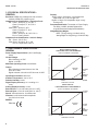
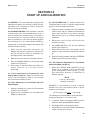
1.3 PERFORMANCE SPECIFICATIONS –
GENERAL
Power Supply Requirements: (See Load/Supply
Chart)
Lift Off Voltage:
Blind & Analog: 10 VDC
Digital: 12.5 VDC
Maximum Operating Power: 40 milliwatts
Output:
Blind & Analog: Isolated 4-20 mA into 700
ohms at 24 VDC
Digital: Isolated 4-20 mA into 575 ohms at 24 VDC
Input/Output Isolation: 600 Volts
Ambient Temperature: –30° to 70°C
Relative Humidity: 0-99%
Digital Display Accuracy: 0.1% reading ±1.0
count
Analog Display Accuracy: ±2.0%
External Zero: ±7.0% full scale (25% for 1181T)
External Span: ±7.0% full scale (50% for 1181T)
Shock: 10G maximum for 10 milliseconds
Vibration: 0.025 inches double amplitude
5 to 50 Hz for 2 hours
EMI/RFI:
EN61326
BLIND & ANALOG DISPLAY
LOAD/POWER SUPPLY REQUIREMENTS
+45 VDC @ 600 OHMS MIN. 1750 OHMS MAX.
10 VDC 24 VDC 33 VDC @ ZERO LOAD 45 VDC
LIFT OFF NOMINAL MAXIMUM
POWER SUPPLY VOLTAGE
1750 OHMS @
45 VDC
600 OHMS @
45 VDC
LOAD
RESISTANCE
REQUIRED
1.8 –
1.7 –
1.6 –
1.5 –
1.4 –
1.3 –
1.2 –
1.1 –
1.0 –
0.9 –
0.8 –
0.7 –
0.6 –
0.5 –
0.4 –
0.3 –
0.2 –
0.1 –
0.0 –
OPERATING
REGION
DIGITAL DISPLAY
LOAD/POWER SUPPLY REQUIREMENTS
+45 VDC @ 600 OHMS MIN. 1750 OHMS MAX.
12.5 VDC 24 VDC 35.5 VDC @ ZERO LOAD 45 VDC
LIFT OFF NOMINAL MAXIMUM
POWER SUPPLY VOLTAGE
1750 OHMS
@ 45 VDC
600 OHMS
@ 45 VDC
LOAD
RESISTANCE
REQUIRED
1.8 –
1.7 –
1.6 –
1.5 –
1.4 –
1.3 –
1.2 –
1.1 –
1.0 –
0.9 –
0.8 –
0.7 –
0.6 –
0.5 –
0.4 –
0.3 –
0.2 –
0.1 –
0.0 –
OPERATING
REGION

3
MODEL 1181 PB SECTION 1.0
DESCRIPTION AN SPECIFICATIONS
The Model 1181PB Transmitter measures dissolved
oxygen in parts per billion. Switch selectable ranges are
0-50, 0-100, and 0-200 ppb with air calibrate.
RECOMMENDED SENSORS:
Rosemount Analytical, La Habra, CA :
Model 120012 (P/N 639900) Rechargeable
1.4 PERFORMANCE SPECIFICATIONS @ 25°C
Measurement Range: 0-50, 0-100, & 0-200 ppb
Accuracy: ±1.0% full scale
Stability: ±1.0% full scale/month, non-cumulative
Repeatability: ±1.0 full scale
Temperature Coefficient: ±0.05 %/°C
Automatic Temperature Compensation: 0-44°C
MODEL
1181 TWO-WIRE TRANSMITTER
CODE INPUT (Required Selection)
PB Dissolved Oxygen ppb
CODE DISPLAY (Required Selection)
01 Analog display
02 Blind, without indication
06 Digital display
CODE OPTIONS
07 Two-inch pipe/wall mounting bracket
11 Stainless steel nameplate (specify marking)
CODE AGENCY APPROVALS
67 FM Explosion proof and Intrinsically Safe
69 CSA Explosion Proof and Intrinsically Safe
79 CE Construction (not available with Code 67 or 69)
1181 PB 01 07-11 67 EXAMPLE
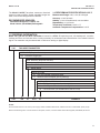
1.5 ORDERING INFORMATION
Model 1181 ppb DO Two Wire Transmitter is housed in a NEMA 7B explosion-proof, 4X weatherproof, corrosion-
resistant enclosure and includes all the circuitry necessary for measurement and transmission of an isolated 4-20 mA
signal. The transmitter may be selected with or without an analog or digital display.
NOTES:
Recommended cable from +24 volt DC power supply to Model 1181PB is Belden 8760, available from Irvine as P/N 920000; Specify length.
Model 1181PB is designed for use with Rosemount Analytical, La Habra, CA Sensor Model 120012 Rechargeable (P/N 639900) DO Sensor.

4
MODEL 1181 PB SECTION 2.0
INSTALLATION
SECTION 2.0
INSTALLATION
2.1 UNPACKING AND INSPECTION. Before opening
the shipping carton, inspect the outside of the carton
for any damage. If damage is detected, contact the
carrier immediately. If there is no apparent damage,
open the carton and inspect the instrument and
hardware. Make sure all the items in the packing list
are present and in good condition. Notify the factory if
any part is missing. If the instrument appears to be in
satisfactory condition, proceed to the transmitter
installation.
NOTE
Save the original packing cartons and
materials as most carriers require proof of
damage due to mishandling, etc., also, if it
is necessary to return the instrument to the
factory, you must pack the instrument in
the same manner as it was received. (refer
to Section 10.0 for return of materials
instructions).
2.2 MECHANICAL INSTALLATION.
IMPORTANT
Do not attempt to install and operate the
Model 1181PB without first reading this
manual.
2.2.1 General. The transmitter may be installed in
harsh environments. However, it should be installed in
an area where sources of extreme temperature
fluctuation, vibration and shock are at a minimum or
non-existent. Select an installation site that (1) is
easily accessed by operating and maintenance
personnel; (2) is at least 12 inches (300 mm) from
sources of high voltage.
2.2.2 Mounting. The transmitter may be mounted on
a flat surface using the two threaded mounting holes
located on the bottom of the transmitter or through the
use of an optional 2-inch pipe/wall mounting bracket,
Code 07 (see Figure 2-1).
2.3 HAZARDOUS LOCATIONS-EXPLOSION
PROOF INSTALLATION. In order to maintain the
explosion proof rating for the installed transmitter, the
following conditions must be met:
1. The transmitter enclosure covers must be on
hand tight and the threads must not be damaged.
NOTE
These covers seat on o-rings which
serve to provide a dust proof
enclosure for Class II and Class III
installations.
2. Explosion proof "Y" fittings must be properly
installed and plugged with a sealing compound to
prevent explosive gases from entering the
transmitter. CSA has determined that the
transmitter housing is "Factory Sealed". Instal-
lation of "Y" fittings and the use of sealing
compound is not required for CSA approved
Explosion Proof installations.
NOTE
Do not install sealing compound until
all field wiring is complete.
CAUTION
Sealing compound must be installed
prior to applying power to the
transmitter.
3. If one of the conduit connections on the housing
is not used, it must be closed with a threaded
metal plug with at least five threads engaged.
4. The serial tag cover on the external ZERO and
SPAN adjustments must be in place.
5. FM approved Explosion proof installation must be
in accordance with drawing number 1400155
(see Figure 2-2).
6. Due to the nature of the measurement, sensors
cannot be designed to meet explosion proof
certification. If the sensors must be installed in
hazardous area locations, Rosemount Analytical
Inc. recommends that an intrinsically safe system
be installed.

5
MODEL 1181 PB SECTION 2.0
INSTALLATION
2.4 WIRING-GENERAL. The transmitter is equipped
with two (2) ¼ -inch conduit openings, one on each
side of the housing. One is for the power supply/signal
wiring and the other is for the sensor wiring.
The use of waterproof cable glands or conduit is
recommended to prevent moisture from entering the
housing. If conduit is used, it should be positioned to
prevent condensation from draining into the housing.
It is recommended that the power cable/signal wiring
be shielded, twisted pairs that are earth grounded.
The transmitter case shall be grounded.
Signal or sensor wiring should never be run in the
same conduit or open tray with AC power or relay
actuated signal cables. Keep signal or sensor wiring
at least 12 inches from heavy electrical equipment.
NOTE
For best EMI/RFI protection the power
supply/signal cable should be shielded and
enclosed in an earth grounded, rigid metal
conduit. Connect the cable’s outer shield to
the transmitter’s earth ground terminal near
TB1, Fig. 2-3.
The sensor cable should also be shielded.
The cable’s outer shield shall be connected to
the transmitter’s earth ground per the
instructions above. If the sensor’s outer shield
is braided, an appropriate metal cable gland
fitting may be used to connect the braid to
earth ground via the instrument case.
A new addition to the suite of tests done to
ensure CE compliance is IEC 1000-4-5. This
is a surge immunity test that simulates
overvoltages due to switching and lightning
transients.
In order to meet the requirements of this test,
additional protection must be added to the
instrument in the form of a Transient Protector
such as the Rosemount Model 470D. This is a
3½-inch tube with ½-inch MNPT threads on
both ends. Inside the tube are gas discharge
and zener diode devices to limit surges to the
transmitter from the current loop. No
additional protection is needed on the sensor
connections.
2.4.1 Sensor Wiring. The Sensor wiring terminals are
located on the side of the housing designated TERM
SIDE on the serial label. Remove the housing cover
from the TERM SIDE to gain access to the terminals
designated TB2. Remove the optional Analog or
Digital display. The plug in analog display is held in by
a spring clip and the digital display is held in by a
locking screw. Connect the sensor wiring to TB2
terminals 1 through 4 as shown in Figure 2-3.
The Model 120012 dissolved oxygen sensor is
connected to the 1181 transmitter via a six (6)
conductor cable (PN 70000-04) as shown in Figure 2-3.
Prepare the unfinished (transmitter) end of the sensor
cable, as shown in Figure 2-3, then wire the sensor to
the transmitter per the following Steps:
1. Connect the connector end of the cable to the PB
sensor.
2. Ensure that the transmitter end of the cable has
been properly prepared with the green and yellow
wires removed and spade lugs attached. Insert
the cable through the conduit opening opposite
the external zero and span screws. This side
MUST be used due to the large size of the cable.
2.4.2 Power and Signal Wiring. The power and
signal wiring terminals are located directly above
the Sensor wiring terminals and are designated
TB1 (see Figure 2-3). TB1 also provides for
plugging in the optional Analog display or wiring
of the optional digital display.
2.5 HAZARDOUS LOCATIONS-INTRINSICALLY
SAFE INSTALLATION. To secure and maintain
intrinsically safe installation for the appropriate
approval agency, the following conditions must be
met:
1. Code 67 must be specified when ordering F.M.
units. Approved “Entity” installation must be in
accordance with Drawing Number 1400153 (see
Figure 2-4).
2. Code 69 must be specified when ordering CSA
(Canadian Standards Association) units.
Installation must be performed in accordance with
Drawing Number 1400157 (see Figure 2-5).

6
2.6 DISSOLVED OXYGEN SENSOR. The sensor
should be installed in San environment where the
temperature remains between 0 and 44°C (32-110°F).
It is used in combination with the 627866 flow
chamber and should be mounted as described in the
following sections.
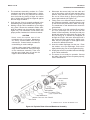
2.6.1 Installation Procedure. The sensor is shipped
assembled and charged, ready for use. Occasionally,
however, a new sensor may perform unsatisfactorily
upon initial start-up, because of previous long storage
or other unusual circumstances. If this occurs, the
sensor must be recharged as explained in Section 8.3.
During subsequent routine operation, the sensor will
require periodic recharging, typically about once every
three months. Outline and mounting dimensions of the
flow chamber are given in Figure 2-6.
2.6.2 Monitoring Boiler Feedwater or Other High-
Purity Water. The flow chamber may be mounted
behind the panel of a water quality system, or in the
plant, near the sample point.
1. Mount the flow chamber horizontally, with the
outlet port facing upward. Thus, upon start-up,
any gas bubbles will be rapidly purged. Mounting
the flow chamber horizontally also prevents
entrapment of gas bubbles on the surface of the
sensor membrane.
2. A siphon-breaker vent should be installed in the
outlet line so that the flow chamber will remain full
of water during boiler shutdowns (see Figure 2-7).
3. The sensor is installed in the flow chamber with
adaptor (P/N 193523) and safety clamp (see
Figure 2-6).
4. Sample Temperature and Flow Requirements.
Preferably, the flow chamber should receive
sample that has been temperature-conditioned to
25°C ±1°C. If this is not possible, use water-
cooled sample with the temperature held constant
to ±5°C.
2.6.3 Monitoring Deaerated Sea Water. In the multi-
stage flash vaporization process for desalinization of
sea water, feedwater is deaerated prior to entry into
the evaporators. Because of the highly corrosive
effect of oxygenated sea water, the deaeration
efficiency should be monitored continuously.
Installation of the flow chamber is essentially the
same as for monitoring boiler feedwater, as described
in Section 2.6.2.
2.6.4 Monitoring Deoxygenated Brine for Oil Well
Flooding. In oil well flooding, large volumes of brine
are pumped underground to replace oil and brine
removed during the oil production operation.
To prevent excessive corrosion of equipment, the
brine is deoxygenated prior to pumping underground.
Use of the Model 1181PB DO is essentially the same
as the boiler feedwater and desalinization applications
previously described. However, the brine may contain
metallic sulfides which may form a coating on the
oxygen sensor, thus requiring more frequent sensor
maintenance than in the other applications.
A typical sampling system is shown in Figure 2-7.
Sample for the flow chamber is obtained via a tap in
the piping on the discharge side of the flooding pump.
A needle valve is used to regulate sample flow.
Installation of a flowmeter in the sample line is usually
impractical because of the coating problem. Instead,
flow is measured by allowing the discharge from the
chamber to flow into a graduated cylinder for a timed
interval. Recommended flow rate is approximately 500
milliliters per minute.
MODEL 1181 PB SECTION 2.0
INSTALLATION

7
FIGURE 2-1 Mounting and Dimensional Drawing
MODEL 1181 PB SECTION 2.0
INSTALLATION

8
MODEL 1181 PB SECTION 2.0
INSTALLATION
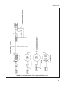
FIGURE 2-2. Schematic System, F.M. Explosion Proof Approved
DWG. NO. REV.
1400155 C

9
MODEL 1181 PB SECTION 2.0
INSTALLATION
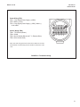
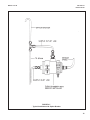
FIGURE 2-3. Transmitter Wiring
Power Wiring (TB1)
TB1-1, Loop Signal [Power Supply (+)VDC]*
TB1-2, Meter (+) Red
TB1-3, Loop Signal [Power Supply (-) VDC]* /Meter (-)
* 4-20 mADC
Sensor Wiring (TB2)
TB2-1 TC Element (Brown)
TB2-2 Shield
TB2-3, Gold Cathode (Black) and T. C. Element (Blue)
TB2-4, Silver Anode (Red)
Note: The white and green wires of the sensor cable are not used
and should be cut back away from the terminal connections of the
1181.

10
MODEL 1181 PB SECTION 2.0
INSTALLATION
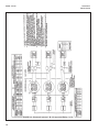
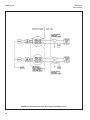
FIGURE 2-4. Schematic System, F.M. I.S. Approved-Entity (1 of 3)

11
MODEL 1181 PB SECTION 2.0
INSTALLATION
FIGURE 2-4. Schematic System, F.M. I.S. Approved-Entity (2 of 3)

12
MODEL 1181 PB SECTION 2.0
INSTALLATION
FIGURE 2-4. Schematic System, F.M. I.S. Approved-Entity (3 of 3)

13
MODEL 1181 PB SECTION 2.0
INSTALLATION
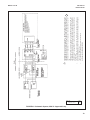
FIGURE 2-5. Schematic System, CSA I.S. Approved-Loop
DWG. NO. REV.
1400157 B
ss
3 APPROVED FOR CLASS 1, DIVISION 1, GROUPS A, B, C, D WHEN NOT USED IN CIRCUIT WITH TWO CSA
CERTIFIED SINGLE CHANNEL SAFETY BARRIERS (OF LIKE POLARITY) ONE WITH APPROVED SAFETY
PARAMETERS OF 28 VOLTS OR LESS AND 300 OHMS OR MORE IN PLUS POWER LINE, AND ONE WITH
APPROVED SAFETY PARAMETERS OF 10 VOLTS OR LESS AND 47 OHMS OR MORE IN PLUS OUTPUT
LINE.
APPROVED FOR CLASS 1, DIVISION 1, GROUPS C & D WHEN USED IN CIRCUIT WITH TWO CSA
CERTIFIED SINGLE CHANNEL SAFETY BARRIERS (OF LIKE POLARITY), ONE WITH APPROVED SAFETY
PARAMETERS OF 30 VOLTS OR LESS AND 150 OHMS OR MORE IN PLUS POWER LINE, AND ONE WITH
APPROVED SAFETY PARAMETERS OF 10 VOLTS OR LESS AND 47 OHMS OR MORE IN PLUS
OUTPUT LINE.
2. SENSOR ASSEMBLIES IN THIS SYSTEM ARE LOW ENERGY NON INCENTIVE DEVICES WHICH DO
NOT CONTAIN MAKE/BREAK CONTACTS OR COMPONENTS WHICH PRODUCE OR STORE MORE
THAN 1.2V, 0.1A, 25mW OR 20 µJ.
1. ANY CHANGE TO THIS DRAWING MAY AFFECT CSA APPROVAL
NOTES: UNLESS OTHERWISE SPECIFIED
u
B

14
MODEL 1181 PB SECTION 2.0
INSTALLATION
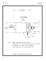
FIGURE 2-6. Flow Chamber with Sensor Dimensions

15
MODEL 1181 PB SECTION 2.0
INSTALLATION
FIGURE 2-7
. Typical Installation with Siphon Breaker

16
MODEL 1181 PB SECTION 3.0
DESCRIPTION OF CONTROLS
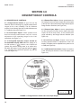
SECTION 3.0
DESCRIPTION OF CONTROLS
3.1 DESCRIPTION OF CONTROLS.
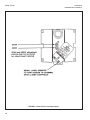
3.1.1 Range Selector Switch. A set of five (5) dip
switches used for selecting the 1181PB measurement
ranges (0-50, 0-100, 0-200PB). The Air Calibrate
position is used during Start Up, Periodic Maintenance
or Troubleshooting (see Figure 3-1).
3.1.2 Coarse Span Adjust. A 280° printed circuit
board mounted potentiometer used for coarse
adjustment of the operating range for the 1181
transmitter (see Figure 3-1).
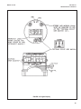
3.1.3 Analog/LCD Operation Jumper located on
the transmitter display PCB. When the jumper is in
the W5 position (• n n) position, the 1181PB will
operate only with an analog meter or as a blind unit.
But when the jumper is in the opposite position (nn
•)
or is removed, the 1181PB will operate only with an
LCD (see Figure 3-2).
3.1.4 External Zero Adjust. A 20-turn potentiometer for
fine tuning the low end current output value with respect
to the low end of the measurement range selected by the
Range Selector Switches (see Figure 3-3).
3.1.5 External Span Adjust. A 20-turn potentiometer
for fine tuning the full scale current output value with
respect to the full scale value of the measurement
range selected by the Range Selector Switches (see
Figure 3-3).
3.1.6 LCD Zero and Span. Printed circuit board
mounted potentiometers for adjustment of the LCD
display. The display can be adjusted for any value from 0
to 1999 (see Figure 3-4).
3.1.7 LCD Decimal Point Switch. Switch for selection
of the decimal point location on the LCD display (see
Figure 3-4).
FIGURE 3-1. Range Selector Switch and Course Span Adjust
DWG. NO. REV.
32968-00 A
Page is loading ...
Page is loading ...
Page is loading ...
Page is loading ...
Page is loading ...
Page is loading ...
Page is loading ...
Page is loading ...
Page is loading ...
Page is loading ...
Page is loading ...
Page is loading ...
Page is loading ...
Page is loading ...
Page is loading ...
Page is loading ...
Page is loading ...
Page is loading ...
Page is loading ...
Page is loading ...
-
 1
1
-
 2
2
-
 3
3
-
 4
4
-
 5
5
-
 6
6
-
 7
7
-
 8
8
-
 9
9
-
 10
10
-
 11
11
-
 12
12
-
 13
13
-
 14
14
-
 15
15
-
 16
16
-
 17
17
-
 18
18
-
 19
19
-
 20
20
-
 21
21
-
 22
22
-
 23
23
-
 24
24
-
 25
25
-
 26
26
-
 27
27
-
 28
28
-
 29
29
-
 30
30
-
 31
31
-
 32
32
-
 33
33
-
 34
34
-
 35
35
-
 36
36
-
 37
37
-
 38
38
-
 39
39
-
 40
40


Emerson PB Series Owner's manual
- Category
- Oxygen Equipment
- Type
- Owner's manual
- This manual is also suitable for
Ask a question and I''ll find the answer in the document
Finding information in a document is now easier with AI
Related papers
-
Rosemount 430 Dissolved Oxygen Sensor Owner's manual
-
-
-
-
-
Emerson 5081-T User manual
-
Rosemount 399VP General Purpose pH Sensor User manual
-
-
-
Other documents
-
DampRid FG83K Installation guide
-
 Hach Polymetron 9582sc User manual
-
-
-
Powers HydroGuard Thermometers Installation guide
-
Emerson Process Management 430 DO User manual
-
-
3M Monosignal 2-Pin PCB Important information
-
Omega SBG54803 Owner's manual
-
