TT
TT
T
o Go Into Programmingo Go Into Programming
o Go Into Programmingo Go Into Programming
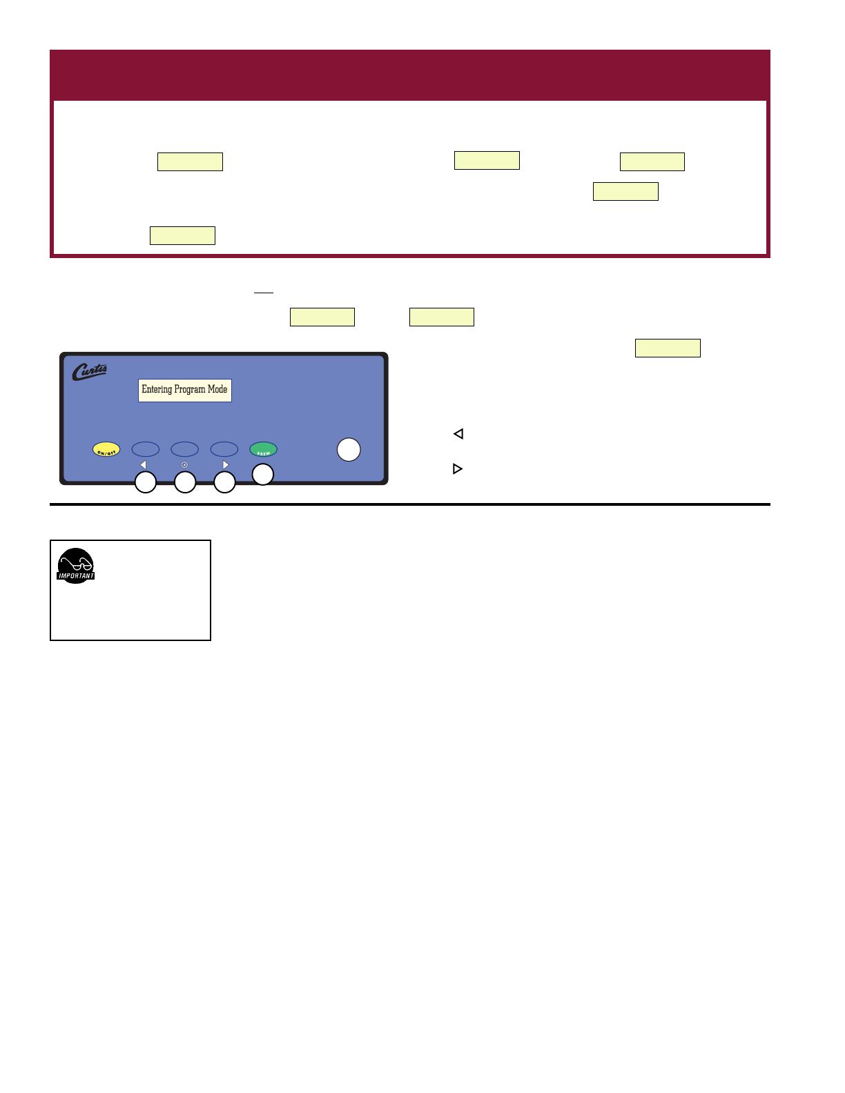
o Go Into Programming
Press
ON/OFFON/OFF
ON/OFFON/OFF
ON/OFF button (yellow). Press and hold
BREWBREW
BREWBREW
BREW button (green) and then press and release
ON/OFFON/OFF
ON/OFFON/OFF
ON/OFF button (yellow).
Continue holding
BREW BREW
BREW BREW
BREW button. Display will read , wait until is displayed Enter the 4-digit access code, the digits 1-4
correspond to the buttons (see illustration below).
The default code set at the factory is 1-2-3-4. Then will be
displayed.
Brew Volume (Factory Set at 60 oz)Brew Volume (Factory Set at 60 oz)
Brew Volume (Factory Set at 60 oz)Brew Volume (Factory Set at 60 oz)
Brew Volume (Factory Set at 60 oz)
Selecting
Brew by Volume Brew by Volume
Brew by Volume Brew by Volume
Brew by Volume or
Brew by Time Brew by Time
Brew by Time Brew by Time
Brew by Time depends on whether you know your brew time before starting.
From Program Menus press
>>
>>
> display will now show the next feature.
Brew by Brew by
Brew by Brew by
Brew by
VV
VV
V
olumeolume
olumeolume
olume: Press to Select, Display will now show Push START To Begin... Press the
BREWBREW
BREWBREW
BREW button then hot water
starts running, when desired volume is reached press
BREWBREW
BREWBREW
BREW button again to stop the flow. Now the volume has been set.
Pressing
>>
>>
> button will display the subsequent menu features.
Next item in the sequence is
Brew by Time.Brew by Time.
Brew by Time.Brew by Time.
Brew by Time. Press to Select to change the brew time. Display will now show the current
time. By pressing
<<
<<
< or
>>
>>
> you can toggle back and forth from minutes to seconds to exit (ex). Change the time or set and exit by
pressing .
TT
TT
T
emperaempera
emperaempera
empera
ture (Fture (F
ture (Fture (F
ture (F
actoractor
actoractor
actor
y set 200y set 200
y set 200y set 200
y set 200°
F)F)
F)F)
F)
Press to Select. Press
<<
<<
< or
>>
>>
> to move to desired temperature and then to set. Temperature is programmable from 170ºF to 204ºF in 2-degree increments.
Energy Save Mode (Factory seting OFF)Energy Save Mode (Factory seting OFF)
Energy Save Mode (Factory seting OFF)Energy Save Mode (Factory seting OFF)
Energy Save Mode (Factory seting OFF)
Press to Select,
<<
<<
< or
>>
>>
> ON or OFF, to set. When on, temperature is at 140ºF. Also, when enabled unit will automatically shut off 4 hours from last brew. When
feature is OFF, unit does not have the energy saving mode. This feature will save a considerable amount of energy by not heating the tank during periods of non-operation
(tank temperature maintains at 140º F).
Brew Count Odom.Brew Count Odom.
Brew Count Odom.Brew Count Odom.
Brew Count Odom.
Press to display total brew cycles. Press
exex
exex
ex or Reset
Freshness Timer (Factory set Disable)Freshness Timer (Factory set Disable)
Freshness Timer (Factory set Disable)Freshness Timer (Factory set Disable)
Freshness Timer (Factory set Disable)
Press to Select,
<<
<<
< to Off, or select
>>
>>
> to set from 20 minutes to 120 minutes in 10 minute increments, to set.
Brew Count Brew Count
Brew Count Brew Count
Brew Count
TT
TT
T
otalotal
otalotal
otal
Press to Select, Shows total gallons and total brew cycles on the unit. Not resettable.
Cold Brew Lock . . . (Factory set Delta 3)Cold Brew Lock . . . (Factory set Delta 3)
Cold Brew Lock . . . (Factory set Delta 3)Cold Brew Lock . . . (Factory set Delta 3)
Cold Brew Lock . . . (Factory set Delta 3)
Press to select,
<<
<<
< or
>>
>>
> to select desired setting (CBL 5, 15 or OFF), to set.
The CBL feature allows the brewer to brew at three different temperature levels from the actual set point. The first setting is within 5 degrees of set point, next is within
15 degrees of set point, OFF is within 30 degrees of set point for the Ready to Brew message, however it will brew at any temperature. This feature will operate after
initialization to set temperature after the rear standby toggle switch is reset to ON.
Master ResetMaster Reset
Master ResetMaster Reset
Master Reset
Press to display
Are Are
Are Are
Are
YY
YY
Y
ou Sure?ou Sure?
ou Sure?ou Sure?
ou Sure?
Then
<<
<<
< for
YY
YY
Y
eses
eses
es,
>>
>>
> for
NoNo
NoNo
No.
Brewer factory defaults are then reset.
Service Call (Phone number)Service Call (Phone number)
Service Call (Phone number)Service Call (Phone number)
Service Call (Phone number)
Press to display number and change number or
<<
<<
< to move place and EX to exit when complete This number will be displayed during a Heating system SENSOR
ERROR or during a WATER ERROR.
PROGRAM MENUS
2
During actual brew cycle
a 2-minute drip mode is
added to the brew time.
The programmed water
level compensates for back to
back brewing in Delta 3 to allow for
an increase of water volume.
YY
YY
Y
our Curtis our Curtis
our Curtis our Curtis
our Curtis
ADS System is FADS System is F
ADS System is FADS System is F
ADS System is F
actoractor
actoractor
actor
y Pre-Set for Optimum Py Pre-Set for Optimum P
y Pre-Set for Optimum Py Pre-Set for Optimum P
y Pre-Set for Optimum P
erformance.erformance.
erformance.erformance.
erformance.
After connection to water and power; the rear toggle switch must be on. You will hear a beep sound, indicating power is available to the controller.
The control displays . Press ON/OFF button and the screen will display . After three seconds,
is displayed.
Water will fill the tank (approximately 2-3 minutes depending on water flow rate). When the proper level is reached
will appear on the
screen.
Control will display when temperature reaches the setpoint (200°F). Unit is now ready to brew.
<ALP3/4/5>
WILBUR CURTIS
WILBUR CURTIS
WILBUR CURTIS
FILLING
WILBUR CURTIS
HEATING
ENTER CODE
– – – –
PROGRAM MENUS
< SELECT >
WILBUR CURTIS
READY TO BREW
ENTERING PROGRAM
MODE
D500 GT
Quick Start
1 2 3
4
All programming selections are performed with the three center buttons.
The symbols below the buttons are:
Scroll LEFT
SELECTION or ENTER to save new parameter
Scroll RIGHT
ExitExit
ExitExit
Exit Press to select, exits program mode and returns unit to operation.


