Page is loading ...

These instructions are a guide
to assembling and using
barbecue models
Premium 321S, Premium 323,
Premium 325, Premium 326,
Premium 326X, Premium 327,
Professional 529,
Professional 584.
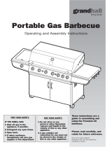
Please read carefully, and
retain for future reference.
Only to be used outdoors. Illustration may
vary from barbecue contained in carton.
FOR YOUR SAFETY.
1. Do not store or use
petrol or other flammable
vapours and liquids in the
vicinity of this or any other
appliance.
2. A gas cylinder not
connected for use must not
be stored in the vicinity of
this or any other appliance.
FOR YOUR SAFETY.
IF YOU SMELL GAS:
1. Shut off gas to the
appliance, if possible.
2. Extinguish any open flame.
3. Open hood.
4. If odour continues,
immediately call your gas
supplier or fire department.
Operating and assembly instructions
Portable Gas
Barbecues

GENERAL INFORMATION
2
2
The following minimum clearances from combustible materials must be
maintained when barbecue is in use:
top – 1000 mm, rear – 450 mm, sides – 250 mm.
Openings at the rear and sides of the appliance provide air for
combustion and must not be obstructed.
CLEARANCES
General Information 2
Safety 3-5
Pre-Assembly 6
Assembly: Premium 321S, 323, 325 models 7-11
Assembly: Premium 326, 326X, 327, Professional 529 models 12-17
Assembly: Professional 584 model 18
Operation: General 19-22
Premium 321S, 323, 325, 326, 326X, 327 models 24
Assembly: Professional 529 model 24
Assembly: Professional 584 model 25
Fault Finding 28
Maintenance 29-31
Contacts 32
TABLE OF CONTENTS
Height – All models: hood closed 1215 mm, hood open 1590 mm
Width – Premium 321S, 323, 325 models: 1462 mm
Premium 326, 326X, 327, 329, 325 models: 1690 mm
Professional 529 model: 1690 mm
Professional 584 model: 2070 mm
Depth – All models: hood closed 660 mm, hood open 720 mm
OVERALL DIMENSIONS
Appliance specifications can be found on the data label attached to the side
panel of the barbecue body.
SPECIFICATIONS
This appliance is certified to AS 4557 by the Australian Gas Association.
Barbecues must be used in accordance with the installation
requirements of your local gas supply authority, and the appropriate
installation standard AS5601.
GAS INSTALLATION CODES
5
/8"-18 UNF (
3
/8" SAE FLARE).
HOSE CONNECTIONS
The regulator and hose assembly supplied with the barbecue are suitable
for use with bottled gas – POL connection.
This regulator is adjusted to have an outlet pressure of 2.75 kPa for
connection to a gas cylinder only. The regulator and hose assembly supplied
with the appliance must be used. Replacement regulator and hose
assemblies must be those specified by the appliance manufacturer.
When connecting the hose and regulator assembly to the gas cylinder,
take care to avoid unnecessary twisting of the flexible hose. Also, take
care to avoid a loose connection with the gas cylinder. After the assembly
has been secured, turn on the gas and check for leaks by brushing a liquid
detergent and water solution over all visible and accessible gas line
connections. Include checking those connections which were made by your
supplier. The presence of bubbles will indicate a gas escape. DO NOT
TEST FOR GAS ESCAPES WITH AN OPEN FLAME. If you
are unable to correct the leak by tightening the connections, turn
off the gas and contact your place of purchase immediately.
Always ensure the appliance is kept away from flammable materials
and the gas cylinder clear of any heat source. When changing over from
an empty gas cylinder to a full one, make sure this procedure is carried
out in a flame free atmosphere.
Inspect the gas hose assembly when exchanging the gas cylinder,
or at least once a year, whichever is more frequent. If the ‘O-Ring’ or PVC
hose is cracked, cut, abraded or damaged in any way, the appliance must not
be operated. The complete assembly must be replaced if damaged and
when statutory conditions require it. Contact your place of purchase if
uncertain.
HOSE AND REGULATOR SAFETY
NEVER OPERATE THIS BARBECUE
WITHOUT A REGULATOR.
• FAILURE TO COMPLY WITH THESE
INSTRUCTIONS COULD RESULT IN A FIRE
OR EXPLOSION WHICH COULD CAUSE
SERIOUS BODILY INJURY, DEATH OR
PROPERTY DAMAGE
• ACCESSIBLE PARTS MAY BE VERY HOT
• KEEP YOUNG CHILDREN AWAY
• ANY MODIFICATION OF THIS
APPLIANCE MAY BE DANGEROUS
• DO NOT MOVE THIS APPLIANCE
DURING USE
• TURN OFF THE GAS SUPPLY AT THE GAS
CYLINDER AFTER USE
• READ THE INSTRUCTIONS BEFORE USING
THE APPLIANCE
• PARTS SEALED BY THE MANUFACTURER
MUST NOT BE ALTERED IN ANY WAY
• THIS BARBECUE IS ONLY TO BE
USED OUTDOORS.
Purchased from
Date purchased
Serial No.
NOTE:
Sales docket must be kept as proof of purchase date.
Barbecues for use with bottled gas are labelled ‘Universal LPG’ or
‘Propane’. Barbecues for use with natural gas are labelled ‘Natural Gas’
and must be installed by an authorised person. Check the gas type sticker
attached to the barbecue. Check that the label matches the gas type to
be used.
Your barbecue is preset at the factory to operate on bottled gas only,
unless specified otherwise.
FOR CUSTOMER REFERENCE
(Record and file in a safe place)

SAFETY
3
3
FOR YOUR SAFETY:
• DO NOT STORE OR USE PETROL OR
OTHER FLAMMABLE VAPOURS AND
LIQUIDS IN THE VICINITY OF THIS OR ANY
OTHER APPLIANCE.
• DO NOT STORE EMPTY OR FULL SPARE
GAS CYLINDERS UNDER OR NEAR THIS
OR ANY OTHER APPLIANCE.
• KEEP THE GAS HOSE AWAY FROM HOT
SURFACES. PROTECT GAS HOSE FROM
DRIPPING GREASE.
AVOID UNNECESSARY TWISTING OF
HOSE. VISUALLY INSPECT HOSE PRIOR
TO EACH USE FOR CUTS, CRACKS,
EXCESSIVE WEAR OR OTHER DAMAGE.
REPLACE HOSE, IF NECESSARY.
• NEVER TEST FOR GAS LEAKS WITH A LIT
MATCH OR OPEN FLAME.
• NEVER LIGHT BARBECUE WITH LID ON OR
HOOD CLOSED.
• NEVER LEAN OVER COOKING
SURFACE WHILE LIGHTING BARBECUE.
• USE GOOD QUALITY INSULATED OVEN
MITTS WHEN OPERATING BARBECUE.
• NEVER ALTER OR MODIFY THE
REGULATOR OR GAS SUPPLY ASSEMBLY.
• THIS BARBECUE MUST NOT BE USED
INDOORS.
DANGER – IF YOU SMELL OR HEAR
THE HISS OF ESCAPING GAS FROM
THE GAS CYLINDER:
• KEEP CLEAR OF THE GAS CYLINDER.
• TURN ALL CONTROLS ON THE BARBECUE
TO ‘OFF’, IF SAFE TO DO SO.
•
EXTINGUISH ANY OPEN FLAME.
•
REMOVE LID OR OPEN HOOD.
•
IF ODOUR CONTINUES, IMMEDIATELY
CALL YOUR GAS SUPPLIER OR FIRE
BRIGADE.
READ CAREFULLY BEFORE
ASSEMBLING AND OPERATING
YOUR BARBECUE.
NEVER CONNECT AN UNREGULATED
GAS CYLINDER TO YOUR BARBECUE.
• NEVER STORE YOUR GAS CYLINDER
INDOORS.
• FOR STORAGE AND CYLINDER
EXCHANGE, DISCONNECT HOSE AT THE
CYLINDER ONLY. DO NOT DISCONNECT
HOSE FROM THE APPLIANCE.
If you store your barbecue indoors, ALWAYS disconnect and remove gas
cylinder FIRST, and store gas cylinder safely outside. Gas cylinders must
be stored outdoors in a well ventilated area out of reach of children, and
must not be stored in a building, garage or any other enclosed area.
This is a low pressure barbecue and must only be used with the hose and
regulator supplied.
Your barbecue is designed for use with a 9 kg gas cylinder. Ensure
gas cylinder conforms to Australian Standard AS2469 and is less than 10
years old, or re-certified if older than 10 years.
DO NOT CONNECT YOUR BARBECUE TO A GAS
CYLINDER LESS THAN OR EXCEEDING 9 kg CAPACITY.
GAS CYLINDER USE AND SAFETY
SERVICING
ANY OF THE FOLLOWING SIGNS MAY
INDICATE THAT THE APPLIANCE IS NOT
OPERATING PROPERLY AND MAY NEED
SERVICING:
• EXCESSIVE YELLOW FLAME.
• IRREGULAR SIZE OF FLAME
ACROSS BURNER.
• ‘POPPING’ OF FLAME.
• SOOTING.
• ABNORMAL NOISE(S).
• HISSING SOUND.
NOTE:
Before requesting service,
please refer to page 28 ‘Fault Finding’.
NOTE:
The connection to
the gas cylinder is an
‘ANTI-CLOCKWISE’ connection. Ensure the connection is
Ensure the connection
is tightened firmly. Normally
only 1-1
1
/2 threads of the hose
assembly connection should
remain visible.
The gas cylinder should be filled by a reputable gas dealer, or exchanged
at a reputable gas cylinder exchange outlet. Gas cylinders should be
visually inspected and re-qualified periodically.
Always keep gas cylinder in an upright position. Always close the
cylinder valve when the barbecue is not in use.
Do not subject the gas cylinder to excessive heat.
Direction for
tightening
Keep children away from barbecue during use and until barbecue has
cooled after you are finished. Do not allow children to operate barbecue
or to swing on handle.
PROTECT CHILDREN

SAFETY
4
4
NEVER CHECK FOR LEAKS WITH
A FLAME.
IF YOU HAVE A GAS LEAK YOU
CANNOT RECTIFY, TURN OFF THE GAS
AT THE SOURCE. CONTACT THE
MANUFACTURER OR PLACE OF
PURCHASE.
ALWAYS CHECK FOR GAS LEAKS
EACH TIME YOU USE YOUR BARBECUE.
1. Make liquid detergent solution by mixing one (1) part liquid
detergent and four (4) parts water.
2. Turn burner control(s) to ‘OFF’, then turn on gas at source.
CHECKING FOR GAS LEAKS
You should follow this procedure after any of the following:
• Not having used the barbecue for an extended period of time,
• Initial assembly of barbecue,
• Any disconnection and reconnection of hose assembly,
• Changing gas cylinder,
• Upon re-connecting gas cylinder after it has been disconnected for storage.
4 parts water
Open 1/4 - 1/2
1 part liquid
detergent
3. Apply the liquid detergent solution to all visible and accessible
gas connections, including the connection to the gas cylinder.
Bubbles will appear in the liquid detergent solution if
connections are not properly sealed. Tighten or rectify as
necessary.

The following diagrams are examples of outdoor areas.
These same principles apply to canopy or shaded cloth areas.
THIS APPLIANCE SHALL ONLY BE USED IN AN ABOVE GROUND OPEN AIR SITUATION WITH NATURAL
VENTILATION, WITHOUT STAGNANT AREAS, WHERE GAS LEAKAGE AND PRODUCTS OF COMBUSTION
ARE RAPIDLY DISPERSED BY WIND AND NATURAL CONVECTION.
ANY ENCLOSURE IN WHICH THE APPLIANCE IS USED SHALL COMPLY WITH ONE OF THE FOLLOWING:
SAFETY
5
5
• AN ENCLOSURE WITH WALLS
ON ALL SIDES, BUT AT LEAST
ONE PERMANENT OPENING AT
GROUND LEVEL AND NO
OVERHEAD COVER
• WITHIN A PARTIAL
ENCLOSURE THAT INCLUDES
AN OVERHEAD COVER AND NO
MORE THAN TWO WALLS
• WITHIN A PARTIAL
ENCLOSURE THAT INCLUDES
AN OVERHEAD COVER AND
MORE THAN TWO WALLS, THE
FOLLOWING SHALL APPLY:
(i) AT LEAST 25% OF THE TOTAL
WALL AREA IS COMPLETELY
OPEN: AND
(ii) AT LEAST 30% OF THE
REMAINING WALL AREA IS
OPEN AND UNRESTRICTED
• IN THE CASE OF BALCONIES,
AT LEAST 20% OF THE TOTAL
OF THE SIDE, BACK AND FRONT
WALL AREAS SHALL BE AND
REMAIN OPEN AND
UNRESTRICTED
• DO NOT USE YOUR BARBECUE
IN GARAGES, PORCHES,
BREEZEWAYS, SHEDS OR
OTHER ENCLOSED AREAS.
YOUR BARBECUE IS TO BE
USED OUTDOORS ONLY.
Refer below.
• THE BARBECUE IS NOT
INTENDED TO BE INSTALLED IN
OR USED ON RECREATIONAL
VEHICLES AND/OR BOATS AND
SHOULD NOT BE PLACED
ADJACENT TO OR UNDER ANY
SURFACE THAT WILL BURN.
• DO NOT OBSTRUCT THE FLOW
OF COMBUSTION AND
VENTILATION AIR AROUND
THE BARBECUE HOUSING
WHILST IN USE.
Both ends
open
30% or more in total of
the remaining wall area
is open and unrestricted
30% or more in total of
the remaining wall area
is open and unrestricted
Open side at
least 25% of total
wall area
Open side at
least 25% of total
wall area

PRE-ASSEMBLY
6
6
Premium Premium Premium Premium Premium Premium Professional Professional
321S 323 325 326 326X 327 529 584
Description Qty Qty Qty Qty Qty Qty Qty Qty
Trolley bottom shelf 1 1 1 1 1 1 1 -
Castor – with lock 4444444-
Trolley legset with panel – right 1111111-
Trolley legset with panel – left 1111111-
Trolley bracket – front 1111111-
Trolley – rear panel 1111111-
Door 1 1 1 2 2 2 2 -
Door handle 1 1 1 2 2 2 2 -
Door hinge 2 2 2 4 4 4 4 -
Barbecue head assembly 1 1 1 1 1 1 1 -
Side shelf 2 1 1 2 1 1 1 2
Side burner - 1 1 - 1 1 1 -
Grease tray 1 1 1 1 1 1 1 1
Grease tray heat shield 1 1 1 1 1 1 1 1
Grease receptacle 1 1 1 1 1 1 1 1
Trolley partition - - - - - 1 1 -
Trolley partition bracket - - - - - 1 1 -
Barbecue head / trolley assembly - - - - - 1 1 1
Grill plate 2 2 2 3 3 3 3 3
Hot plate 1 1 1 1 1 1 1 1
Secondary cooking / warming rack 1 1 1 1 1 1 1 1
CONTENTS LIST
Standard Phillips-head screwdriver.
Adjustable spanner.
TOOLS YOU WILL NEED
1. Flatten cardboard packaging and use this as a protective
work surface to assemble upon.
2. Do not tighten screws and nuts, unless directed, until trolley
is fully assembled.
ASSEMBLY TIPS
Before attempting to assemble your barbecue, check that all the
necessary parts have been included using the contents list.
Inspect barbecue and trolley parts as you proceed.
Contact your place of purchase for assistance regarding
replacement of any damaged or missing parts.
Do not assemble or operate a barbecue that appears damaged.
Check that the barbecue supplied is correct for the gas type
being used. There is a label on the side panel of the barbecue
above the gas connection. Barbecues for use with gas cylinders
are labelled
‘Universal LPG’ or ‘Propane’. Barbecues for use
with natural gas are labelled ‘Natural Gas’.
CHECK BARBECUE FOR ANY DAMAGE
BARBECUES ON TROLLEYS ARE HEAVY:
TO AVOID POSSIBLE INJURY CAUSED
WHEN MOVING THE BARBECUE AND
TROLLEY, THE BARBECUE SHOULD BE
PUSHED FORWARD, AND NOT PULLED
FROM BEHIND.
Two persons are required to assemble this appliance.
GENERAL
GAS HOSES ARE FACTORY FITTED AND
LEAK TESTED – DO NOT DISCONNECT.

ASSEMBLY
7
7
• Install the left and right trolley legs with side panel (parts
are labelled ‘L’ or ‘R’)
to trolley bottom shelf.
INSTALL TROLLEY LEGS WITH SIDE PANELS
Phillips flat-head screw
1
/4" x
1
/2"
Qty: 16
Phillips flat-head screw
1
/4" x 2"
Qty: 8
• Place the trolley bottom shelf on the cardboard work surface
with the bottom side of shelf facing up. Install the four (4)
castors onto the castor seats as shown.
INSTALL CASTORS
– Premium 321S, 323, 325 models

ASSEMBLY
8
8
• Install the trolley rear panel between rear trolley legs as
shown.
INSTALL TROLLEY REAR PANEL
• Install the trolley bracket in the up position (part is labelled
‘UP’ to ensure proper assembly) between front trolley legs
as shown.
INSTALL TROLLEY BRACKET
Phillips flat-head screw
1
/4" x
1
/2"
Qty: 4
Phillips flat-head screw
1
/4" x 2"
Qty: 4

• Install the door handle to door.
• Install the bottom door hinge bracket to right trolley leg.
• Insert door bottom post into bottom door hinge bracket.
• Hold the door and install the top door hinge bracket to right
trolley leg.
INSTALL DOOR
• Remove cooking components from barbecue head. With an
assistant, lift and position barbecue head on the trolley.
• Tighten securely using screws.
• Attach the lighting stick to the left body panel using screw.
INSTALL BARBECUE HEAD
Door handles
Phillips flat-head screw
1
/4" x
3
/4"
(Stainless steel) Qty: 2
Door hinges
Phillips-head screw
3
/16" x
3
/8"
Qty: 4
Lighting stick to barbecue body
Phillips-head screw M4 x 8 mm
Qty: 1
Barbecue body to trolley
Phillips flat-head screw
1
/4" x 1
3
/16"
Qty: 4
Lighting stick
Qty: 1
ASSEMBLY
9
9
Lighting Stick

ASSEMBLY
10
10
Premium
323 / 325
Premium
321S
Tool holder to side shelf
Phillips-head screw
M5 x 8 mm
Side shelves / side burner to
barbecue head
Phillips flat-head screw
1
/4" x
3
/4"
Qty: 10
• Remove screws from the tool holder. Slide the four (4) tool
hooks onto the tool holder with the hooks facing the left
side shelf. Attach tool holder to side shelf using these
screws.
• Align the two (2) holes on front and rear body panels and
three (3) holes on left body panel with the threaded holes
on left side shelf. Insert the three (3) screws from the
inside of the barbecue body and tighten securely.
• Align the two (2) holes on underside of left side shelf with
the threaded holes on left body panel. Insert the two (2)
screws and tighten securely.
• Repeat for right side burner frame
(right side shelf).
INSTALL SIDE SHELF AND
SIDE BURNER FRAME
(Premium 321S model has two side shelves)
Inner side view of
left side shelf
Inner side view of
Right side burner
frame (right side shelf)
NOTE: For Premium 321S model the side shelves
may also be installed to the Premium Range and
Premium Sink/Workstation modules. Refer to the
appropriate instructions supplied with the modules.

• Remove plastic shipping bands attaching regulator to burner.
• Place the heat shield into grease draining tray making sure to
fit the heat shield tabs into the slots in the base of the tray.
• From the back of the barbecue, slide the assembled tray
side tabs over the side rails underneath the
barbecue head.
• Install grease receptacle under the
grease draining tray from the front
of barbecue.
ASSEMBLE AND INSTALL GREASE
DRAINING TRAY
ASSEMBLY
11
11
NOTE: Remove plastic protection sleeve from male
fitting before connecting side burner hose.
• Position hose socket over valve plug. See diagram A.
• Pull and hold back socket sleeve.
• Push socket to right until it firmly snaps into place over
plug.
See diagram B.
• Push sleeve to right until it fully snaps into place. See
diagram C.
• Give hose a tug to left to insure connection is secure.
WARNING:
Failure to securely connect hose
socket to valve plug may result in gas leaks which
can cause fire or explosion.
CONNECT SIDE BURNER GAS VALVE
– Premium 323, 325 models
Diagram A.
Diagram B.
Diagram C.
NOTE:
Refer above
Sleeve
Sleeve
PlugSocket

• Install the left and right trolley legs with side panel (parts
are labelled ‘L’ or ‘R’) to trolley bottom shelf.
INSTALL TROLLEY LEGS WITH SIDE PANELS
Phillips flat-head screw
1
/4" x
1
/2"
Qty: 16
Phillips flat-head screw
1
/4" x 2"
Qty: 8
ASSEMBLY
12
12
• Place the trolley bottom shelf on the cardboard work surface
with the bottom side of shelf facing up. Install the four (4)
castors onto the castor seats as shown.
INSTALL CASTORS
NOTE: Professional 529 model does not have a hole
in the base tray for the gas cylinder housing.
Assembly diagrams are representative at some
stages.
Premium 326, 326X & 327, Professional 529

Phillips flat-head screw
1
/4" x
1
/2"
Qty: 4
• Install the trolley rear panel between rear trolley legs as
shown.
INSTALL TROLLEY REAR PANEL
Phillips flat-head screw
1
/4" x
1
/2"
Qty: 4
ASSEMBLY
13
13
Install the cylinder pull-out tray to trolley bottom shelf.
INSTALL GAS CYLINDER PULL-OUT TRAY
(Professional 529 model)

• Install the trolley bracket in the up position (part is labelled
‘UP’ to ensure proper assembly) between front trolley legs
as shown.
INSTALL TROLLEY BRACKET
Phillips flat-head screw
1
/4" x 2"
Qty: 4
ASSEMBLY
14
14
NOTE: For Premium 529 model, four (4) screws to
assemble partition panel to the trolley panels are
stainless steel.
Phillips flat-head screw
1
/4" x
1
/2"
Qty: 7
• Install the left partition panel to left trolleyside panel and
trolley rear panel.
• Install the left partition panel bracket between partition
panel and trolley bottom shelf.
INSTALL LEFT PARTITION PANEL
(Not applicable to Premium 326 and 326X
models)

• Install the door handle to right door.
• Install the right bottom door hinge bracket to right trolley
leg.
• Insert right door bottom post into right bottom door hinge
bracket.
• Hold the right door and install the right top door hinge
bracket to right trolley leg.
• Repeat for left door.
• Install the door guide plate to
trolley bottom shelf.
INSTALL DOORS
Door handles
Phillips flat-head screw
1
/4" x
3
/4"
Qty: 4
• Remove cooking components from barbecue head. With an
assistant, lift and position barbecue head on the trolley.
• Tighten securely using screws.
• Attach the lighting stick to the left body panel.
INSTALL BARBECUE HEAD
Barbecue head to trolley
Phillips flat-head screw
1
/4" x 1
3
/16"
Qty: 4
Lighting stick to barbecue body
Phillips-head screw M4 x 8 mm
Qty: 1
Lighting stick
Qty: 1
ASSEMBLY
15
15
Lighting Stick
Door hinges, guide plate
Phillips-head screw
3
/16" x
3
/8"
Qty: 10

Inner side view of
right side burner
frame
Inner side view of
left side shelf
ASSEMBLY
16
16
Tool holder to side shelf
Phillips-head screw
M5 x 8 mm
Side shelves / side burner to
barbecue head
Phillips flat-head screw
1
/4" x
3
/4"
Qty: 10
• Remove screws from the tool holder. Slide the four (4) tool
hooks onto the tool holder with the hooks facing the left
side shelf. Attach tool holder to side shelf using these
screws.
• Align the two (2) holes on front and rear body panels and
three (3) holes on left body panel with the threaded holes
on left side shelf. Insert the three (3) screws from the
inside of the barbecue body and tighten securely.
• Align the two (2) holes on under side of left side shelf with
the threaded holes on left body panel. Insert the two (2)
screws and tighten securely.
• Repeat for right side burner frame
(right side shelf).
INSTALL SIDE SHELF AND
SIDE BURNER FRAME
(Premium 326X model has two side shelves)
Premium 326, 327
Professional 529
Premium
326X
NOTE: For Premium 326X model the side shelves
may also be installed to the Premium Range and
Premium Sink/Workstation modules. Refer to the
appropriate instructions supplied with the modules.

ASSEMBLY
17
17
• Remove plastic shipping bands attaching regulator to burner.
• Place the heat shield into grease draining tray making
sure to fit the heat shield tabs into the slots in the base of
the tray.
• From the back of the barbecue, slide the assembled tray
side tabs over the side rails underneath the barbecue head.
• Install grease receptacle under the grease draining
tray from the front of barbecue.
ASSEMBLE AND INSTALL GREASE
DRAINING TRAY
Diagram A.
Diagram B.
Diagram C.
Sleeve
Sleeve
PlugSocket
Premium 327 /
Professional 529
Refer above
Using a spanner connect the free end of
the factory-fitted gas hose to the side
burner to the manifold inlet. Refer to
page 4 for ‘Leak Test Procedure’.
Premium 326 model
NOTE: Remove plastic protection sleeve from male
fitting before connecting side burner hose.
• Position hose socket over valve plug. See diagram A.
• Pull and hold back socket sleeve.
• Push socket to right until it firmly snaps into place over
plug. See diagram B.
• Push sleeve to right until it fully snaps into place. See
diagram C.
• Give hose a tug to left to insure connection is secure.
WARNING:
Failure to securely connect hose socket
to valve plug may result in gas leaks which can
cause fire or explosion.
Premium 327 model, Professional 329 model
CONNECT SIDE BURNER GAS VALVE
Premium 326
Connect here

ASSEMBLY
18
18
Tool holder to side shelf
Phillips-head screw
M5 x 8 mm
Qty: 2
Side shelves / side burner to
barbecue head
Phillips flat-head screw
1
/4" x
3
/4"
Qty: 10
• Remove screws from the tool holder. Slide the four (4) tool
hooks onto the tool holder with the hooks facing the left
side shelf. Attach tool holder to side shelf using these
screws.
• Align the two (2) holes on front and rear body panels and
three (3) holes on left body panel with the threaded holes
on left side shelf. Insert three (3) screws from the inside of
the barbecue body, and tighten securely.
• Align the two (2) holes on under side of left side shelf with
the threaded holes on left body panel. Tighten securely
using two (2) screws.
• Align the five (5) holes on under side of right side shelf with
the threaded holes on right outside body panel. Tighten
securely using five (5) screws.
INSTALL SIDE SHELVES
– Professional 584 model

This test will ensure that the spark electrode tips are properly
positioned so your barbecue lights easily and properly.
WITH THE ASSISTANCE OF ANOTHER
PERSON, PERFORM THIS ELECTRODE
CHECK BEFORE PROCEEDING
ASSEMBLY – GENERAL
19
19
If no spark is seen, the spark gap needs to be
adjusted as follows:
• Using an adjustable spanner, loosen the inside nut until the
gas collector box can be turned upward. If the gap between
the spark electrode tip and receiver is more than 4 - 5 mm use
long nose pliers to gently squeeze the gas collector box to
narrow gap. Return the gas collector box to its original
position, secure the inside nut and try the electrode check
again.
If no ‘clicking’ sound is heard:
• AA battery may be installed backwards.
• Electronic wires may be loose. Remove the AA battery and
inspect the igniter junction box found behind the control
panel and reconnect any loose wires.
Ensure the gas source is turned off – or is disconnected and all
burner control knobs are set to
‘OFF’– and open the lids / side
shelves.
Have your assistant stand behind to the right of the barbecue
and look toward the front of the barbecue. Never put your face
inside the barbecue.
Press the igniter cap or turn
‘IGN’. You should hear a ‘clicking’
sound. Your assistant should see a blue spark within each gas
collector box. If a spark is present the electrode tips are properly
positioned.
• Open side burner lid. Remove plastic shipping band from
burner and pot support.
• Push and turn side burner control knob to
‘HI’ or ‘IGN’.
Look for spark between tip of electrode and burner.
• If you don't see a spark from side burner electrode, adjust
gap between electrode and burner surface to 4 - 5 mm.
SIDE BURNER ELECTRODE CHECK
• CHECK PERFORMANCE OF
BURNERS PRIOR TO INSTALLING
BARBECUE PLATE COMPONENTRY.
Refer pages 24, 25 for lighting
instructions
• DO NOT SMOKE WHEN ATTEMPTING
TO IGNITE BARBECUE
• NEVER USE VOLCANIC ROCK,
HEAT BEADS OR OTHER MATERIAL
• ALWAYS USE PROTECTIVE GLOVES
WHEN HANDLING HOT COMPONENTS.
4-5 mm spark
gap
Gas collector
box
Inside nutSpark electrode tipSpark receiver
• Unscrew igniter cap from control panel.
• Place supplied AA battery into the igniter slot with positive
pole facing you.
• Position the cap and spring over the AA battery and tighten
onto control panel.
INSTALL IGNITER BATTERIES
Spring
Igniter
cap
Contact
AA
battery

• Place the flame tamer on lower ledge above burners and
under the grill plates.
• Place grill plates and hot plates on body ledge.
• Place the secondary cooking / warming rack into the slots
on barbecue body side panels.
INSTALL COOKING COMPONENTS
ASSEMBLY – GENERAL
20
20
Grill plate
Grill plate
Slots for secondary
cooking / warming
rack
Slots for secondary
cooking / warming
rack
Hot plate
Hot plate
Pot support
Hot plate
Grill plate
Premium 321S, 323, 325 models
Premium 326, 326X, 327 and Professional 529 models
Professional 584 model
Flame tamer
Flame tamer
Flame tamer
Secondary cooking
/ warming rack
Secondary cooking
/ warming rack
Secondary cooking
/ warming rack
THIS APPLIANCE IS NOT DESIGNED
FOR THE ENTIRE COOKING SURFACE
TO BE COVERED WITH SOLID PLATES.
A HAZARDOUS SITUATION MAY BE
CREATED WHEREBY BURNERS MAY
BEGIN TO BURN TOXIC GASES, OR
EVEN GO OUT.
NOTE: For models 326, 326X, 327, 329 and 584 it is
possible to use a maximum of two hot plates.
Slots for secondary
cooking / warming
rack
/