Chauvet Rogue User manual

Category
Floodlights
Type
User manual

Chauvet Rogue: The Rogue Outcast 3 Spot is a powerful and versatile moving head fixture that combines a 300W Osram Sirius HRI lamp with a wide range of features to create stunning effects for any event or production. With its CMY + CTO color mixing system, two gobo wheels, and 7-position rotating prism, the Rogue Outcast 3 Spot can create a variety of looks from vibrant colors to sharp gobo projections.

Chauvet Rogue: The Rogue Outcast 3 Spot is a powerful and versatile moving head fixture that combines a 300W Osram Sirius HRI lamp with a wide range of features to create stunning effects for any event or production. With its CMY + CTO color mixing system, two gobo wheels, and 7-position rotating prism, the Rogue Outcast 3 Spot can create a variety of looks from vibrant colors to sharp gobo projections.

Model ID: ROGUEOUTCAST3SPOT
User Manual
Rogue Outcast 3 Spot User Manual Rev. 3
Edition Notes
The Rogue Outcast 3 Spot User Manual includes a description, safety precautions, installation,
programming, operation and maintenance instructions for the Rogue Outcast 3 Spot as of the release date
of this edition.
Trademarks
Chauvet, Chauvet Professional, the Chauvet logo, Rogue, Outcast, and Rogue Outcast are registered
trademarks or trademarks of Chauvet & Sons, LLC (d/b/a Chauvet and Chauvet Lighting) in the United
States and other countries. Other company and product names and logos referred to herein may be
trademarks of their respective companies.
Copyright Notice
The works of authorship contained in this manual, including, but not limited to, all designs, text, and images
are owned by Chauvet.
© Copyright 2023 Chauvet & Sons, LLC. All rights reserved.
Electronically published by Chauvet in the United States of America.
Manual Use
Chauvet authorizes its customers to download and print this manual for professional information purposes
only. Chauvet expressly prohibits the usage, copy, storage, distribution, modification, or printing of this
manual or its content for any other purpose without written consent from Chauvet.
Document Printing
For best results, print this document in color, on letter size paper (8.5 x 11 in), double-sided. If using A4
paper (210 x 297 mm), configure the printer to scale the content accordingly.
Intended Audience
Any person installing, operating, and/or maintaining this product should completely read through the guide
that shipped with the product, as well as this manual, before installing, operating, or maintaining this
product.
Disclaimer
Chauvet believes that the information contained in this manual is accurate in all respects. However,
Chauvet assumes no responsibility and specifically disclaims any and all liability to any party for any loss,
damage or disruption caused by any errors or omissions in this document, whether such errors or
omissions result from negligence, accident or any other cause. Chauvet reserves the right to revise the
content of this document without any obligation to notify any person or company of such revision, however,
Chauvet has no obligation to make, and does not commit to make, any such revisions. Download the latest
version from www.chauvetprofessional.com.
Document Revision
This is revision 3 of the Rogue Outcast 3 Spot User Manual. Go to www.chauvetprofessional.com for the
latest version.
Rogue Outcast 3 Spot User Manual Rev. 3
Table of Contents
i
TABLE OF CONTENTS
1. Before You Begin ....................................................................... 1
What Is Included ........................................................................................... 1
Claims ........................................................................................................... 1
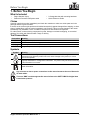
Text Conventions .......................................................................................... 1
Symbols ........................................................................................................ 1
Safety Notes.................................................................................................. 2
Personal Safety.................................................................................................. 2
Mounting and Rigging ........................................................................................ 2
Power and Wiring............................................................................................... 2
Operation ........................................................................................................... 3
FCC Statement of Compliance ..................................................................... 3
Expected LED Lifespan................................................................................. 3
2. Introduction ................................................................................ 4
Description .................................................................................................... 4
Features........................................................................................................ 4
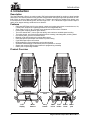
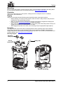
Product Overview.......................................................................................... 4
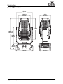
Product Dimensions ...................................................................................... 5
3. Setup ........................................................................................... 6
AC Power...................................................................................................... 6
AC Plug .............................................................................................................. 6
Power Linking..................................................................................................... 6
Fuse Replacement ............................................................................................. 6
DMX Linking.................................................................................................. 6
Remote Device Management............................................................................. 6
USB Software Update ................................................................................... 7
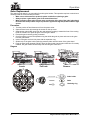
Mounting ....................................................................................................... 8
Orientation.......................................................................................................... 8
Rigging ............................................................................................................... 8
Procedure........................................................................................................... 8
4. Operation .................................................................................... 9
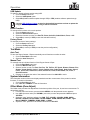
Control Panel Description ............................................................................. 9
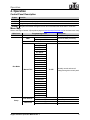
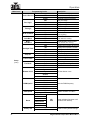
Menu Map ..................................................................................................... 9
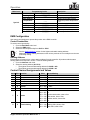
DMX Configuration........................................................................................ 11
Control Personalities .......................................................................................... 11
Starting Address................................................................................................. 11
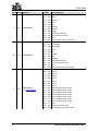
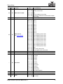
Control Channel Assignments and Values.................................................... 11
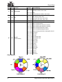
Color Wheels...................................................................................................... 14
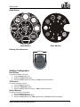
Gobo Wheels ..................................................................................................... 15
Rotating Gobo Dimensions ............................................................................................. 15
Settings Configuration................................................................................... 15
Pan Reverse ...................................................................................................... 15
Tilt Reverse ........................................................................................................ 15
Screen Reverse ................................................................................................. 15
Pan Angle........................................................................................................... 16
Tilt Angle ............................................................................................................ 16
Black Out on Movement..................................................................................... 16
Display Backlight Timer...................................................................................... 16
Table of Contents
Rogue Outcast 3 Spot User Manual Rev. 3
ii
Swap Pan and Tilt .............................................................................................. 16
DMX Loss........................................................................................................... 16
Fan Mode ........................................................................................................... 16
Dimmer Curve .................................................................................................... 16
Pulse Width Modulation ..................................................................................... 16
USB Update ....................................................................................................... 17
Reset Function ................................................................................................... 17
Factory Reset..................................................................................................... 17
Test Mode ..................................................................................................... 17
Auto Test............................................................................................................ 17
Manual Test ....................................................................................................... 17
System Information ....................................................................................... 17
Offset Mode (Zero Adjust)............................................................................. 17
Gobo Replacement ....................................................................................... 18
Procedure........................................................................................................... 18
Diagram .......................................................................................................................... 18
5. Maintenance................................................................................ 19
Product Maintenance .................................................................................... 19
6. Technical Specifications ........................................................... 20
Contact Us ...................................................................................... 21
Warranty & Returns....................................................................................... 21
1
Rogue Outcast 3 Spot User Manual Rev. 3
Before You Begin
1. Before You Begin
What Is Included
Claims
Carefully unpack the product immediately and check the container to make sure all the parts are in the
package and are in good condition.
If the box or the contents (the product and included accessories) appear damaged from shipping, or show
signs of mishandling, notify the carrier immediately, not Chauvet. Failure to report damage to the carrier
immediately may invalidate a claim. In addition, keep the box and contents for inspection.
For other issues, such as missing components or parts, damage not related to shipping, or concealed
damage, file a claim with Chauvet within 7 days of delivery.
Text Conventions
Symbols
Rogue Outcast 3 Spot
Seetronic Powerkon IP65 power cable
2 Omega brackets with mounting hardware
Quick Reference Guide
Convention Meaning
1–512 A range of values
50/60 A set of values of which only one can be chosen
Settings A menu option not to be modified
<ENTER> A key to be pressed on the product’s control panel
Symbol Meaning
Critical installation, configuration, or operation information. Not following these
instructions may make the product not work, cause damage to the product, or cause
harm to the operator.
Important installation or configuration information. The product may not function correctly
if this information is not used.
Useful information.
Any reference to data or power connections in this manual assumes the use of Seetronic
IP rated cables.
The term “DMX” used throughout this manual refers to the USITT DMX512-A digital data
transmission protocol.
2
Before You Begin
Rogue Outcast 3 Spot User Manual Rev. 3
Safety Notes
Read all the following safety notes before working with this product. These notes contain important
information about the installation, usage, and maintenance of this product.
The luminaire is intended for professional use only.
If the external flexible cable or cord of this luminaire is damaged, it shall be replaced by a special cord
or cord exclusively available from the manufacturer or its service agent.
The light source contained in this luminaire shall only be replaced by the manufacturer or its service
agent or a similar qualified person.
• CAUTION:
This product’s housing may be hot when operating. Mount this product in a location with adequate
ventilation, at least 20 in (50 cm) from adjacent surfaces.
When transferring the product from extreme temperature environments, (e.g., cold truck to warm humid
ballroom) condensation may form on the internal electronics of the product. To avoid causing a failure,
allow the product to fully acclimate to the surrounding environment before connecting it to power.
Flashing light is known to trigger epileptic seizures. User must comply with local laws regarding
notification of strobe use.
• ALWAYS:
Disconnect from power before cleaning the product or replacing the fuse.
When using an IP65-rated product in an outdoor environment, use IP65- (or higher) rated power
and data cable.
Replace and secure IP-rated protective covers to all power, data, USB, or other ports when not in
use.
Replace the fuse with the same type and rating.
Use a safety cable when mounting this product overhead.
Connect this product to a grounded and protected circuit.
•DO NOT:
Open this product. It contains no user-serviceable parts.
Look at the light source when the product is on.
Leave any flammable material within 20 cm of this product while operating or connected to power.
Connect this product to a dimmer or rheostat.
Operate this product if the housing, lenses, or cables appear damaged.
Submerge this product (adhere to standards for the published IP rating). Regular outdoor operation
is fine.
Permanently install outdoors in locations with extreme environmental conditions. This includes, but
is not limited to:
Exposure to a marine/saline environment (within 3 miles of a saltwater body of water).
Locations where normal temperatures exceed the temperature ranges in this manual.
Locations that are prone to flooding or being buried in snow.
Other areas where the product will be subject to extreme radiation or caustic substances.
ONLY use the handles or the hanging/mounting brackets to carry this product.
The maximum ambient temperature is 113 °F (45 °C). Do not operate this product at higher temperatures.
The minimum startup temperature is -4°F (-20°C). Do not start the product at lower temperatures.
The minimum ambient temperature is 14°F (-10°C). Do not operate the product at lower temperatures.
To eliminate unnecessary wear and improve its lifespan, during periods of non-use completely
disconnect the product from power via breaker or by unplugging it.
In the event of a serious operating problem, stop using immediately.
This product contains no user-serviceable parts. Any reference to servicing in this User
Manual will only apply to properly trained, certified technicians. Do not open the housing
or attempt any repairs.
All applicable local codes and regulations apply to proper installation of this product.
If a Chauvet product requires service, contact Chauvet Technical Support.
3
Rogue Outcast 3 Spot User Manual Rev. 3
Before You Begin
FCC Statement of Compliance
This device complies with Part 15 Part B of the FCC rules. Operation is subject to the following two
conditions:
1. This device may not cause harmful interference, and
2. This device must accept any interference received, including interference that may cause
undesired operation.
This equipment has been tested and found to comply with the limits for a Class B digital device, pursuant
to Part 15 of the FCC Rules. These limits are designed to provide reasonable protection against harmful
interference in a residential installation. This equipment generates uses and can radiate radio frequency
energy and, if not installed and used in accordance with the instructions, may cause harmful interference
to radio communications. However, there is no guarantee that interference will not occur in a particular
installation. If this equipment does cause harmful interference to radio or television reception, which can be
determined by turning the equipment off and on, the user is encouraged to try to correct the interference by
one or more of the following measures:
Reorient or relocate the receiving antenna.
Increase the separation between the equipment and receiver.
Connect the equipment into an outlet on a circuit different from that to which the receiver is
connected.
Consult the dealer or an experienced radio/TV technician for help.
Any changes or modifications not expressly approved by the party responsible for compliance could void
the user’s authority to operate the equipment.
Expected LED Lifespan
Over time, use and heat will gradually reduce LED brightness. Clustered LEDs produce more heat than
single LEDs, contributing to shorter lifespans if always used at full intensity. The average LED lifespan is
40,000 to 50,000 hours. To extend LED lifespan, maintain proper ventilation around the product, and limit
the overall intensity.
4
Introduction
Rogue Outcast 3 Spot User Manual Rev. 3
2. Introduction
Description
The Rogue Outcast 3 Spot is an outdoor-ready, IP65 moving head spot ideal for medium to large festivals
and events. This feature-packed moving spot has a bright 300 W LED light engine that produces an even
field of light, as well as rotating and static gobos, two 7-position and split-color enabled color wheels, and
five facet prism to create stunning looks. A zoom range of 4.5 – 38.1° allows the Rogue Outcast 3 Spot to
easily cover stages and large surfaces from a distance.
Features
IP65 rated LED Spot with (2) color wheels, a static and rotating gobo wheel, motorized zoom, Iris,
5 facet prism, encased in a lightweight aluminum and magnesium alloy
Zoom range of 4.5° to 38.1 to easily cover stages and surfaces from a distance
Perfect gobo morphing between gobo wheels
Two color wheels with 7 colors, split color ability, and continuous variable speed scrolling
Two gobo wheels: one fixed scrolling wheel and one rotating, interchangeable, scrolling wheel
Iris, 5-facet prism, and frost for beam control
Beautiful 16-bit LED dimming for ultimate fade control
IP65 rated power input/output connections for power linking
5-pin DMX input/output connections
RDM enabled for remote addressing and trouble shooting
Selectable PWM settings to maintain flicker free operation on camera
Simple and complex DMX channel profiles for programming versatility
USB-C port for uploading software
Product Overview
Menu
buttons
LCD
display
DMX
in/out
Carry
handle
Power
in/out
Fuse
holder
USB C
port
Condensation
valve
5
Rogue Outcast 3 Spot User Manual Rev. 3
Introduction
Product Dimensions
10.12 in
257 mm
13.46 in
342 mm
25.16 in
639 mm
17.48 in
444 mm
9.61 in
244 mm
14.41 in
366 mm
9.5 in
241 mm
13.9 in
353 mm
4.23 in
107 mm
6
Setup
Rogue Outcast 3 Spot User Manual Rev. 3
3. Setup
AC Power
The Rogue Outcast 3 Spot has an auto-ranging power supply and it can work with an input voltage range
of 100 to 240 VAC, 50/60 Hz.
To determine the product’s power requirements (circuit breaker, power outlet, and wiring), use the current
value listed on the label affixed to the product’s back panel, or refer to the product’s specifications chart.
The listed current rating indicates the product’s average current draw under normal conditions.
AC Plug
The Rogue Outcast 3 Spot comes with a power input cable terminated with a Seetronic Powerkon A
connector on one end and bare wire on the other end (U.S. market). Use the table below to wire a plug.
Power Linking
It is possible to power link Rogue Outcast 3 Spot products. See the table below for the current draw at each
voltage and frequency:
Never exceed 12A on a single circuit. Power-linking cables can be purchased separately.
Fuse Replacement
1. Disconnect this product from the power outlet.
2. Using a flat-head screwdriver, unscrew the fuse holder cap from the housing.
3. Remove the blown fuse and replace with another fuse of the same type and rating (F 8 A, 250 V).
4. Screw the fuse holder cap back in place and reconnect power.
DMX Linking
The Rogue Outcast 3 Spot will work with a DMX controller using a 5-pin DMX serial connection. A DMX
Primer is available from www.chauvetprofessional.com.
Remote Device Management
Remote Device Management, or RDM, is a standard for allowing DMX-enabled devices to communicate
bi-directionally along existing DMX cabling. Check the DMX controller’s User Manual or with the
manufacturer as not all DMX controllers have this capability. The Rogue Outcast 3 Spot supports RDM
protocol that allows feedback to make changes to menu map options.
Always connect the product to a protected circuit (a circuit breaker or fuse). Make sure
the product has an appropriate electrical ground to avoid the risk of electrocution or
fire.
To eliminate unnecessary wear and improve its lifespan, during periods of non-use
completely disconnect the product from power via breaker or by unplugging it.
Never connect the product to a rheostat (variable resistor) or dimmer circuit, even if the
rheostat or dimmer channel serves only as a 0 to 100% switch.
Connection Wire (U.S.) Wire (Europe) Screw Color
AC Live Black Brown Yellow or Brass
AC Neutral White Blue Silver
AC Ground Green/Yellow Green/Yellow Green
100 V, 60 Hz 120 V, 60 Hz 208 V, 60 Hz 230 V, 50 Hz 240 V, 60 Hz
Current Draw 8.2 A8.8 A8.4 A9.6 A9.2 A
7
Rogue Outcast 3 Spot User Manual Rev. 3
Setup
USB Software Update
The Rogue Outcast 3 Spot allows for software update through USB using the built-in USB port. To update
the software using a USB type C flash drive, do the following:
1. Power on the fixture and plug the flash drive into the USB port.
2. Once the flash drive has been detected, the message “USB UPDATE” will be displayed. Press
<YES>.
3. The next screen will show the software versions available for this fixture on the USB drive. For
multiple versions of the software for the same fixture, use <UP> or <DOWN> to select the desired
version. Press <ENTER>.
4. The “USB UPDATE” screen will re-appear. Press <YES>
5. The updgrade will start. DO NOT turn off the power or disconnect the USB while the USB LED is
still blinking during the process. The screen display will read: “USB UPDATE WAIT”. USB update
can take several minutes to complete.
6. Go to the Fixture Information on the product's menu map and confirm the firmware revision
7. When the boot-up process is finished, restart the product.
When the USB stops blinking, all the motors will power down and the display will go
blank. DO NOT turn off the power. The fixture will automatically reboot when the update is
done.
Place the .chl file in the root directory of the USB drive.
The product's USB port supports up to 32GB capacity and only works with FAT32 file format.
Turning off the power or removing the USB while still blinking during the update will
cause partial or total firmware failure in the targeted fixture(s). If this occurs, the user will
need the UPLOAD 08 device to fix this. Please contact Chauvet regarding this device.
8
Setup
Rogue Outcast 3 Spot User Manual Rev. 3
Mounting
Before mounting the product, read and follow the safety recommendations indicated in the Safety Notes.
For our Chauvet Professional line of mounting clamps, go to http://trusst.com/products/.
Orientation
Always mount this product in a safe position, making sure there is adequate room for ventilation,
configuration, and maintenance.
Rigging
Chauvet recommends using the following general guidelines when mounting this product.
Before deciding on a location for the product, make sure there is easy access to the product for
maintenance and programming purposes.
Make sure that the structure and attachment points can support the weight before hanging the
product (see the Technical Specifications for weight information).
When mounting the product overhead, always use a safety cable. Mount the product securely to a
rigging point, whether an elevated platform or a truss.
When rigging the product onto a truss, use a mounting clamp of appropriate weight capacity.
Procedure
The Rogue Outcast 3 Spot comes with 2 omega brackets to which mounting clamp can be attached
directly. Mounting clamps are (sold separately). Make sure the clamps are capable of supporting the
weight of this product. Use at least two mounting points per product. For the Chauvet Professional line of
mounting clamps, go to http://www.trusst.com/products.
Mounting Diagram
Safety cable
Mounting
clamp (x2)
Omega
bracket (x2)
Overhead mounting Surface mounting
9
Rogue Outcast 3 Spot User Manual Rev. 3
Operation
4. Operation
Control Panel Description
Menu Map
Refer to the Rogue Outcast 3 Spot product page on
www.chauvetprofessional.com
for the latest menu map.
Button Function
<MENU> Exits from the current menu or function
<ENTER> Enables the currently displayed menu or sets the selected value into the selected function
<UP> Navigates upwards through the menu list or increases the value when in a function
<DOWN> Navigates downwards through the menu list or decreases the value when in a function
Main Level Programming Levels Description
Address 001–512 Sets the starting address
Run Mode
DMX 20CH Selects the DMX personality
25CH
Auto Test Auto test all functions
Manual Test
Pan
0–255 Manually control and test all
settings through the control panel
Pan Fine
Tilt
Tilt Fine
P/T Speed
Dimmer
Dimmer Fine
Shutter
Virtual Shaking
Color1
Color2
Gobo2
Gobo
Gobo Rotate
Gobo Index
Gobo2
Focus
Focus Fine
Auto Focus
Zoom
Zoom Fine
Prism
Prism Rotate
Iris
Frost
Special Function
Setup
Pan Reverse NO Normal pan
YES Reversed pan
Tilt Reverse NO Normal tilt
YES Reversed tilt
10
Operation
Rogue Outcast 3 Spot User Manual Rev. 3
Setup
(cont.)
Screen Reverse
NO Normal screen display
YES Inverted screen display
AUTO Automatic screen orientation
Pan Angle
540 540° pan range
360 360° pan range
180 180° pan range
Tilt Angle
270 270° tilt range
180 180° tilt range
090 90° tilt range
BL.O.P/T Move NO Enable/disable blackout while
panning/tilting
YES
BL.O.
ColorMove
NO Enable/disable blackout while
color wheel is moving
YES
BL.O.
GoboMove
NO Enable/disable blackout while
gobo wheels are moving
YES
Backlight Timer
30S Display turns off after 30 seconds
1M Display turns off after 1 minute
5M Display turns off after 5 minutes
ON Display stays on
Swap XY NO Do not swap pan and tilt
YES Pan controls tilt, tilt controls pan
Loss of Data Hold Holds last signal received
Close Blacks out fixture
Fan Mode
Auto Fan set by product temperature
Full Fan speed set on high
ECO Quiet mode
Dimmer Curve
Linear
Set the dimmer curve
Square
I Squa
SCurve
Linear2
PWM Option
600Hz
Sets the PWM frequency
1200Hz
2000Hz
4000Hz
6000Hz
15000Hz
USB Update NO Update firmware via USB C
YES
Reset
Pan/Tilt
NO
YES
Reset individual functions or all
functions from start-up
Prism
Color/Iris
Gobo/Gobo2
Frost
All
Factory Set NO Reset to factory default settings
YES
Main Level Programming Levels Description
11
Rogue Outcast 3 Spot User Manual Rev. 3
Operation
DMX Configuration
Use control configurations to operate the product with a DMX controller.
Control Personalities
To set the control personality:
1. Go to the Run Mode main level.
2. Select the DMX option.
3. Select the desired personality from 20CH or 25CH.
Starting Address
Each product will respond to a unique starting address from the controller. All products with the same
starting address will respond in unison. To set the starting address:
1. Go to the Address main level.
2. Select the starting address (001512).
The highest recommended starting address for 20CH is 493.
The highest recommended starting address for 25CH is 48.
Control Channel Assignments and Values
Sys Info
Ver V_._ _ _ _ _ _ Shows firmware version
Running Mode _ _ _ Shows current running mode
Dmx Address _ _ _ Shows current DMX address
Temperature _ _ _ Shows the product temperature
in °C
Fixture Hours _ _ _ _ _ Shows time product has been on
LED Hours _ _ _ _ _ Shows time LED has been on
UID _ _ _ _ _ _ _ _ _ _ _ _ Shows UID information
_Fan_ _ _ _ (x3) _ _ _ _ _ Shows speeds of fans
Base Fan1 _ _ _ _ _ Shows speed of base fan
•See the Starting Address section for the highest selectable starting address.
Make sure that the starting addresses on the various products do not overlap due to the new
personality setting.
20CH 25CH Function Value Percent/Setting
11Pan 000 255 0–100%
2 2 Fine pan 000 255 Fine control (16-bit)
33Tilt 000 255 0–100%
4 4 Fine tilt 000 255 Fine control (16-bit)
5 5 Pan/tilt speed 000 255 Fast to slow
6 6 Dimmer 000 255 0–100%
7 Fine dimmer 000 255 Fine control (16-bit)
78Strobe
000 003 Off
004 007 On
008 076 Synchronized strobe, slow to fast
077 145 Pulse strobe, slow to fast
146 215 Random strobe, slow to fast
216 255 On
8 9 Virtual shaking
000 001 No function
002 128 Shaking effect, slow to fast
129 255 Fade effect, slow to fast
Main Level Programming Levels Description
12
Operation
Rogue Outcast 3 Spot User Manual Rev. 3
9 10 Color wheel 1
000 006 Open
007 013 Yellow
014 020 Light blue
021 027 Green
028 034 Red
035 041 Magenta
042 048 Dark blue
049 059 Orange
060 187 Color wheel indexing
188 219 Color scroll, fast to slow
220 223 Stop
224 255 Reverse color scroll, slow to fast
10 11 Color wheel 2
000 006 Open
007 013 CTO 3200K
014 020 CTO 5600K
021 027 Green
028 034 UV
035 041 Orange
042 048 Pink
049 059 Light blue
060 187 Color wheel indexing
188 219 Color scroll, fast to slow
220 223 Stop
224 255 Reverse color scroll, slow to fast
11 12 Gobo wheel 1
(see Gobo Wheels)
000 007 Open
008 015 Gobo 1
016 023 Gobo 2
024 031 Gobo 3
032 039 Gobo 4
040 047 Gobo 5
048 055 Gobo 6
056 063 Gobo 7
064 071 Gobo 7 shaking, slow to fast
072 079 Gobo 6 shaking, slow to fast
080 087 Gobo 5 shaking, slow to fast
088 095 Gobo 4 shaking, slow to fast
096 103 Gobo 3 shaking, slow to fast
104 111 Gobo 2 shaking, slow to fast
112 119 Gobo 1 shaking, slow to fast
120 127 Open
128 191 Gobo scroll, slow to fast
192 255 Reverse gobo scroll, slow to fast
20CH 25CH Function Value Percent/Setting
13
Rogue Outcast 3 Spot User Manual Rev. 3
Operation
12 13 Gobo wheel 1 rotate
000 063 Gobo index
064 145 Rotation, fast to slow
146 149 Stop
150 231 Reverse rotation, slow to fast
232 255 Alternating clockwise/counterclockwise rotation,
short to long
14 Fine gobo rotation 000 255 Fine control (16-bit)
13 15 Gobo wheel 2
(see Gobo Wheels)
000 005 Open
006 011 Gobo 1
012 017 Gobo 2
018 023 Gobo 3
024 029 Gobo 4
030 035 Gobo 5
036 041 Gobo 6
042 047 Gobo 7
048 053 Gobo 8
054 063 Gobo 9
064 069 Gobo 9 shaking, slow to fast
070 075 Gobo 8 shaking, slow to fast
076 081 Gobo 7 shaking, slow to fast
082 087 Gobo 6 shaking, slow to fast
088 093 Gobo 5 shaking, slow to fast
094 099 Gobo 4 shaking, slow to fast
100 105 Gobo 3 shaking, slow to fast
106 111 Gobo 2 shaking, slow to fast
112 117 Gobo 1 shaking, slow to fast
118 127 Open
128 191 Gobo scroll, slow to fast
192 255 Reverse gobo scroll, slow to fast
14 16 Focus 000 255 0–100%
17 Fine focus 000 255 Fine control (16-bit)
–18Auto focus
000 010 No function
011 030 0-5 meters
031 050 6 meters
051 070 7 meters
071 090 8 meters
091 110 9 meters
111 130 10 meters
131 150 12.5 meters
151 170 15 meters
171 190 17.5 meters
191 210 20-60 meters
211 255 Auto detect distance
15 19 Zoom 000 255 0–100%
20 Zoom fine 000 255 Fine control (16-bit)
16 21 Prism 000 004 No function
005 255 Prism insert
20CH 25CH Function Value Percent/Setting
14
Operation
Rogue Outcast 3 Spot User Manual Rev. 3
Color Wheels
17 22 Prism rotate
000 127 Prism index
128 189 Clockwise rotation, fast to slow
190 193 Stop
194 255 Counterclockwise rotation, slow to fast
18 23 Iris
000 063 Big to small
064 127 Auto change, slow to fast
128 191 Slow open, fast close, slow to fast
192 255 Fast open, slow close, slow to fast
19 24 Frost 000 255 0–100%
20 25 Control
(3 second hold)
000 007 No function
008 015 Blackout during pan/tilt
016 023 Blackout while color wheels are moving
024 031 Blackout while gobo wheels are moving
032 039 Blackout during pan/tilt/color wheel
040 047 Blackout during pan/tilt/gobo wheels
048 055 Blackout during pan/tilt/color wheel/gobo wheels
056 095 No function
096 103 Pan reset
104 111 Tilt reset
112 119 Color wheels reset
120 127 Gobo wheels reset
128 135 No function
136 143 Prism reset
144 151 No function
152 159 All reset
160 167 Iris reset
168 175 Frost reset
176 183 Zoom reset
184 191 Fan ECO
192 199 Fan Full
200 215 Fan Auto
216 255 No function
20CH 25CH Function Value Percent/Setting
Color Wheel 1 Color Wheel 2
15
Rogue Outcast 3 Spot User Manual Rev. 3
Operation
Gobo Wheels
Rotating Gobo Dimensions
Settings Configuration
Pan Reverse
To set the orientation of the pan:
1. Go to the Setup main level.
2. Select the Pan Reverse option.
3. Select from NO (normal pan motion), or YES (reversed pan motion).
Tilt Reverse
To set the orientation of the tilt:
1. Go to the Setup main level.
2. Select the Tilt Reverse option.
3. Select from NO (normal tilt motion), or YES (reversed tilt motion).
Screen Reverse
To set the orientation of the display:
1. Go to the Setup main level.
2. Select the Screen Reverse option.
3. Select from NO (right-side up), YES (upside-down), or AUTO (automatic orientation).
Gobo Wheel 1 Gobo Wheel 2
IMAGE
25.5 mm
14.8 mm
16
Operation
Rogue Outcast 3 Spot User Manual Rev. 3
Pan Angle
To set the maximum angle of the pan:
1. Go to the Setup main level.
2. Select the Pan Angle option.
3. Select from 540 (540°), 360 (360°), or 180 (180°).
Tilt Angle
To set the maximum angle of the tilt:
1. Go to the Setup main level.
2. Select the Tilt Angle option.
3. Select from 270 (270°), 180 (180°), or 90 (90°).
Black Out on Movement
To set the product to black out on movement of the pan/tilt, color wheels, and/or gobo wheels.
1. Go to the Setup main level.
2. Select from BL.O.P/T Move (pan/tilt), BL.O. ColorMove (color wheels), or BL.O. GoboMove
(gobo wheels).
3. Select from NO (do not black out during the selected movement), or YES (black out during the
selected movement).
Display Backlight Timer
To set how long before an inactive display will turn off:
1. Go to the Setup main level.
2. Select the Backlight Timer option.
3. Select the length of the backlight timer, from 30S (30 seconds), 1M (1 minute), 5M (5 minutes), or
ON (always on).
Swap Pan and Tilt
To swap the controls for pan and tilt with each other:
1. Go to the Setup main level.
2. Select the Swap XY option.
3. Select from NO (pan controls pan, tilt controls tilt), or YES (pan controls tilt, tilt controls pan).
DMX Loss
To set how the product responds when the DMX signal is lost:
1. Go to the Setup main level.
2. Select the Loss of Data option.
3. Select from Hold (holds the last signal received), or Close (blacks out the product).
Fan Mode
To set the fan speed mode:
1. Go to the Settings main level.
2. Select the Fan Mode option.
3. Select the fan mode, from Auto (fan speed adjusts to product temperature), Full (fan speed at
maximum), or ECO (quiet mode).
Dimmer Curve
To set the dimmer curve:
1. Go to the Setup main level.
2. Select the Dimmer Curve option.
3. Select the dimmer curve, from Linear, Square, I Squa, SCurve, or Linear2.
Pulse Width Modulation
To adjust the frequency of the pulse width modulation:
1. Go to the Setup main level.
2. Select the PWM Option option.
3. Select the frequency, from 600Hz, 1200Hz, 2000Hz, 4000Hz, 6000Hz, or 15000Hz.
  • Page 1 1
  • Page 2 2
  • Page 3 3
  • Page 4 4
  • Page 5 5
  • Page 6 6
  • Page 7 7
  • Page 8 8
  • Page 9 9
  • Page 10 10
  • Page 11 11
  • Page 12 12
  • Page 13 13
  • Page 14 14
  • Page 15 15
  • Page 16 16
  • Page 17 17
  • Page 18 18
  • Page 19 19
  • Page 20 20
  • Page 21 21
  • Page 22 22
  • Page 23 23
  • Page 24 24
  • Page 25 25

Chauvet Rogue User manual

Category
Floodlights
Type
User manual

Chauvet Rogue: The Rogue Outcast 3 Spot is a powerful and versatile moving head fixture that combines a 300W Osram Sirius HRI lamp with a wide range of features to create stunning effects for any event or production. With its CMY + CTO color mixing system, two gobo wheels, and 7-position rotating prism, the Rogue Outcast 3 Spot can create a variety of looks from vibrant colors to sharp gobo projections.

Ask a question and I''ll find the answer in the document

Finding information in a document is now easier with AI