LED Lighting Moving Head MH-250 User manual
- Category
- Stroboscopes & disco lights
- Type
- User manual

User’s manual
product code: 991249

MH-250
CODE 991249
MH-250
INDEXINDEX
INDEXINDEX
INDEX
1
INTRODUCTION.........................................................................................page 2
SAFETY PRECAUTIONS.............................................................................page 3
TECHNICAL FEATURES..............................................................................page 4
ASSEMBLING............................................................................................page 5
CONNECTION TO THE POWER SUPPLY....................................................page 6
MOUNTING, REPLACING AND ADJUSTING THE LAMP..............................page 7
DMX SIGNAL CONNECTION......................................................................page 8
CONFIGURATION AND CONTROLS...........................................................page 9
PROGRAMMING FUNCTIONS....................................................................page 10
DMX CHANNELS FUNCTIONS (10/11 channels, 8 Bit)................................page 12
DMX CHANNELS FUNCTIONS (13 channels, 16 Bit)....................................page 13
TROUBLESHOOTING..................................................................................page 14
•TABLE 1 - GENERAL PROBLEMS.....................................................page 14
•TABLE 2 - PROBLEMS TO THE CONNECTION DATA LINK...............page 16
•MOTORS PC BOARD.....................................................................page 17
•PAN-TILT BOARD............................................................................page 20
•POWER SUPPLY BOARD...............................................................page 23
•MORE ELECTRIC AND TECHNICAL DIAGRAMS..............................page 28
PARTS AND COMPONENTS......................................................................page 31
TECHNICAL DIAGRAMS............................................................................page 32
MAINTENANCE.........................................................................................page 34
APPENDIX “A” - 8 BIT CONFIGURATION.....................................................page 34
APPENDIX “B” - 16 BIT CONFIGURATION....................................................page 36

MH-250
CODE 991249
INTRODUCTIONINTRODUCTION
INTRODUCTIONINTRODUCTION
INTRODUCTION
2
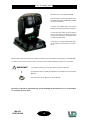
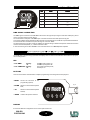
We thank you for choosing the MH-250.
Characterized by an attracting design and an
incredible optic system, the MH-250 is suitable
for any kind of ambient.
A modern and reliable electric circuit gives
stability and functioning safety for long time.
To make the most of this unit and to make it
work correctly in the years, before connecting
it to its source and using it, we suggest you to
carefully read this manual.
In this way you could be more familiar with
its commands and connections so to easily
use it.
All the sections of this manual have been studied to make as easy and complete as possible the use of the MH-250.
To make the manual more clear and easy to consult, we have used the following symbols and conventions:
very important warnings, to be read with the maximum attention;
important parts of the text that give details and/or explanations on the use of the
MH-250;
practical advices for an efficient use of the MH-250.
The safety of the unit is guaranteed only strictly following the instructions, so it is recommended
to accurately preserve them.
!
IMPORTANT
!

MH-250
CODE 991249
SAFETY PRECAUTIONSSAFETY PRECAUTIONS
SAFETY PRECAUTIONSSAFETY PRECAUTIONS
SAFETY PRECAUTIONS
3
•PROTECTION AGAINST FIRE
1) This unit has been made to work only with the Lamp: MSD 250/2 (PHILIPS).
! ABSOLUTELY NEVER USE OTHER KIND OF LAMPS.
2) Keep a minimum distance of 0,3 mt. from walls or any inflammable surface.
3) Keep a minimum distance of 1 mt. from lighted objects.
4) Replace the fuses with others of the same kind and value (MAIN FUE 5x20 250V 5A; ELEC FUSE 5x20 250V 2A).
5) Do not install the projector close to heat sources. Do not lay the connection cables on the projector when it is hot.
•PROTECTION AGAINST ELECTRIC SHOCKS
1) This projector must be earthed.
2) Class I equipment. The protection conductor must be part of the power supply cable.
3) For the connection to the main power supply proceed as in fig. 2, page 6.
4) Disconnect the power supply before the Lamp replacement or before opening the unit.
5) Do not install the projector outdoors, exposed to rain or moisture.
•PROTECTION AGAINST MECHANICAL HAZARDS
1) When installing the projector use a safety chain.
2) To avoid explosion risks, open the projector only after 5 minutes after the lamp is off.
3) The temperature of the projector can reach 85°C. Wait for almost 5 minutes before operating on it.
4) Replace the Lamp if it is damaged or deformed by the heat.
•PROTECTION AGAINST UV RADIATIONS HAZARDS
1) Do not start on the projector without the protecting screen or if the lenses and the ultra-violet filters are
damaged.
2) The protecting screens, the lenses and the ultra-violet filters must be replaced if visibly damaged and if their
efficiency has been reduced, for example by slits or deep cuts.
3) Do not directly look at the Lamp when it is on.
•WARNINGS
1) Do not dismantle and modify the unit.
2) To avoid any inflammable liquids, water or metal objects entering the unit.
READ ALL CAUTIONS AND WARNINGS PRIOR TO OPERATE THIS EQUIPMENT.
INSTRUCTIONS TO PREVENT INJURIES OR DAMAGES DUE TO FIRE, ELECTRIC SHOCKS, MECHANICAL
HAZARDS AND UV RADIATIONS HAZARDS.
IMPORTANT
!

MH-250
CODE 991249
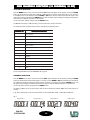
PMALPMAL PMAL PMALPMAL
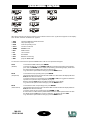
)SPILIHP(2/052DSMpmalegrahcsiD
K°005.8:erutarepmetruoloC
sruoh0002:efilpmalegarevA
TNEMEVOMTNEMEVOM TNEMEVOM TNEMEVOMTNEMEVOM
).ces6.1(TLIT°072,).ces7.2(NAP°045:noitulosertib61ro8rotomreppetS
.erutaefgninoitisoper-otuadnaredocnehtiwpooldesolc:lortnoC
dnalatnoziroheht,srotomreppetsehtfospets-orcimfometsysdetacitsihposaotsknahT
.stnemevomwolsdnatsafhtobnietaruccadnaraenilylemertxeeratsnemevomlacitrev
LATNOZIROHLATNOZIROH LATNOZIROH LATNOZIROHLATNOZIROH
TNEMEVOM
.ces7,2.nim:emitnoituloveR.NAP°045
.noitulosertib61
LACITREVLACITREV LACITREV LACITREVLACITREV
TNEMEVOM
.ces6,1.nim:emitnoituloveR.TLIT°072
.noitulosertib61
SRUOLOCSRUOLOC SRUOLOC SRUOLOCSRUOLOC ETIHW+SRUOLOCIB6+SRUOLOC51
.)tceffewobniar(sdeepsstnereffideerhttaetatornacleehwruolocehT
SOBOGSOBOG SOBOG SOBOGSOBOG ETIHW+)elbegnahcretnillaciorhcid2+cillatem7(SOBOGGNITATOR9
.)tceffewobniar(sdeepsstnereffideerhttaetatornacleehwobogehT
TUOKCALB/OBORTSTUOKCALB/OBORTS TUOKCALB/OBORTS TUOKCALB/OBORTSTUOKCALB/OBORTS
REMMID
ycneuqerfelbatsujdanahtiwtceffeOBORTS;tceffeTUOKCALB
.)ces/hsalf01.xam,ces/hsalf1.nim(
.ootREMMIDasadesuebnacRETTUHSehT
SUCOFSUCOF SUCOF SUCOFSUCOF -m1:dezirotoM
MSIRPGNITATORMSIRPGNITATOR MSIRPGNITATOR MSIRPGNITATORMSIRPGNITATOR .sdeepsstnereffidruof,MSIRPsecaf-ruofgnitatoR
TSORFTSORF TSORF TSORFTSORF muideM
REWOPTUPNIREWOPTUPNI REWOPTUPNI REWOPTUPNIREWOPTUPNI
.zH05;caV032:egatlovgnitarepolanimoN•
.W053:ylppusrewopdetaR•
.)caV032(A8.1:tnerruclanimoN•
GNIKROWGNIKROW GNIKROW GNIKROWGNIKROW
NOITISOP
.noitisopynA
SNOISNEMIDSNOISNEMID SNOISNEMID SNOISNEMIDSNOISNEMID
)HxDxW(
.5egap,1.gif;).xam045(064x063x004.mm
THGIEWTHGIEW THGIEW THGIEWTHGIEW 81.gK
YDOBYDOB YDOB YDOBYDOB .muinimuladnacitsalP
TECHNICAL FEATECHNICAL FEA
TECHNICAL FEATECHNICAL FEA
TECHNICAL FEATURESTURES
TURESTURES
TURES
∞
IMPORTANTE
!
4
SAFETY PRECAUTIONSSAFETY PRECAUTIONS
SAFETY PRECAUTIONSSAFETY PRECAUTIONS
SAFETY PRECAUTIONS
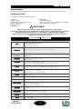
YOUR REFERENCE
Cite the model and the serial number anytime you contact your retailer to ask for information or assistance.
STANDARD PACKAGE
The standard package of the MH-250 contains:
1) Projector ON REQUEST:
2) Mains connector * Lamp (code 063567)
3) DMX XLR5 (pc. 2) signal connectors * Flight Case without wheels x 2 MH-250 (code 194985)
4) Screw bolts M8 (pc. 4) * Black clamp Ø50 (code 194019)
5) User’s manual
6) Guarantee
Make sure that the unit has not been damaged during the transportation.
In case it has happened or in case the unit does not work correctly, immediately contact the Retailer.
If the unit has been directly sent to you , immediately contact the Freight Company.
Only the final receiver (the person or the Company that receive the unit) is in the position to
complain for the above inconveniences.

MH-250
CODE 991249
400 mm
360 mm
54
0 m
m
46
0 m
m
TECHNICAL FEATECHNICAL FEA
TECHNICAL FEATECHNICAL FEA
TECHNICAL FEATURESTURES
TURESTURES
TURES
ASSEMBLINGASSEMBLING
ASSEMBLINGASSEMBLING
ASSEMBLING
5
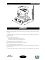
fig. 1
!Before installing the MH-250, make sure that the carrying structure is safe and able to support the weight of
the unit.
The MH-250 is equipped with 4 screw-cut holes to fix clamps and/or screw bolts M8 (already supplied in the
STANDARD PACKAGE).
!Once mounting ends, make sure that:
• the projector has been correctly and safely mounted;
• the projector movement is free from any kind of obstacles.
!Always make sure that you are using a safety chain.
!Do not install the unit outdoor directly exposed to rain or moisture.
!To avoid installing the projector close to heat sources.
!The unit must be at a minimum distance of 30 cm. from the walls or from any inflammable material and 1 mt.
from lighted objects.
!The unit must be placed where it could be easily aerated. To avoid obstructing the in/out air gratings.

MH-250
CODE 991249
MAIN IN
DMX IN
ON
OFF
DMX OUT
ON=DMX line
terminator
ON=DMX Gnd
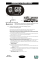
fig. 2
fig. 2/a
CONNECTION TCONNECTION T
CONNECTION TCONNECTION T
CONNECTION TO THE POWER SUPPLO THE POWER SUPPL
O THE POWER SUPPLO THE POWER SUPPL
O THE POWER SUPPLYY
YY
Y
6
BEFORE USING THE PROJECTOR
!Carefully read the precautions on page 3 before installing the projector.
In particular read the following points:
1) Disconnect the power supply before replacing the lamp or doing any maintenance job.
2) Do not open the projector if are not passed at least 5 minutes after it went off.
3) Always wear protective gloves and goggles to replace the lamp or to work inside the projector.
4) The protecting screens, the lenses and the ultra-violet filters must be replaced if visibly damaged.
Slits or deep cuts remarkably reduce their efficiency.
5) To avoid any bad performance of the projector or that the lamp breakage could damage its optic,
replace the lamp as soon as it reaches its average life time (2000 hrs).
6) Periodically clean the in/out air grates.
7) In case the projector must be held on a structure (truss), make sure that it is well and safely fixed,
even using a safety chain from the projector to the structure.
8) Do not install the projector outdoors, directly exposed to rain and moisture.
9) Before connecting the projector to the main power supply, make sure that the working voltage and
frequency correspond to the values indicated on the label (fig. 2/a).
The MH-250 is supplied to work at a working voltage of 230V 50Hz (60Hz on request); 1,8A.
For being supplied with a voltage of 100-120V it is absolutely necessary an auto-transformer with
the following characteristics:
• Output voltage 230V.
• Output current 4A.
10) The connection of the projector to the mains is described in fig. 2:
10 a) Do not install the projector close to heat sources. Do not lay the connection cables on the
projector when it is hot.
10 b) The unit must be placed where it could be easily aerated. To avoid obstructing the in/out air
gratings.
10 c) The projector must be distanced almost 0,3 mt. from walls or any inflammable surface
and almost 1mt. from lighted objects.
11) Temperature on the unit’s external surface:
• after 5 minutes Tc = 65°C.
• when the thermic balance has been reached Tc = 85°C.
The unit must be connected to the earth. The inobservance of these
instructions automatically makes the guarantee expiring.
IMPORTANT
!
POWER SUPPLY INPUT
L = PHASE (Brown)
N = NEUTRAL (Blue)
= EARTH (Green - Yellow)

MH-250
CODE 991249
L
A
M
P
S
A
D
J
U
T
L
A
M
P
A
D
J
U
S
T
L
A
M
P
A
D
J
U
S
T
O
P
E
N
LAMP MSD 250W GY9.5
O
P
E
N
D
I
S
C
O
N
N
E
CT PO
W
ER
A
ND
W
AIT
30
0
SE
C.
BE
FORE
O
P
E
N
I
N
G
C
A
U
T
ION! V
ER
Y
H
OT
L
A
MP
•
EX
P
LO
SI
ON HA
Z
A
R
D
L
A
M
P
S
A
D
J
U
T
L
A
M
P
A
D
J
U
S
T
L
A
M
P
A
D
J
U
S
T
O
P
E
N
LAMP MSD 250W GY9.5
O
P
E
N
D
I
S
C
O
N
N
E
CT PO
W
ER
A
ND
W
AIT
30
0
SE
C.
BE
FORE
O
P
E
N
I
N
G
C
A
U
T
ION! V
ER
Y
HOT
L
A
MP
•
EXP
LO
SI
ON HA
Z
A
R
D
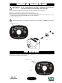
fig. 3/a
LAMP REGULATION PAWLS
fig. 4
To adjust the lamp, operate on the pawls placed on the lamp-holder cover (fig. 4). In this way it is possible to reach
the best light and uniformity of the light beam.
LAMP ROOM OPENING PAWLS
fig. 3
LAMP ADJUSTMENTLAMP ADJUSTMENT
LAMP ADJUSTMENTLAMP ADJUSTMENT
LAMP ADJUSTMENT
7
MOUNTING AND REPLAMOUNTING AND REPLA
MOUNTING AND REPLAMOUNTING AND REPLA
MOUNTING AND REPLACING THE LAMPCING THE LAMP
CING THE LAMPCING THE LAMP
CING THE LAMP
In case of replacement of the Lamp or maintenance, never open the
unit unless are passed at least 5 minutes after it went off.
IMPORTANT
!
1) Disconnect the projector before replacing the lamp. Wear protective gloves and goggles.
2) Unscrew the pawls placed on the rear side of the head (fig. 3).
3) Open the lamp-holder cover placed on the rear side of the head (fig. 3/a).
4) Put the lamp in the apposite lamp-holder (fig. 3/a). Avoid touching the lamp bulb with the nude hands; in case it
accidentally happens, clean the lamp bulb with a dry cloth and alcohol.
5) Close the lamp-holder cover.
To check the lamp average time efficiently, it is suggested to reset the counter (see LHrS function, page 10).

MH-250
CODE 991249
8
fig. A
D
M
X
IN
ON
OFF
D
M
X
O
U
T
O
N
=
D
M
X
lin
e
te
r
m
in
a
to
r
O
N
=
D
M
X
G
n
d
DMX LINE TERMINAL
Do not connect or wrongly connect the DMX line terminal is probably the most common cause of a defective
functioning of a DMX line.
The DMX line terminal is a resistance placed between the two data pin 2 and 3 at the end of the line.
The terminal resistance should ideally have the same value of the impedance of the DMX connecting cable.
On the MH-250 is inserted a resistance value of 100 Ohm that can be started by a switch placed on the base rear panel
(fig. A).
!It is suggested for all DMX systems to use a DMX line terminal (DMX line terminator ON, fig. A) only on the
last connected unit.
!Usually the DMX connection is insulated from the unit mass. In some cases (very rarely) it is suggested to act
in a different way. On the base rear panel there is a switch that connect electronical the two masses (DMX Gnd).
Use this switch (DMX Gnd ON, fig. A) only if the DMX line functioning is not stable although connection and
termination are correct.
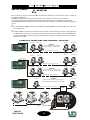
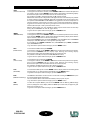
EXAMPLES OF CONNECTIONS: DMX CONTROLLER - PROJECTOR
DMX SIGNAL CONNECTIONDMX SIGNAL CONNECTION
DMX SIGNAL CONNECTIONDMX SIGNAL CONNECTION
DMX SIGNAL CONNECTION
IMPORTANT
!
DMX CONTROLLER
LINE TERMINAL
(fig. A)
PROJECTOR
LINE TERMINAL
(fig. A)
DMX CONTROLLER
LINE TERMINAL
(fig. A)
LINE TERMINAL
(fig. A)
DMX CONTROLLER
PROJECTOR
PROJECTOR PROJECTOR
PROJECTOR PROJECTOR
LAST PROJECTOR
LINE < 100mt. (with microphonic or audio cable)
LINE < 100mt. (with microphonic or audio cable)
LAST PROJECTOR
LAST PROJECTOR
LAST PROJECTOR
SIGNAL
AMPLIFIER
DMX 1 output line
DMX 2 output line
EXAMPLE 1
Controller-projector connection with
only one DMX 512 OUTPUT LINE
EXAMPLE 2
Controller-projector connection with
two or more DMX 512 OUTPUT LINE
EXAMPLE 3
Controller-projector connection with only one
DMX 512 OUTPUT LINE long more than 150mt.
LINE > 150mt. (with microphonic or data transmission cable)
LINE < 100mt. (with microphonic or audio cable)
PROJECTOR
PROJECTOR
PROJECTOR
PROJECTOR

MH-250
CODE 991249
CONFIGURACONFIGURA
CONFIGURACONFIGURA
CONFIGURATION AND CONTROLSTION AND CONTROLS
TION AND CONTROLSTION AND CONTROLS
TION AND CONTROLS
fig. 5/a
fig. 6
fig. 5
NIPNIP NIP NIPNIP ERIWERIW ERIW ERIWERIW LANGISLANGIS LANGIS LANGISLANGIS
1DLEIHSVO/NRUTER/DNUORG
2ROTCUDNOCRENNI)DETREVNI,-(TNEMELPMOCATAD
3ROTCUDNOCRENNI)DETREVNINON,+(EURTATAD
4.C.N
5.C.N
9
DMX SIGNAL CONNECTIONDMX SIGNAL CONNECTION
DMX SIGNAL CONNECTIONDMX SIGNAL CONNECTION
DMX SIGNAL CONNECTION
LAMP OFF
DMX
DMX IN
ON
OFF
DMX OUT
ON=DMX line
terminator
ON=DMX Gnd
DMX SIGNAL CONNECTION
The DMX signal connection to the MH-250 must be done through the input signal connectors XLR 5 pins, placed
on the rear panel of the projector (fig. 5).
The nomenclature of the pins of the DMX input connectors is listed in the table reported in fig. 5/a.
To avoid any problem in the transmission of the signal it is recommended to use a cable for very fast data transmissions.
A normal audio cable is suitable only for lines long not more than 100mt.
The best performances and the maximum stability are obtained using a shielded microphonic cable which section
must be of at least 2x0,25mm, or, a data transmission cable.
In case of lines long more than 150/200mt. it is recommended to use a DMX Repeater Amplifier.
On the MH-250 control panel (fig. 6) besides the display there are some led and buttons which allow the projector
correct configuration.
LED
• Led “DMX” flashing: the DMX input signal is On;
off: the DMX input signal is Off..
• Led “LAMP OFF” flashing: the control board lamp is Off;
off: the lamp is On.
BUTTONS
There are four buttons which allow the complete programming and management of the projector:
• MENU allows the selection of the
programming options;
• DOWN allows to run the selected options
back;
• UP allows to run the selected options
forward;
• ENTER confirms the options selected.
DISPLAY
It shows the different configuration menu and the options selected.

MH-250
CODE 991249
After 20 seconds the unit has been turned on, the software number in the “X_00” format appears on the display.
Yhen the first of thirteen available menu appears:
• Addr allows the DMX-512 address allocation
• LHrS lamp operating hours
• FHrS total unit operating hours
• nChn number of channels
• dMMd DIMMER mode
• IPan PAN inversion
• ItLt TILT inversion
• teSt AUTOTEST
• FLIP DISPLAY overturning
• rSEt projector RESETTING
To select one of the functions press the MENU button until the one requested will appear.
Addr
LHrS
FHrS
nChn
IPan
ItLt
teSt
FLIP
rSEt
dMMd
10
PROGRAMMING FUNCTIONSPROGRAMMING FUNCTIONS
PROGRAMMING FUNCTIONSPROGRAMMING FUNCTIONS
PROGRAMMING FUNCTIONS
LHrS
(Lamp Hours)
Addr
(Address)
FHrS
(Fixture Hours)
To visualize the DMX address press ENTER.
To change the address, use the DOWN or UP button and when the preferred one appears,
press and hold ENTER until the display stops flashing (the flashing display shows that
the option selected is different from the one already set).
To go back to the options without changes, press the MENU button.
To visualize the total unit operating hours press ENTER.
The highest number of hours to be reckoned is 3000. Over this number the display will show
Gr3t (Greater than 3 thousands).
To set the counter to zero contemporaly press DOWN and UP.
A check of the no volatile memory will be effected and the dafault options will be set. Now
the display will show Init. If the memory is defective, the display will show FAIL.
To go back to the options without changes, press the MENU button.
To visualize the lamp operating hours press ENTER.
The highest number of hours to be reckoned is 3000. Over this number the display will show
Gr3t (Greater than 3 thousands).
To set the counter to zero contemporaly press DOWN and UP (it is suggested to effect this
operation every time the lamp is replaced, ref. page 7).
Now the message CLLH (CLear Lamp Hours) will appear on the display.
To go back to the options without changes, press the MENU button.

MH-250
CODE 991249
11
dMMd
(DIMMER Mode)
nChn
(number of Channel)
To visualize the DIMMER mode press ENTER.
To change the mode press the DOWN or UP button and, when the preferred one is reached,
press and hold ENTER until the display stops flashing (the flashing display shows that the
option selected is different from the one already set).
It changes the DIMMER answer so that the DIMMER is close with DMX 0 value and DIMMER
wholly open with DMX 255 value or the opposite operating mode.
It is possible to set: CLOSE (0 DIMMER close, 255 DIMMER open), OPEn (0 DIMMER
open, 255 DIMMER close).
To go back to the options without changes, press the MENU button.
IPan
(PAN Inversion)
ItLt
(TILT Inversion)
teSt
(AUTOTEST)
FLIP
(DISPLAY overturning)
rSEt
(RESET)
PROGRAMMING FUNCTIONSPROGRAMMING FUNCTIONS
PROGRAMMING FUNCTIONSPROGRAMMING FUNCTIONS
PROGRAMMING FUNCTIONS
To visualize the number of channels press ENTER.
To change the number of the channels, use the DOWN or UP button and when the preferred
one appears, press and hold ENTER until the display stops flashing (the flashing display
shows that the option selected is different from the one already set).
It is possible to set 10 or 11 channels (8 bit) or 13 channels (16 bit).
With the last channel (in the configuration of the projector with 11/13 channels), it is possible
to set the auxiliary functions of MH-250. Especially it is possible to set the ramp speed. The
two options are SLOW RAMP or FAST RAMP. It is suggested to use the low ramp when an
extreme uniformity of movement is necessary (in live or television applications), while it is
suggested to use the fast ramp when a great speed of movement is the most important
element (discotheques or with a particular kind of music).
With the AUX function it is even possible to effect projector board reset and the lamp
turning off (see APPENDIX “A” and “B”, pages 34-37).
To go back to the options without changes, press the MENU button.
To effect the complete RESET press and hold ENTER until the flashing r-on message
(reset on) will appear on the display. When the RESET procedure ends, the projector goes
back to the normal lay-out.
To go back to the options without changes, press the MENU button.
The DISPLAY visualization can be normal or overturned. Pressing the ENTER button, the
two methods will appear alternatively.
The one selected will be memorized immediately in the projector lay-out.
To go back to the options without changes, press the MENU button.
To set the AUTOTEST press and hold ENTER until the display will show the flashing t-on
message (test on). To disconnect the AUTOTEST press the MENU button.
To go back to the options without changes, press the MENU button.
To visualize the TILT method press ENTER.
To change the method, use the DOWN or UP button and when the preferred one appears,
press and hold ENTER until the display stops flashing (the flashing display
shows that the option selected is different from the one already set).
It is possible to set: no (normal) normal TILT, tI (TILT Inversion).
To go back to the options without changes, press the MENU button.
To visualize the PAN method press ENTER.
To change the method, use the DOWN or UP button and when the preferred one appears,
press and hold ENTER until the display stops flashing (the flashing display
shows that the option selected is different from the one already set).
It is possible to set: no (normal) normal PAN, PI (PAN Inversion).
To go back to the options without changes, press the MENU button.

MH-250
CODE 991249
For the PAN-TILT movement, it is possible to select a small configuration (8 BIT) using 10/11 DMX channels or a big
configuration (16 BIT) using 13 DMX channels. Selecting the option 11/13 channels it is also possible to reset the
motors and turn the lamp Off through the controller.
8 BIT MODE SELECTION
Press the MENU button on the control panel until the nChn option will appear on the display: pressing the ENTER
button, the mode already set will appear (10, 11 or 13 channels). For 8 BIT mode, it is necessary to set 10 or 11
channels on the display (activating or not the RESET option and the lamp turning off through the controller). Press
the DOWN or UP button until the preferred number will appear. Then memorize it pressing and holding the
ENTER button, until the display stops flashing (the flashing shows that the option selected is different from the
one already set).
To leave the option without changes press the MENU button.
The MH-250, selected for 8 BIT operating, needs 10/11 channels to check its functions.
The relation between channels and functions is described in the following table:
For the complete DMX values see APPENDIX “A”, page 34.
ADDRESS SELECTION
Press the MENU button on the control panel until the Addr option will appear on the display: pressing the ENTER
button, the predetermined channel will appear. To change it use the DOWN or UP button following the example of
fig. 7. When the preferred channel has been reached, memorize it pressing and holding the ENTER button, until
the display stops flashing (the flashing shows that the option selected is different from the one already set).
To leave the option without changes press the MENU button.
The flashing “DMX” led on the panel shows that the data transmission between DMX control and projector is
working.
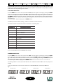
In fig. 7 are indicated the correct channels numbers to use four MH-250 (8 BIT, 10 channels) in DMX 512.
fig. 7
DMX CHANNELS FUNCTIONS (10/11 CHANNELS, 8 BIT)DMX CHANNELS FUNCTIONS (10/11 CHANNELS, 8 BIT)
DMX CHANNELS FUNCTIONS (10/11 CHANNELS, 8 BIT)DMX CHANNELS FUNCTIONS (10/11 CHANNELS, 8 BIT)
DMX CHANNELS FUNCTIONS (10/11 CHANNELS, 8 BIT)
.oNLENNAHC.oNLENNAHC .oNLENNAHC .oNLENNAHC.oNLENNAHC NOITCNUFROTCEJORPNOITCNUFROTCEJORP NOITCNUFROTCEJORP NOITCNUFROTCEJORPNOITCNUFROTCEJORP
1SOBOG.TOR
2WOBNIAR+SRUOLOC
3WOBNIAR+SOBOG
4DEEPSEBORTS/RETTUHS
5ESRAOCNAP
6ESRAOCTLIT
7REMMID
8DEEPSSROTOM
9SUCOF
01MSIRP.TOR/MSIRP/TSORF
11XUA
12
Projector No. 1 Projector No. 2 Projector No. 3 Projector No. 4
Channels 1-10 Channels 11-20 Channels 21-30 Channels 31-40

MH-250
CODE 991249
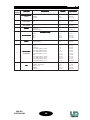
16 BIT MODE SELECTION
Press the MENU button on the control panel until the nChn option will appear on the display: pressing the ENTER
button, the mode already set will appear (10, 11 or 13 channels). For a better 16 BIT performance , it is necessary
to set 13 channels on the display. Press the DOWN or UP button until the preferred number will appear. Then
memorize it pressing and holding the ENTER button, untill the display stops flashing (the flashing shows that the
option selected is different from the one already set).
To leave the option without changes press the MENU button.
The MH-250, selected for 16 BIT operating, needs 13 channels to check its functions.
The relation between channels and functions is described in the following table:
For the complete DMX values see APPENDIX “B”, page 36.
ADDRESS SELECTION
Press the MENU button on the control panel until the Addr option will appear on the display: pressing the ENTER
button, the predetermined channel will appear. To change it use the DOWN or UP button following the example of
fig. 8. When the preferred channel has been reached, memorize it pressing and holding the ENTER button, until
the display stops flashing (the flashing shows that the option selected is different from the one already set).
To leave the option without changes press the MENU button.
The flashing “DMX” led on the panel shows that the data transmission between DMX control and projector is
working.
In fig. 8 are indicated the correct channels numbers to use four MH-250 (16 BIT, 13 channels) in DMX 512.
fig. 8
DMX CHANNELS FUNCTIONS (13 CHANNELS, 16 BIT)DMX CHANNELS FUNCTIONS (13 CHANNELS, 16 BIT)
DMX CHANNELS FUNCTIONS (13 CHANNELS, 16 BIT)DMX CHANNELS FUNCTIONS (13 CHANNELS, 16 BIT)
DMX CHANNELS FUNCTIONS (13 CHANNELS, 16 BIT)
.oNLENNAHC.oNLENNAHC .oNLENNAHC .oNLENNAHC.oNLENNAHC NOITCNUFROTCEJORPNOITCNUFROTCEJORP NOITCNUFROTCEJORP NOITCNUFROTCEJORPNOITCNUFROTCEJORP
1SOBOG.TOR
2WOBNIAR+SRUOLOC
3WOBNIAR+SOBOG
4DEEPSEBORTS/RETTUHS
5ESRAOCNAP
6ENIFNAP
7ESRAOCTLIT
8ENIFTLIT
9REMMID
01DEEPSSROTOM
11SUCOF
21MSIRP.TOR/MSIRP/TSORF
31XUA
13
Projector No. 1 Projector No. 2 Projector No. 3 Projector No. 4
Channels 1-13 Channels 14-26 Channels 27-39 Channels 40-52

MH-250
CODE 991249
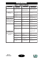
TABLE 1 - GENERAL PROBLEMS
TROUBLESHOOTINGTROUBLESHOOTING
TROUBLESHOOTINGTROUBLESHOOTING
TROUBLESHOOTING
SMELBORPSMELBORP SMELBORP SMELBORPSMELBORP ELBABORPELBABORP ELBABORP ELBABORPELBABORP
SNOSAER
SLORTNOCSLORTNOC SLORTNOC SLORTNOCSLORTNOC DETSEGGUSDETSEGGUS DETSEGGUS DETSEGGUSDETSEGGUS
SNOITULOS
seodrotcejorpehTseodrotcejorpehT seodrotcejorpehT seodrotcejorpehTseodrotcejorpehT
.tratston
siylppusrewopehT
.gnissim
rewopehterusaeM
ehtnonoisnetylppus
.rotcennoclapicnirp
rotcejorpehtylppuS
.rewopthgirehthtiw
ylppusrewopevitcefeD
ro/dnaselbac
.srotcennoc
dnaselbackcehC
.sutatssrotcennoc
ro/dnaselbacecalpeR
.srotcennoc
siesuflarenegehT
.detpurretni
.sutatsesufehtkcehCfi(esufehtecalpeR
.)evitcefed
eht,krowsnafehTeht,krowsnafehT eht,krowsnafehT eht,krowsnafehTeht,krowsnafehT
eht(ffosiyalpsid
tesertonseodtinu
gnihctiwsretfaflesti
.)ffosipmalehtdna
.enilV5+ehtnotrohS.enilV5+ehtkcehCevitcefedecalpeR
.enilV5+ehtfostrap
.detpurretni7DedoiD7DedoidehtkcehC
.sutats
fi(7DedoidecalpeR
.)evitcefed
tonronoitcetorpni5U
.gnikrow
.sutats5UehtkcehCfi(5UehtecalpeR
.)evitcefed
skrowrotcejorpehTskrowrotcejorpehT skrowrotcejorpehT skrowrotcejorpehTskrowrotcejorpehT
ehttubyltcerroc
nruttonseodpmal
yltnettimretnirono
.ffosnrut
.pmalevitcefeDpmalehtkcehC
.sutats
.pmalehtecalpeR
ottohootsipmalehT
.nonrut
-pmalehtroftiaW
.gnilooc
erutarepmetmooR
.C°54nahtrehgih
-moorehtgnirB
ehtnihtiwerutarepmet
lamronehtfotimil
xam(gninoitcnuf
.).C°04
rewopwolooT
.deilppus
rewopehterusaeM
.deilppus
rewopehtkcehC
.ecruos
.retingievitcefeDretingiehtkcehC
.sutats
.retingiehtecalpeR
tsallabgnorW
.snoitcennoc
tsallabehtkcehC
.snoitcennoc
tsallabehttcennoC
.yltcerroc
erutarepmetedisniehT
.hgihootsi
cimrehtehttahtkcehC
sirotcejorpehtno
.nepo
fogniloocehtroftiaW
.moor-pmaleht
14

MH-250
CODE 991249
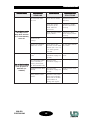
SMELBORPSMELBORP SMELBORP SMELBORPSMELBORP ELBABORPELBABORP ELBABORP ELBABORPELBABORP
SNOSAER
SLORTNOCSLORTNOC SLORTNOC SLORTNOCSLORTNOC DETSEGGUSDETSEGGUS DETSEGGUS DETSEGGUSDETSEGGUS
SNOITULOS
skrowrotcejorpehTskrowrotcejorpehT skrowrotcejorpehT skrowrotcejorpehTskrowrotcejorpehT
ehttubyltcerroc
nruttonseodpmal
yltnettimretnirono
.ffosnrut
seodnafdaehehT
.krowton
.sutatsnafehtkcehCfi(nafehtecalpeR
.)evitcefed
tcerrocehtkcehC
ehtfonoitcennoc
ROTOM-DAEH
.srotcennoc
-DAEHehttcennoC
srotcennocROTOM
.yltcerroc
rewopsnafehtkcehC
.selbacylppus
snafehttcennoC
selbacylppusrewop
..yltcerroc
riadetcurtsbO
.sgnitarg
-.sgnitargriaehtnaelC
ETOMERehtetavitcA
.lortnocFFOPMAL
ehtnotahtkcehC
XMDtsalehtrellortnoc
)31ro21.oN(lennahc
retaergeulavnosi
.052naht
lennahcXMDehtteS
.eulav0no
snoitcnufehtfoenOsnoitcnufehtfoenO snoitcnufehtfoenO snoitcnufehtfoenOsnoitcnufehtfoenO
sirotcejorpehtfo
.e.i(evitcefed
.)SOBOG
reppetsdegamaD
.rotom
stsetehttceffE
81egaptadebircsed
.)b3.fer(
reppetsehtecalpeR
.rotom
elbacgnitcennocehT
cprellortnocehtfo
detpurretnisidraob
.)BCPAM052TOM.fer(
stsetehttceffE
.71egaptadebircsed
-
revirdrotomdegamaD
.)9126L(
stsetehttceffE
81egaptadebircsed
.)a3.fer(
revirdrotomecalpeR
.)9126L(
leehwOBOGgnorW
.noitator
rewopehttcennocsiD
yllaunamdnaylppus
OBOGehttahtkcehc
sinoitatorleehw
.ralugerdnagniwolf
-
TROUBLESHOOTINGTROUBLESHOOTING
TROUBLESHOOTINGTROUBLESHOOTING
TROUBLESHOOTING
15

MH-250
CODE 991249
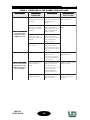
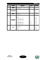
TABLE 2 - PROBLEMS TO THE CONNECTION DATA LINK
16
TROUBLESHOOTINGTROUBLESHOOTING
TROUBLESHOOTINGTROUBLESHOOTING
TROUBLESHOOTING
SMELBORPSMELBORP SMELBORP SMELBORPSMELBORP ELBABORPELBABORP ELBABORP ELBABORPELBABORP
SNOSAER
SLORTNOCSLORTNOC SLORTNOC SLORTNOCSLORTNOC DETSEGGUSDETSEGGUS DETSEGGUS DETSEGGUSDETSEGGUS
SNOITULOS
052-HMehtfoenoN052-HMehtfoenoN 052-HMehtfoenoN 052-HMehtfoenoN052-HMehtfoenoN
ehtotdnopser
.tupnirellortnoc
.ffosidelXMD
rellortnocXMD
ehtmorfdetcennocsid
.srotcejorp
ehtfikcehC
tsrifehtfonoitcennoc
si052-HMehtfo
.tcerroc
ehtylreporptcennoC
.rellortnocXMD
noitcennocdetpurretnI
XMDehtmorfelbac
tsrifehtotrellortnoc
.052-HM
detsetydaerlanaesU
tcennocdnaelbac
,emitreprotcejorpeno
detpurretniehtlitnu
.dnuofsielbac
XMDehtecalpeR
.elbac
ehtfo3dna2niP
ehtforotcennoc
eraelbacgnitcennoc
.detrevni
detsetydaerlanaesU
tcennocdnaelbac
,emitreprotcejorpeno
evitcefedehtlitnu
.dnuofsielbac
nielbacgnitcennoC
.tiucrictrohs
detsetydaerlanaesU
tcennocdnaelbac
,emitreprotcejorpeno
trohsnielbacehtlitnu
.dnuofsi
-HMeromroenO-HMeromroenO -HMeromroenO -HMeromroenO-HMeromroenO
etucexetonod052
ehtfostupnieht
rorellortnocXMD
.ylgnorwtiod
.sserddaXMDgnorWXMDehtfikcehC
ehtfosserdda
dnopserrocrotcejorp
folennahcXMDehtot
.rellortnoceht
ehtylreporperugifnoC
.sserddaXMD
asahrotcejorpenO
cpXMDevitcefed
.draob
detsetydaerlanaesU
tuoekatdnaelbac
enoenilehtmorf
litnu,emitreprotcejorp
ehthtiwenoeht
cpXMDevitcefed
.tuodnuofsidraob
evitcefedehtecalpeR
.draobcpXMD
tonsahenilXMDehT
.rotanimretXMDa
tsalehtnofikcehC
asierehtrotcejorp
.rotanimretXMD
rotanimretXMDatuP
rotcejorptsalehtno
.)8egap(

MH-250
CODE 991249
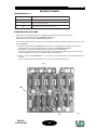
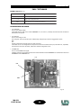
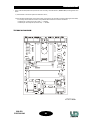
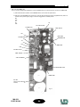
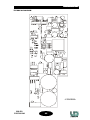
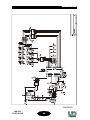
BOARD MOT250 (fig. 9)
PROBLEMS AND SOLUTIONS
• All the three led indicate that there are voltages and signals coming from the base circuits:
+30V and +5V come from the board POWER250 (pages 23-27);
DMX comes from the panel board DMX250 (pages 29-30).
To locate the trouble if one of the voltages is not present (for example led +5V off) check that it is off even on the
board POWER250:
+ 30V
+ 5V
DMX
fig. 9
MOTORS PC BOARD
SNOITCNUFDELSNOITCNUFDEL SNOITCNUFDEL SNOITCNUFDELSNOITCNUFDEL NOITPIRCSEDNOITPIRCSED NOITPIRCSED NOITPIRCSEDNOITPIRCSED
V03+detcetedylppusrewop
V5+detcetedylppusrewopcigol
XMDdetcetedlenapXMDehtmorflangislaires
17
2) if the led on the board POWER250 is on, it is necessary to carefully check all connections between the
differnt
boards. Probably a cable is interrupted or one connector is not inserted correctly.
1) if the led is off on the board POWER250, disconnect the circuit MOT250 disconnecting the connector.
If the led still is off, go on with the instructions on page 23 - “POWER SUPPLY BOARD”.
If the led starts, the trouble (probable a short) is located on the circuit MOT250.
In that case, make sure that there is an overheating component. Where possible take it out from the base
and give voltage to the circuit. If the led starts, replace the component.
TROUBLESHOOTINGTROUBLESHOOTING
TROUBLESHOOTINGTROUBLESHOOTING
TROUBLESHOOTING

MH-250
CODE 991249
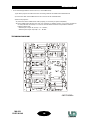
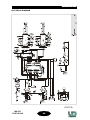
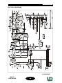
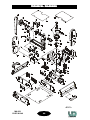
•MOT250MA•
TECHNICAL DIAGRAM
18
TROUBLESHOOTINGTROUBLESHOOTING
TROUBLESHOOTINGTROUBLESHOOTING
TROUBLESHOOTING
• If one of the Stepper Motors does not move (i.e. the GOBO wheel):
1) put off the projector and disconnect the connecting cables of the GOBO and COLOUR wheels.
2) connect the cable of the GOBO wheel to the connector of the COLOUR wheel.
3) start on the projector:
3a) if the motor of the GOBO wheel works properly, it is necessary to replace U5 (L6219).
3b) if the GOBO motor still does not work, it is necessary to carefully check it, so as all the connections
circuits (cable and connectors). For a correct check of cables and motors it is possible to effect the
following resistor test:
• between pin 1 and pin 21 (on U5) r =6 ÷ 18 Ohm;
• between pin 2 and pin 5 (on U5) r =6 ÷ 18 Ohm.

MH-250
CODE 991249
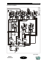
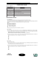
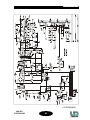
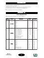
•MOT250S•
ELECTRICAL DIAGRAM
19
TROUBLESHOOTINGTROUBLESHOOTING
TROUBLESHOOTINGTROUBLESHOOTING
TROUBLESHOOTING
Page is loading ...
Page is loading ...
Page is loading ...
Page is loading ...
Page is loading ...
Page is loading ...
Page is loading ...
Page is loading ...
Page is loading ...
Page is loading ...
Page is loading ...
Page is loading ...
Page is loading ...
Page is loading ...
Page is loading ...
Page is loading ...
Page is loading ...
Page is loading ...
Page is loading ...
Page is loading ...
-
 1
1
-
 2
2
-
 3
3
-
 4
4
-
 5
5
-
 6
6
-
 7
7
-
 8
8
-
 9
9
-
 10
10
-
 11
11
-
 12
12
-
 13
13
-
 14
14
-
 15
15
-
 16
16
-
 17
17
-
 18
18
-
 19
19
-
 20
20
-
 21
21
-
 22
22
-
 23
23
-
 24
24
-
 25
25
-
 26
26
-
 27
27
-
 28
28
-
 29
29
-
 30
30
-
 31
31
-
 32
32
-
 33
33
-
 34
34
-
 35
35
-
 36
36
-
 37
37
-
 38
38
-
 39
39
-
 40
40


LED Lighting Moving Head MH-250 User manual
- Category
- Stroboscopes & disco lights
- Type
- User manual
Ask a question and I''ll find the answer in the document
Finding information in a document is now easier with AI
Other documents
-
Coemar iSpot 1200 MB User manual
-
-
Clay Paky ALPHA BEAM 700 User manual
-
-
SGM Victory II User manual
-
-
-
-
ProLights RUBYFCX User manual
-