Paxar Mobile Printing Station Monarch 9476 User manual
- Category
- Label printers
- Type
- User manual
This manual is also suitable for

TC9476OI Rev. AA 4/99 ©1995 Monarch Marking Systems, Inc. All rights reserved.
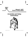
Assembly and Setup
Instructions
Monarch
TM
9476
TM
Mobile Printing Station

Each product and program carries a respective written warranty, the only warranty on
which the customer can rely. Monarch reserves the right to make changes in the
product, the programs, and their availability at any time and without notice. Although
Monarch has made every effort to provide complete and accurate information in this
manual, Monarch shall not be liable for any omissions or inaccuracies. Any update
will be incorporated in a later edition of this manual.
©1995 Monarch Marking Systems, Inc. All rights reserved. No part of this
publication may be reproduced, transmitted, stored in a retrieval system, or
translated into any language in any form by any means, without the written
permission of Monarch Marking Systems, Inc.
WARNING
This equipment has been tested and found to comply with the limits for a Class A digital
device, pursuant to Part 15 of the FCC Rules. These limits are designed to provide
reasonable protection against harmful interference when the equipment is operated in
a commercial environment. This equipment generates, uses, and can radiate radio
frequency energy and, if not installed and used in accordance with the instruction
manual, may cause harmful interference to radio communications. Operation of this
equipment in a residential area is likely to cause harmful interference in which case the
user will be required to correct the interference at his own expense.
CANADIAN D.O.C. WARNING
This digital apparatus does not exceed the Class A limits for radio noise emissions from
digital apparatus set out in the Radio Interference Regulations of the Canadian
Department of Communications.
Le présent appareil numérique n’émet pas de bruits radioélectriques dépassant les
limites applicables aux appareils numériques de la classe A prescrites dans le
Réglement sur le brouillage radioélectrique édicte par le ministère des Communications
du Canada.
9476 and 9490 are trademarks and Monarch is a registered trademark of Monarch Marking Systems, Inc.
Paxar is a trademark of Paxar Corporation.
Monarch Marking Systems
P.O. Box 608
Dayton, Ohio 45401

Preface
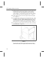
The Monarch 9476 Mobile Printing Station, or "the Station,"
allows you to mobilize and use up to four Monarch
®
9490
printers. The 12-volt battery stored in the Station powers the
printers. A portable data collection device or portable PC
sends the data to the printers through a single, shared
communication cable.
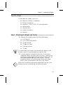
This document describes how to
F assemble the Station
F install the printers
F load fan-fold supplies
F charge the Station’s battery.
Audience ------------------------------------------------------------------------------------------------------
This manual is designed for the person assembling the Station
and setting it up to print supplies.
w
Only qualified service personnel may install or replace the
12-volt battery for the Station.
Service personnel should have appropriate technical training
and experience necessary to:
F install or replace a 12-volt battery
F be aware of hazards to which they are exposed in
installing or replacing the battery, and of measures to
minimize the danger to themselves or other persons.
i

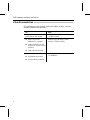
Other Documentation ------------------------------------------------------------------------------
To send data to the printers and print labels or tags, see the
following additional manuals:
To: See:
create online packets to
send data to the printer
MPCLII Packet Reference Manual
(TCMPCL2PM)
F define an online
address for a printer
Addressing a Monarch 9490
Printer (TCMPCLIDAD)
F select a printer on the
Station to receive online
packets
F select printer voltage
F load ribbon
9490 Operator’s Handbook
(TC9490OH)
F troubleshoot printers
F solve printer problems
9476 Assembly and Setup Instructions
ii

Table of Contents
Chapter 1. Assembling the Station . . . . . . . . . . . . . . . . . . . . . . 1-1
Parts List. . . . . . . . . . . . . . . . . . . . . . . . . . . . . . . . . . . . . . . 1-1
Tools You Need. . . . . . . . . . . . . . . . . . . . . . . . . . . . . . . . . . 1-3
Step 1: Attaching the Wheels and Casters . . . . . . . . . . . . 1-3
Step 2: Adjusting the Station’s Height . . . . . . . . . . . . . . . . 1-6
Step 3: Attaching the Cabinet Handle and Cord Bracket. . 1-7
Step 4: Attaching Optional Items . . . . . . . . . . . . . . . . . . . . 1-8
Attach the Push Handle . . . . . . . . . . . . . . . . . . . . . 1-9
Attach the Drop Shelf . . . . . . . . . . . . . . . . . . . . . . 1-10
Attach the Data Entry Terminal Cradle . . . . . . . . . 1-13
Step 5: Installing the Battery and Charger. . . . . . . . . . . . 1-14
Install the Battery . . . . . . . . . . . . . . . . . . . . . . . . . 1-14
Install the Battery Charger . . . . . . . . . . . . . . . . . . 1-18
Step 6: Installing the Printers. . . . . . . . . . . . . . . . . . . . . . 1-22
Attach the Printer Brackets . . . . . . . . . . . . . . . . . . 1-22
Attach the Printers. . . . . . . . . . . . . . . . . . . . . . . . . 1-23
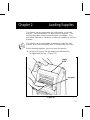
Chapter 2. Loading Supplies . . . . . . . . . . . . . . . . . . . . . . . . . . . 2-1
Loading Fan-Fold Supplies . . . . . . . . . . . . . . . . . . . . . . . . . 2-3
Loading Roll Supplies in Fan-Fold Printers. . . . . . . . . . . . . 2-9
Loading Ribbon. . . . . . . . . . . . . . . . . . . . . . . . . . . . . . . . . 2-14
Reloading a Ribbon Cassette . . . . . . . . . . . . . . . . . . . . . . 2-15
Printing . . . . . . . . . . . . . . . . . . . . . . . . . . . . . . . . . . . . . . . 2-17
Chapter 3. Charging the Battery. . . . . . . . . . . . . . . . . . . . . . . . . 3-1
Important Charging Information . . . . . . . . . . . . . . . . . . . . . 3-2
Battery Life . . . . . . . . . . . . . . . . . . . . . . . . . . . . . . . . . . . . . 3-3
iii

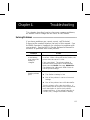
Chapter 4. Troubleshooting . . . . . . . . . . . . . . . . . . . . . . . . . . . . 4-1
Solving Problems . . . . . . . . . . . . . . . . . . . . . . . . . . . . . . . . 4-1
Changing Fuses . . . . . . . . . . . . . . . . . . . . . . . . . . . . . . . . . 4-2
Changing the Battery Fuse . . . . . . . . . . . . . . . . . . . 4-2
Changing the AC Fuse . . . . . . . . . . . . . . . . . . . . . . 4-4
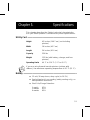
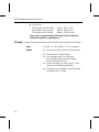
Chapter 5. Specifications . . . . . . . . . . . . . . . . . . . . . . . . . . . . . . 5-1
Utility Cart . . . . . . . . . . . . . . . . . . . . . . . . . . . . . . . . . . . . . 5-1
Battery . . . . . . . . . . . . . . . . . . . . . . . . . . . . . . . . . . . . . . . . 5-1
Charger . . . . . . . . . . . . . . . . . . . . . . . . . . . . . . . . . . . . . . . 5-3
9476 Assembly and Setup Instructions
iv

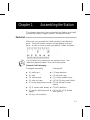
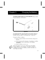
Chapter 1. Assembling the Station
This chapter describes how to assemble the Station and install
the battery, battery charger, printers, and optional items.
Parts List ----------------------------------------------------------------------------------------------------
Make sure you received the listed quantity of the following
parts. Check all internal cartons and packaging for these
parts. A ruler is shown to help you identify screws and bolts.
nThis list does not include parts for optional items. See
"Attaching Optional Items" for a list of these parts.
General Cart Packaging
Packaged separately: Package #1:
F (1) utility cart F (2) large washers
F (1) axle F (2) axle end caps
F (2) axle mounts F (1) chrome handle insert
F (2) axle end caps F (4) 1/4"-20 wing nuts (black)
F (1) heavy duty power cord F (2) 5/8" phillips screws
(black)
F (2) 4" casters with brakes F (2) M3.5 washers
F (1) plastic cable-tube and
clamp
F (4) 1/4"-20 x 3/4" slotted
bolts (black)
F (2) keys (in envelope)
1-1

Package #2: Inside Cart:
F (2) 8-32 nuts/
lockwashers (black)
F (1) green wire (inside cart)
F (2) 8-32 x 1/2" slotted
screws (black)
F (1) host input cable (encased
in cable tube)
F (1) cord bracket F (1) battery harness cable
Package #3
F (2) 8" wheels
Battery and Charger Packaging:
F (4) retainer rods F (1) battery charger
F (2-8) supply holder
brackets with magnets
F (2) universal battery
hold-down rubber brackets
F (1) power cord (packaged
in charger carton)
Package #1
F (1) rechargeable 12-volt
battery
F (2) M5 x 15mm phillips/hex
bolts
F (3 ) M5 lock washers
Package #2
F (4) 1/4"-20 wing nuts F (4) 1/4"-20 lock washers
F (2) M5 washers F (4) 1/4"-20 washers
F (2) M5 nuts F (1) M5 x 10mm phillips screw
9476 Assembly and Setup Instructions
1-2

Tools You Need--------------------------------------------------------------------------------------------
To assemble the Station, you need:
F flathead (common) screwdriver
F Phillips screwdriver
F wrenches: 7/16", 11/32", 1/4" and adjustable
F rubber mallet
F slip-joint pliers
F needle-nose pliers
F hammer
Step 1: Attaching the Wheels and Casters --------------------------------------------
1. Remove the following items from their packaging:
F (2) 8" wheels
F (2) 4" casters with brakes
F (2) axle mounts
F (2) axle end caps
F (2) large washers
F (1) axle
w
To avoid hitting your fingers, use needle-nose pliers to hold
the end cap as you are hammering it onto the axle.
2. You may need an assistant for this step. Remove the
collapsed Station assembly from the carton. Hold the top
piece of packaging against the top of the Station and turn
the Station upside down on a firm surface. The top
packaging serves as a pad to protect the printer power
packs, which are attached to the top of the Station.
c
Make sure the printer power packs attached to the top of the
Station are not crushed during the next three steps.
Chapter 1. Assembling the Station
1-3

3. On a firm surface, using a piece of cardboard for a pad,
stand the axle on one end. Hammer an end cap onto the
axle. The end cap should lock firmly.
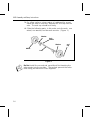
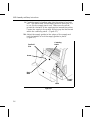
4. Slide the following parts, in this order, onto the axle: one
wheel, one washer, and two axle mounts. (Figure 1.)
nDo Not install the second end cap without first inserting the
axle mounts into the sockets. The sockets prevent the axles
from being positioned too close together.
Figure 1
Axle
Mount
Axle
Wheel
end
cap
Washer
Washer
9476 Assembly and Setup Instructions
1-4

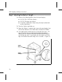
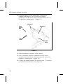
5. At the rear of the Station (end closest to the side where
the cabinet door opens), push the two axle mounts firmly
into the sockets of the rear legs. (Figure 2.) Hold onto
the uncapped end of the axle so the axle assembly stays
together.
6. Place the other end cap onto the uncapped end of the
axle. Press the cap firmly (with your thumb) to temporarily
hold the cap in place.
7. Hold the axle firmly with one hand, while tapping the end
cap onto the axle with a rubber mallet. Make sure the end
cap fits firmly onto the axle.
8. Push the two casters into the sockets in the bottom of the
front legs. (Figure 2.)
9. Tap the axle mounts and casters with a rubber mallet to
fully seat them.
Figure 2
Axle
Mount
Socket
Caster
Chapter 1. Assembling the Station
1-5

Step 2: Adjusting the Station’s Height--------------------------------------------------
1. Remove the following items from their packaging:
F (4) 1/4"-20 x 3/4" bolts (black)
F (4) 1/4"-20 wing nuts (black)
F (1) plastic cable-tube clamp (may already be attached
to the cable tube)
2. Turn the Station right side up.
3. Open the Station’s cabinet and remove the packaging from
around the bottom of the cable tube and from the cables.
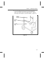
4. You might need another person’s help with this step. Lift
the top shelf to the second-highest height adjustment.
Make sure the cables inside the cable tube feed freely as
you lift the top shelf. Insert bolts into the holes in all four
legs and fasten them with wing nuts as shown. (Figure 3.)
Figure 3
Cable
Clamp
Cable
Tube
9476 Assembly and Setup Instructions
1-6

nDo Not set the top shelf to the highest adjustment.
5. Attach the plastic cable-tube clamp around the bottom of
the cable tube as shown (if it is not already attached).
Squeeze the finger grips to lock the clamp around the
cable tube. Use pliers to secure the cable clamp tightly.
(Figure 3.)
Step 3: Attaching the Cabinet Handle and Cord Bracket ------------------
Follow the steps below to install the cabinet handle and cord
bracket.
1. Remove the following items from their packaging:
F chrome handle insert
F two 5/8" phillips screws (black)
F cord bracket
F two 8-32 x 1/2" slotted screws (black)
F two 8-32 nuts/lockwashers (black)
Chapter 1. Assembling the Station
1-7

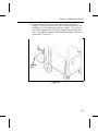
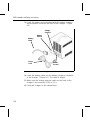
2. Open the Station’s cabinet. Press the chrome handle
insert into the cabinet door and fasten it with two 5/8"
phillips screws. (Figure 4.)
3. Position the cord bracket over the mounting holes on the
lower shelf’s edge shown. Fasten the bracket with two
1/2" slotted screws and 8-32 nuts/lockwashers. (Figure 4.)
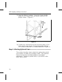
Step 4: Attaching Optional Items----------------------------------------------------------
This section describes how to attach the optional drop shelf,
push handle, and data entry terminal cradle. Each optional
item and necessary mounting hardware is packaged
individually. These are optional items; if you did not order
them, skip to step 5.
Figure 4
Cord
Bracket
Handle
Insert
9476 Assembly and Setup Instructions
1-8

Attach the Push Handle
1. Remove the following items from their packaging:
F (1) push handle
F (4) 1/4"-20 x 3/4" hex bolts
F (4) 1/4"-20 nuts
F (4) 1/4"-20 washers
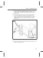
2. Attach the push handle to the front or rear of the Station
using four 3/4" hex bolts, 1/4"-20 washers, and 1/4"-20
nuts as shown. (Figure 5.)
Figure 5
Push
Handle
Chapter 1. Assembling the Station
1-9

Attach the Drop Shelf
1. Remove the following items from their packaging:
F (1) support brace
F (1) metal rod
F (1) drop shelf
F (2) end caps
F (2) 1/4"-20 x 1/2" phillips screws
F (2) plastic washers
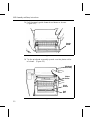
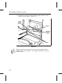
2. Attach the support brace to the Station’s corner supports
on either the front or the rear of the Station using two 1/2"
phillips screws. The open side of the support brace must
face down. (Figure 6.)
nDo not tighten the screws completely.
Figure 6
Corner
Support
Support
Brace
9476 Assembly and Setup Instructions
1-10

3. Slide the metal rod into the hole in the Station’s corner
support and through the support brace until the rod exits
through the hole in the other corner support. You may
have to reach under the support brace to guide the rod
into the opposite hole.
4. Finish tightening the screws to secure the support brace.
5. Remove the metal rod.
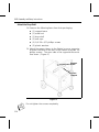
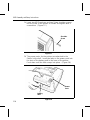
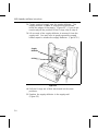
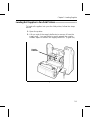
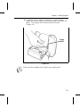
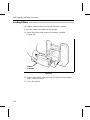
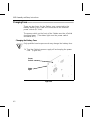
6. Position the rear lip of the drop shelf over the support
brace so the shelf rests in the extended position.
(Figure 7.)
w
To avoid hitting your fingers, use needle-nose pliers to hold
the end cap as you are hammering it.
7. On a firm surface, using a piece of cardboard for a pad,
stand the metal rod on one end. Hammer an end cap onto
the metal rod. The end cap should lock firmly.
8. Slide a plastic washer onto the metal rod.
Figure 7
Metal
Rod
end cap
Drop
Shelf
Support
Brace
Chapter 1. Assembling the Station
1-11

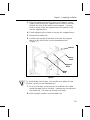
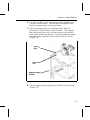
9. Slide the metal rod through the slot in the side of the drop
shelf and into the hole in the Station’s corner support.
Push the rod until it exits through the hole in the other
corner support. You may have to reach under the support
brace to guide the rod into the opposite hole. (Figure 7.)
10. Slide a plastic washer onto the exposed end of the metal
rod. (Figure 7.)
11. You might need another person’s help with this step. Hold
the head or side of a hammer firmly against the end of the
rod with the end cap. While maintaining pressure, use a
second hammer to hammer an end cap onto the exposed
end of the rod. The end cap should lock firmly. (Figure 7.)
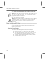
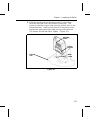
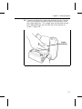
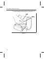
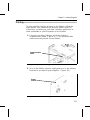
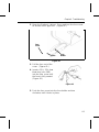
12. To collapse the shelf, lift the shelf from the sides and allow
it to swing down. (Figure 8.)
To extend the shelf, lift the shelf until the rear lip slides
down onto the top of the support brace and locks in place.
Figure 8
9476 Assembly and Setup Instructions
1-12

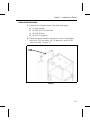
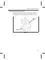
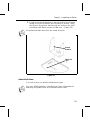
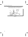
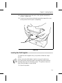
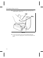
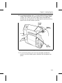
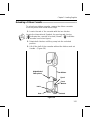
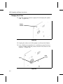
Attach the Data Entry Terminal Cradle
The data entry terminal cradle is shipped fully assembled. To
attach it, place it as shown on any of the Station’s shelves.
The magnets on the cradle anchor it to the Station. (Figure 9.)
Figure 9
Terminal
Cradle
Magnet
Chapter 1. Assembling the Station
1-13

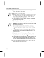
Step 5: Installing the Battery and Charger ------------------------------------------
Follow the steps below to install the battery and battery
charger.
Install the Battery
w
Only qualified service personnel may install or replace the
battery.
1. Remove the following items from their packaging:
F (1) 12-volt battery
F (2) metal retainer rods
F (2) 1/4"-20 wing nuts
F (1) rubber bracket
F (1) green wire
F (1) M5 x 10mm phillips screw
F (2) M5 x 15mm phillips/hex bolts
F (3) M5 nuts
F (2) 1/4"-20 washers
F (2) 1/4"-20 lockwashers
F (2) M5 washers
F (3) M5 lockwashers
9476 Assembly and Setup Instructions
1-14
Page is loading ...
Page is loading ...
Page is loading ...
Page is loading ...
Page is loading ...
Page is loading ...
Page is loading ...
Page is loading ...
Page is loading ...
Page is loading ...
Page is loading ...
Page is loading ...
Page is loading ...
Page is loading ...
Page is loading ...
Page is loading ...
Page is loading ...
Page is loading ...
Page is loading ...
Page is loading ...
Page is loading ...
Page is loading ...
Page is loading ...
Page is loading ...
Page is loading ...
Page is loading ...
Page is loading ...
Page is loading ...
Page is loading ...
Page is loading ...
Page is loading ...
Page is loading ...
Page is loading ...
Page is loading ...
Page is loading ...
Page is loading ...
Page is loading ...
Page is loading ...
Page is loading ...
Page is loading ...
Page is loading ...
Page is loading ...
Page is loading ...
Page is loading ...
-
 1
1
-
 2
2
-
 3
3
-
 4
4
-
 5
5
-
 6
6
-
 7
7
-
 8
8
-
 9
9
-
 10
10
-
 11
11
-
 12
12
-
 13
13
-
 14
14
-
 15
15
-
 16
16
-
 17
17
-
 18
18
-
 19
19
-
 20
20
-
 21
21
-
 22
22
-
 23
23
-
 24
24
-
 25
25
-
 26
26
-
 27
27
-
 28
28
-
 29
29
-
 30
30
-
 31
31
-
 32
32
-
 33
33
-
 34
34
-
 35
35
-
 36
36
-
 37
37
-
 38
38
-
 39
39
-
 40
40
-
 41
41
-
 42
42
-
 43
43
-
 44
44
-
 45
45
-
 46
46
-
 47
47
-
 48
48
-
 49
49
-
 50
50
-
 51
51
-
 52
52
-
 53
53
-
 54
54
-
 55
55
-
 56
56
-
 57
57
-
 58
58
-
 59
59
-
 60
60
-
 61
61
-
 62
62
-
 63
63
-
 64
64


Paxar Mobile Printing Station Monarch 9476 User manual
- Category
- Label printers
- Type
- User manual
- This manual is also suitable for
Ask a question and I''ll find the answer in the document
Finding information in a document is now easier with AI
Related papers
-
Paxar Monarch Pathfinder Ultra Gold 6037 User manual
-
-
Paxar Monarch 9416 XL User manual
-
-
-
Monarch 9414 User manual
-
-
-
-
Other documents
-
Havis-Shields PRM97422 Installation guide
-
Black Max BM80544 Owner's manual
-
DeLOCK 46276 Datasheet
-
-
 Star Trading CRYSTAL PAPIRSTJERNE GRØNN Quick start guide
-
 Star Trading CRYSTAL PAPIRSTJERNE ROSA Quick start guide
-
GE JDP40WBWW Installation guide
-
 Rolling Shelves RSXP23 Installation guide
-
Avery Dennison 9493SNP Quick Reference Manual
-
Avery Dennison 9433 Operating instructions


