Page is loading ...

Hoshizaki
“A Superior Degree
of Reliability”
www.hoshizaki.com
Model
DKM-500BAH
Crescent Cube Icemaker / Dispenser
Hoshizaki America, Inc.
Service Manual
™
Number: 73138
Issued: 9-20-200
6

2
IMPORTANT
Only qualified service technicians should attempt to service or maintain this
unit. No such service or maintenance should be undertaken until the technician
has thoroughly read this Service Manual.
HOSHIZAKI provides this manual primarily to assist qualified service technicians in the
service and maintenance of the unit.
Should the reader have any questions or concerns which have not been satisfactorily
addressed, please call, write or send an e-mail message to the HOSHIZAKI Technical
Support Department for assistance.
HOSHIZAKI AMERICA, INC.
618 Highway 74 South
Peachtree City, GA 30269
Attn: HOSHIZAKI Technical Support Department
Phone: 1-800-233-1940 Technical Service
(770) 487-2331
Fax: 1-800-843-1056
(770) 487-3360
E-mail: techsuppor[email protected]
Web Site: www.hoshizaki.com
NOTE: To expedite assistance, all correspondence/communication MUST include the
following information:
• Model Number
• Serial Number
• Complete and detailed explanation of the problem

3
Please review this manual. It should be read carefully before the unit is serviced or
maintenance operations are performed. Only qualified service technicians should service
and maintain the unit. This manual should be made available to the technician prior to
service or maintenance.
CONTENTS
I. Specifications ...................................................................................................................... 5
II. General Information ........................................................................................................... 6
A. Construction .................................................................................................................. 6
B. Sequence of Operation ................................................................................................. 7
1. One Minute Fill Cycle .............................................................................................. 7
2. Initial Harvest Cycle ................................................................................................ 7
3. Freeze Cycle ........................................................................................................... 7
4. Pump-Out Cycle ..................................................................................................... 7
5. Normal Harvest Cycle ............................................................................................ 7
C. Control Board ................................................................................................................ 9
1. Control Board Layout ............................................................................................. 10
2. Features ................................................................................................................ 11
a) Maximum Water Supply Period – 6 minutes ...................................................... 11
b) Harvest Backup Timer and Freeze Timer .......................................................... 11
c) High Temperature Safety ................................................................................... 11
d) Low Water Safety .............................................................................................. 11
e) High Voltage and Low Voltage Cut-outs ............................................................ 11
f) LED Lights and Audible Alarm Safeties .............................................................. 12
3. Controls and Adjustments ..................................................................................... 13
a) Default Dip Switch Settings ............................................................................... 13
b) Harvest Control – Thermistor ............................................................................ 13
c) Harvest Timer (dip switch 1 & 2) ........................................................................ 14
d) Pump-Out Timer (dip switch 3 & 4) ................................................................... 14
e) Pump-Out Frequency Control (dip switch 5 & 6) ............................................... 15
f) Freeze Timer (dip switch 9 & 10) ........................................................................ 15
g) Bin Control ........................................................................................................ 15
4. Bin Control Troubleshooting ................................................................................... 16
a) Machine Will Not Start ....................................................................................... 16
b) Machine Will Not Shut Off ................................................................................. 16
5. Control Board Check Procedure ............................................................................ 16
6. Control Board Replacement .................................................................................. 17
D. Switches ...................................................................................................................... 17
1. Control Switch ....................................................................................................... 17
2. Service Switch ....................................................................................................... 17
a) DRAIN ............................................................................................................... 17
b) CIRCULATE ...................................................................................................... 18
c) WASH ................................................................................................................ 18

4
III. Technical Information ...................................................................................................... 19
A. Water Circuit and Refrigeration Circuit ........................................................................ 19
B. Wiring Diagram ............................................................................................................ 20
C. Timing Chart ............................................................................................................... 21
D. Performance Data ....................................................................................................... 23
IV. Service Diagnosis ........................................................................................................... 24
A. 10-Minute Diagnostic Procedure ................................................................................ 24
B. Diagnostic Charts ........................................................................................................ 25
1. Ice Making ............................................................................................................. 25
a) No Ice Production .............................................................................................. 25
b) Evaporator is Frozen Up .................................................................................... 28
c) Low Ice Production ............................................................................................ 29
d) Abnormal Ice ..................................................................................................... 29
e) Other ................................................................................................................. 30
2. Dispensing ............................................................................................................. 30
V. Removal and Replacement of Components .................................................................... 32
A. Service for Refrigerant Lines ...................................................................................... 32
1. Refrigerant Recovery ............................................................................................. 32
2. Evacuation and Recharge (R-404A) ...................................................................... 32
B. Brazing ........................................................................................................................ 33
C. Removal and Replacement of Compressor ................................................................ 33
D. Removal and Replacement of Drier ............................................................................ 34
E. Removal and Replacement of Expansion Valve .......................................................... 35
F. Removal and Replacement of Hot Gas Valve .............................................................. 35
G. Removal and Replacement of Evaporator .................................................................. 36
H. Removal and Replacement of Condenser .................................................................. 37
I. Removal and Replacement of Thermistor .................................................................... 38
J. Removal and Replacement of Fan Motor .................................................................... 38
K. Removal and Replacement of Inlet Water Valve ......................................................... 39
L. Removal and Replacement of Pump Motor ................................................................. 39
M. Removal and Replacement of Spray Tubes ................................................................ 40
N. Removal and Replacement of Gear Motor ................................................................ 40
O. Removal and Replacement of Dispense Switch ......................................................... 41
P. Removal and Replacement of Solenoid ...................................................................... 41
VI. Cleaning and Maintenance Instructions ......................................................................... 42
A. Cleaning Instructions .................................................................................................. 42
1. Cleaning Procedure – Icemaker ............................................................................ 42
2. Sanitizing Procedure – Icemaker ........................................................................... 43
3. Cleaning Procedure – Bin ...................................................................................... 44
4. Sanitizing Procedure – Bin .................................................................................... 44
B. Maintenance Instructions ............................................................................................ 45
1. Exterior Panels ...................................................................................................... 45
2. Air Filters ............................................................................................................... 45
3. Condenser ............................................................................................................. 45
C. Preparing the Icemaker for Long Storage ................................................................... 45

5
AC SUPPLY VOLTAGE 115/60/1
AMPERAGE 13.3 A ( 5 Min. Freeze AT 104°F / WT 80°F)
MINIMUM CIRCUIT AMPACITY 15 A
MAXIMUM FUSE SIZE 15 A
APPROXIMATE ICE PRODUCTION Ambient WATER TEMP. (°F)
PER 24 HR. Temp.(°F) 50 70 90
lbs./day ( kg/day ) 70 *466 (211) 448 (203) 420 (191)
Reference without *marks 80 453 (205) 425 (193) 395 (179)
90 448 (203) *406 (184) 376 (170)
100 390 (177) 399 (181) *348 (158)
SHAPE OF ICE Crescent Cube
ICE PRODUCTION PER CYCLE 7.2 lbs. (3.2 kg) 360 pcs.
APPROXIMATE STORAGE CAPACITY 200 lbs (91 Kg)
APPROXIMATE ICE DISPENSING SPEED 13 lbs/min (6 kg/min)
ELECTRIC & WATER CONSUMPTION 90/70°F 70/50°F
ELECTRIC W (kWH/100 lbs.) 1150 (6.8) 1049 (5.4)
WATER gal./24HR (gal./100 lbs.) 66 (16.3) 110 (23.6)
EXTERIOR DIMENSIONS (WxDxH) 30" x 28" x 77" With 6" Flanged Legs
EXTERIOR FINISH Stainless Steel, Galvanized Steel (Rear)
INTERIOR FINISH Polyethylene 1 pc. Mol
d
INSULATION Polyurethane Foam
WEIGHT Net 385 lbs. ( 175 kg ), Shipping 410 lbs. (186 kg)
CONNECTIONS - ELECTRIC Cord Connection
- WATER SUPPLY Inlet 1/2" FPT
- DRAIN Outlet 3/4" FPT x 2
CUBE CONTROL SYSTEM Float Switch
HARVESTING CONTROL SYSTEM Hot Gas and Water, Thermistor and Timer
ICE MAKING WATER CONTROL Timer Controlled. Overflow
COOLING WATER CONTROL N/A
BIN CONTROL SYSTEM Proximity Switch with Delay
COMPRESSOR Hermetic, Model RS55C2E-CAA-219
CONDENSER Air-cooled, Fin and tube type
EVAPORATOR Vertical type, Stainless Steel and Copper
REFRIGERANT CONTROL Thermostatic Expansion Valve
REFRIGERANT CHARGE R-404A, 2lbs (907g)
DESIGN PRESSURE High 467 PSIG, Low 170 PSIG
P.C. BOARD CIRCUIT PROTECTION High Voltage Cut-out ( Internal )
COMPRESSOR PROTECTION Auto-reset Overload Protector ( Internal )
REFRIGERANT CIRCUIT PROTECTION Auto-reset High Pressure Control Switch
LOW WATER PROTECTION Float Switch
ACCESSORIES -SUPPLIED N/A
OPERATING CONDITIONS VOLTAGE RANGE 104 - 127 V
AMBIENT TEMP. 45 -100° F
WATER SUPPLY TEMP. 45 - 90° F
WATER SUPPLY PRESSURE 10 - 113 PSIG
I. Specifications
A. DKM-500BAH
Note: We reserve the right to make changes in specifications and design without prior
notice.

6
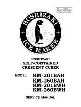
II. General Information
A. Construction
1. DKM-500BAH
Spray Tubes
Water Supply
Inlet
Condenser
Condenser
Fan Motor
Control Box
Drier
Hot Gas Valve
Compressor
Float Switch
Water Pump
Mechanical Bin
Control
Control
Switches
Expansion
Valve
Agitator
Bin
Gear Motor
Assembly
Solenoid
Assembly
Drain Pan
Front Panel
Shutter
Dispense Switch
Spout
Extension
Bin Cover
Inlet Water Valve
Circulating Valve
Drain Valve
Chain
Ice Cube Guide
Strainer
Dispense Switch
Connector

7
B. Sequence of Operation
The steps in the sequence are as outlined below. When power is supplied, a 5 second
delay occurs at startup. Note that the order of the LEDs from the outer edge of the board
is 1, 4, 3, 2.
1. One Minute Fill Cycle
LED 4 is on. WV opens and the fill period begins. After 1 minute, the board checks for a
closed F/S. If F/S is closed, the harvest cycle begins. If not, the unit will not start without
adequate water in the sump. This serves as a low water safety to protect the water pump.
WV will remain energized through additional 1 minute cycles until water enters the sump
and F/S closes.
2. Initial Harvest Cycle
LEDs 1, 4, and 2 are on. WV remains open, Comp energizes, HGV opens, and harvest
begins. As the evaporator warms, the thermistor located on the suction line checks for a
48°F (9°C) temperature. When 48°F (9°C) is reached, a 3.9 kΩ signal turns the harvest
over to the adjustable harvest timer which is factory set for normal conditions. The timer
has settings of 60, 90, 120, and 180 seconds (dip switch 1 & 2). When the harvest timer
completes its count down, the harvest cycle is complete and the freeze cycle starts. The
minimum total time allowed by the board for a complete harvest cycle is 2 minutes.
3. Freeze Cycle
LED 1 is on. Comp continues to run, PM and FMS energize, HGV and WV close and
the freeze cycle starts. For the first 5 minutes the control board will not accept a signal
from F/S. This 5 minute minimum freeze acts as a short cycle protection. At the end of
5 minutes, F/S assumes control. As ice builds on the evaporator the water level in the
sump lowers. The freeze continues until F/S opens and terminates ice production.
4. Pump-Out Cycle
LEDs 1, 3, and 2 are on. Comp continues to run, HGV opens, and FMS de-energizes.
PM stops for 2 seconds. SR energizes, restarting PM and taking water from the sump
and forcing it to go through DV and down the drain. When the pump-out timer stops
counting, the pump out is complete.
Pump out always occurs on the 2nd harvest after startup. Then, depending on the control
board setting, pump out occurs every cycle, or every 2nd, 5th or 10th cycle (dip switch
5 & 6).
5. Normal Harvest Cycle
LEDs 1, 4, and 2 are on. Comp continues to run, HGV remains open and WV opens.
As the evaporator warms, the thermistor reaches 48°F (9°C). The control board then
receives the thermistor's 3.9 kΩ signal and starts the harvest timer. The water valve is
open during harvest for a maximum of 6 minutes or the length of harvest, whichever is
shorter. When the harvest timer completes its count down, the harvest cycle is complete
and the next freeze cycle starts.
Note: The unit continues to cycle through 3, 4 and 5 sequence until the bin control is
activated (within first 5 minutes of freeze) and shuts the unit down.
Legend:
Comp–compressor; DV–Drain Valve; FMS–self-contained fan motor; F/S–float
switch; HGV–hot gas valve; PM–pump motor; SR–Service Relay; WV–inlet water
valve

8
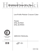
DKM-500BAH Sequence Flow Chart and Component Operation
1. One Minute
Fill Cycle
4. Pump-Out
Cycle
Cycle Steps
WV Energized
F/S open
F/S closed
Comp energized
HGV energized
WV continues
Thermistor temp
reaches 48°F (9°C)
(3.9 kΩ or less)
Harvest timer starts
F/S open
Comp continues
HGV de-energized
WV de-energized
PM energized
FMS energized
F/S closed
Freeze cycle
operation turned
over to
F/S
PM stops for 2 sec., SR
energizes, starting PM &
DV for 10/20 sec. each 1,
2, 5, or 10 cycles.
Comp continues
HGV energized
FMS de-energized
F/S Check
F/S Check
2. Harvest Cycle
• Maximum inlet water valve time: 6 minutes
• Maximum harvest time: 20 minutes
Thermistor in
control
1 to 3 minute timer
in control
3. Freeze Cycle
• Minimum freeze time: 5 minutes
• Maximum freeze time: freeze timer setting
• Bin control can only shut down unit within
first 5 minutes of freeze cycle
5 minute timer
in control
F/S in
control
Initial startup always
begins here
"E" board will have
5 second delay
If F/S is open, compressor stops and cycle returns to 1 minute fill
Legend:
Comp–compressor; DV–drain valve; FMS–self-contained fan motor; F/S–float switch;
HGV–hot gas valve; PM–pump motor; SR–service relay; WV–inlet water valve

9
C. Control Board
• A HOSHIZAKI exclusive solid-state control is employed in the DKM-500BAH Crescent
Cube Icemaker / Dispenser.
• All units are pretested and factory-adjusted.
CAUTION
1. Fragile, handle very carefully.
2. A control board contains integrated circuits, which are susceptible to failure
due to static discharge. It is especially important to touch the metal part of
the unit when handling or replacing the board.
3. Do not touch the electronic devices on the board or the back of the board to
prevent damage to the board.
4. Do not change wiring and connections. Do not misconnect K3, K4 and K5,
because the same connector is used for the thermistor, float switch and
mechanical bin control.
5. Always replace the whole board assembly if it goes bad.
6. Do not short out power supply to test for voltage.

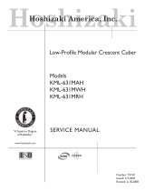
10
Control Board
Part Number 2A1410-01 (factory); 2A1410-02 (service)
Type HOS-001A (Control Products - 10 Pin)
Output Test Switch
(used to test relays on board)
Connector K3
Harvest Control
(thermistor)
Connector K4
Mechanical Bin
Control
Microprocessor
(board revision level
indicated by last 2
digits on label)
Connector K5
Float Switch
Part Number
Connector K1
Pins #1 through #10
#1, 9 Magnetic Contactor
#2 Hot Gas Valve
#3 Self-Contained Fan Motor (FMS)
#4 Pump Motor (icemaking)
#5 Pump Motor (drain)
#6 Water Valve
#7, 10 Power (line, bin control)
#8 Open
Switch for "C" board
and "ALPINE" board
(service boards only)
Alarm Reset Switch
Backup Freeze
Timer LED
Dip Switch
Backup Harvest
Timer LED
Alarm Buzzer
Power LED
(lights when
power is supplied
to the board)
Relay LEDs (4)
(indicate which
relays are energized
as listed below)
LED 2
Hot Gas Valve (HGV)
Self-Contained Fan
Motor (FMS) (FMS
off when LED on)
LED 3
Pump Motor (PM)
(on at pump out only)
LED 4
Water Valve (WV)
LED 1
Compressor (Comp)
Transformer
Connector
Control Products "E" Control Board
1. Control Board Layout

11
2. Features
a) Maximum Water Supply Period – 6 minutes
Inlet water valve opening, in the harvest cycle, is limited by the harvest timer. The water
valve cannot remain open longer than the maximum period. The water valve can close in
less than six minutes if the harvest cycle is completed.
b) Harvest Backup Timer and Freeze Timer
The harvest backup timer shuts down the icemaker if, for two cycles in a row, the harvest
cycle takes more than 20 minutes to complete. The control board will signal this problem
using 2 beeps every 3 seconds.
The freeze timer shuts down the icemaker if, for two cycles in a row, the freeze cycle
takes longer than the time specified to complete. The control board will signal this
problem using 3 beeps every 3 seconds. The time is factory set using dip switches 9 &
10.
The reset button on the control board must be pressed with power on to reset either of
these safeties.
c) High Temperature Safety
The temperature of the suction line in the refrigeration circuit is limited by the high
temperature safety. This protects the unit from excessively high temperatures. If the
evaporator temperature rises above 127 ± 7°F (53 ± 4°C), the thermistor operates the
safety. This shuts down the circuit and the icemaker automatically stops.
The control board will signal this problem using 1 beep every 3 seconds. The reset button
on the control board must be pressed with power on to reset the safety.
d) Low Water Safety
The control board checks the position of the float switch at the end of the initial one
minute water fill cycle and at the end of each harvest cycle.
If the float switch is in the up position (electrical circuit closed), the control board changes
to the ice making cycle. If the float switch is in the down position (electrical circuit open),
the control board changes to additional one minute water fill cycles until water enters
the sump and the float switch closes. When the float switch closes, the control board
changes to the ice making cycle. The unit will not start without adequate water in the
sump. This serves as a low water safety to protect the water pump.
e) High Voltage and Low Voltage Cut-outs
The maximum and minimum allowable supply voltages of this icemaker are limited by the
high voltage and low voltage cut-outs.
If miswiring (especially on single phase 3 wire models) causes excessive voltage
(147Vac ±5% or more) on the control board, the high voltage cut-out shuts down the
circuit in 3 seconds and the icemaker automatically stops. The control board will signal
this problem using 7 beeps every 3 seconds.
The icemaker also automatically stops in cases of insufficient voltage (92Vac ±5% or
less). The control board will signal this problem using 6 beeps every 3 seconds.
When the proper supply voltage is resumed, the icemaker automatically starts running
again.

12
f) LED Lights and Audible Alarm Safeties
The red LED indicates proper control voltage and will remain on unless a control voltage
problem occurs. At startup a 5 second delay occurs while the board conducts an internal
timer check. A short beep occurs when the power switch is turned OFF.
The green LEDs 1 through 4 energize and sequence from initial startup as listed in the
table below. Note that the order of the LEDs from the outer edge of the board is 1, 4, 3, 2.
For more information, see "II.B. Sequence of Operation."
Sequence Step LED
Energized
Components
Time LEDs are On
Min. Max. Avg.
1 Minute Fill Cycle
4 WV 60 seconds
Harvest Cycle
1, 4, and 2 WV, HGV,
Comp
2 minutes 20 minutes 3 to 5 minutes
Freeze Cycle
1 Comp, PM,
FMS
5 minutes freeze timer
setting
30 to 35 minutes
Pump Out 1, 3, and 2 Comp, HGV,
PM, SR, DV
10 seconds 20 seconds factory setting
The built in safeties shut down the unit and have alarms as follows:
No. of Beeps
(every 3 sec.)
Type of Alarm
Notes
1 High Evaporator Temp.
(temperature > 127°F)
(53°C)
Check for harvest problem (stuck HGV or
relay), hot water entering unit, or shorted
thermistor.
2 Harvest Backup Timer
(harvest > 20 min. for two
cycles in a row)
Orange LED marked H TIMER lights up.
Check for open thermistor, HGV not
opening, TXV leaking by, low charge, or
inefficient compressor.
3 Freeze Timer
(freeze > specified setting
for two cycles in a row)
Timer is factory set using
dip switches 9 & 10
Yellow LED marked F TIMER lights up.
Check for F/S stuck closed (up), WV
leaking by, HGV leaking by, TXV not
feeding properly, low charge, or inefficient
compressor.
4 Short Circuit
(between the K4 connec-
tion on the control board
and the bin control)
Resistor wire harness shorted. Check
and replace wire harness if necessary.
5 Open Circuit
(between the K4 connec-
tion on the control board
and the bin control)
Resistor wire harness circuit open or
control board open. Check and replace
component if necessary.
To manually reset the above safeties, press the alarm reset button with the power
supply on.

13
No. of Beeps
(every 3 sec.)
Type of Alarm
Notes
6 Low Voltage
(92Vac ±5% or less)
Red LED will turn off if voltage protection
operates.
The control voltage safeties automatically
reset when voltage is corrected.
7 High Voltage
(147Vac ±5% or more)
Legend:
Comp–compressor; DV–Drain Valve; FMS–self-contained fan motor; F/S–float
switch; HGV–hot gas valve; PM–pump motor; SR–Service Relay; TXV–
thermostatic expansion valve; WV–inlet water valve
3. Controls and Adjustments
a) Default Dip Switch Settings
The dip switch is factory-adjusted to the following positions:
Dip Switch No. 1 2 3 4 5 6 7 8 9 10
DKM-500BAH ON OFF OFF OFF ON ON ON OFF OFF ON
b) Harvest Control – Thermistor
A thermistor (semiconductor) is used for a harvest control sensor. The resistance varies
depending on the suction line temperatures. The thermistor detects the temperature of
the evaporator outlet to start the harvest timer. No adjustment is required. If necessary,
check for resistance between thermistor leads, and visually check the thermistor
mounting, located on the suction line next to the evaporator outlet.
Temperature (°F) Temperature (°C) Resistance (kΩ)
0 -18 14.401
10 -12 10.613
32 0 6.000
50 10 3.871
70 21 2.474
90 32 1.633
Freeze Timer (9 & 10)
Pump-Out Frequency Control (5 & 6)
Pump-Out Timer (3 & 4)
Harvest Timer (1 & 2)
Normally in the OFF position.
Mechanical Bin Control

14
Check a thermistor for resistance by using the following procedure:
1) Disconnect the connector K3 on the board.
2) Remove the thermistor. See "V.H. Removal and Replacement of Thermistor."
3) Immerse the thermistor sensor portion in a glass containing ice and water for 2 or 3
minutes.
4) Verify the temperature of the glass, then check for resistance between thermistor leads.
See the table above for temperature and resistance values. Normal reading is within
3.5 to 7 kΩ. Replace the thermistor if it exceeds the normal reading.
c) Harvest Timer (dip switch 1 & 2)
The harvest timer starts counting when the thermistor reads 48°F (9°C) at the
evaporator outlet.
No adjustment is required under normal use, as the harvest timer is adjusted to the
suitable position. However, a setting longer than the factory setting may be advised in
cases where the flush provided at harvest needs to be prolonged for extra cleaning.
Before changing this setting, call the HOSHIZAKI Technical Support Department at
1-800-233-1940 for recommendations. Keep in mind that setting the harvest timer to a
longer setting will decrease 24 hour production.
Dip Switch Setting Time
(seconds)
No. 1 No. 2
OFF OFF 60
ON OFF 90
OFF ON 120
ON ON 180
d) Pump-Out Timer (dip switch 3 & 4)
When a freeze cycle is completed, the pump motor stops, and the icemaker resumes
operation in 2 seconds. Then, during cycles when a pump out is called for, the pump
motor drains the water tank for the time determined by the pump-out timer. The pump-
out timer also acts in place of the harvest timer during cycles with a pump out.
The pump-out timer is factory-adjusted, and no adjustment is required.
Dip Switch Setting
Time (seconds)
No. 3 No. 4
T1
T2
OFF OFF 10 150
ON OFF 10 180
OFF ON 10 120
ON ON 20 180
T1: Time to drain the water tank
T2: Harvest timer at pump out
Pump out always occurs on the 2nd harvest after startup. Then, depending on the pump-
out frequency control setting (dip switch 5 & 6), pump out occurs every cycle, or every
2nd, 5th or 10th cycle.

15
e) Pump-Out Frequency Control (dip switch 5 & 6)
The pump motor drains the water tank at the frequency set by the pump-out frequency
control.
The pump-out frequency control is factory-adjusted to drain the water tank every 10
cycles, and no adjustment is required. However, where water quality is bad and the
icemaker needs a pump drain more often, the pump-out frequency can be adjusted as
shown in the table below.
Dip Switch Setting
Frequency
No. 5 No. 6
OFF OFF every cycle
ON OFF every 2 cycles
OFF ON every 5 cycles
ON ON every 10 cycles
f) Freeze Timer (dip switch 9 & 10)
CAUTION
Adjust to proper specification, or the unit may not operate correctly.
The freeze timer setting determines the maximum allowed freeze time to prevent
possible freeze-up issues. Upon termination of freeze timer, machine initiates the harvest
cycle. After 2 consecutive timer terminations, machine will shut down, possibly indicating
a problem.
The freeze timer is factory adjusted and no adjustment is required.
Dip Switch Setting Time
(minutes)
No. 9 No. 10
OFF OFF 60
OFF ON 50
ON OFF 70
ON ON 60
g) Bin Control
CAUTION
Dip Switch No. 7 must be set to the ON position. If No. 7 is set to the OFF
position, the machine will run continuously, causing a freeze-up condition.
This machine uses a lever-actuated proximity switch (mechanical bin control) to control
the ice level in the storage bin. No adjustment is required. The bin control is factory-
adjusted.
(1) Explanation of Operation
A resistor wire harness connects the bin control to the K4 connector on the control
board. When the bin control is calling for ice (proximity switch closed), a 7.9 KΩ reading
is sent to the control board to continue operation. When the bin control is activated in the
bin full position (proximity switch open), a 15.8 KΩ signal is sent to the control board to

16
shut down the unit. However, to prevent incomplete batches of ice from forming on the
evaporator, the control board will only shut down the machine within the first 5 minutes of
the freeze cycle. If ice pushes the lever in after the first five minutes of the freeze cycle,
the control board will allow the machine to complete the freeze cycle and the following
harvest cycle before shutting down the machine.
Dip switch number 7 must be in the ON position for the control board to receive input
from the bin control.
4. Bin Control Troubleshooting
a) Machine Will Not Start
1) Move dip switch no. 7 to the OFF position. If the machine starts up within a few
seconds, the bin control is the likely problem. If the machine does not start up, refer to
section "IV. Service Diagnosis" to verify that non-bin control related issues are resolved.
2) Check to make sure shipping tape has been removed and the wires are connected
properly.
3) Check to make sure no obstruction prevents the lever from moving to the bin empty
position.
4) Check proximity switch continuity to make sure it is not stuck open.
b) Machine Will Not Shut Off
1) Refer to Section "IV. Service Diagnosis" to verify that non-bin control related issues are
resolved.
2) Dip switch no. 7 should be in the ON position. If the switch is in the OFF position, the
control board will not receive input from the bin control.
3) Check to make sure no obstruction prevents the lever from moving to the bin full
position.
4) Push the lever in within the first 5 minutes of the freeze cycle. If the machine does not
shut off, check the resistance values of the resistor wire harness. You should read
approximately 15.8 K
Ω between the black terminal and the red terminal that connect to
the K4 connector on the control board when the lever is in the bin full position (proximity
switch open). If this reads approximately 7.9 KΩ, the resistors may be miswired or the
proximity switch may be stuck closed. Switch the black and white wires in the terminal
housing or order a replacement wire harness. If this does not resolve the problem,
replace the bin control assembly.
5. Control Board Check Procedure
Before replacing a control board that does not show a visible defect and that you suspect
is bad, always conduct the following check procedure. This procedure will help you verify
your diagnosis.
1) Check the dip switch settings to assure that #3, 4, 7, 8, 9, & 10 are in the factory default
position. Output test switch S3 should be OFF. Switches 1, 2, 5, & 6 are cleaning
adjustments and the settings are flexible.
2) Turn the control switch to ICE and check for proper control voltage. If the red LED is ON,
the control voltage is good. If the red LED is OFF, check the control transformer circuit.

17
3) Check the 115 volt input at the 10-pin connector. Check the brown wire at pin #10 to a
white neutral wire for 115 volts. (Always choose a white neutral wire to establish a good
neutral connection when checking voltages.) A jumper also feeds 115 volts into pin #7.
If no voltage is present, check the 115 volt supply circuit.
4) The output test switch S3 provides a relay sequence test. With the control switch in the
OFF position, place S3 ON and then move the control switch to the ICE position. The
correct lighting sequence should be none, 2, 3, 4, 1, and 4, normal sequence every 5
seconds. Components (e.g., the compressor) will cycle during the test. Note that the
order of the relays from the outer edge of the board is 1, 4, 3, 2.
Note: If the LEDs light in a different sequence or the 5–second interval does not occur,
the control board is bad and should be replaced.
5) After checking the sequence, place S3 back in the OFF position. The S3 switch must
remain in the OFF position during normal operation. This completes the output test and
the unit is now in the 1 minute fill cycle.
6. Control Board Replacement
The application switch located between relay X3 & X4 must be set to match the original
board application. Place this switch in the ALP position if there is no white wire supplied
to the K1 connector. If there is a white wire, place the switch in the C position. If this
switch is placed in the wrong position either the compressor contactor will remain
energized with the control switch OFF or the unit will not start.
The dip switches should be adjusted to the factory default settings as outlined in this
manual. 8 must remain in the OFF position.
D. Switches
Two control switches are used to control operation. These switches are referred to as the
"control switch" and the "service switch" and are located on the control box.
1. Control Switch
The control switch has three positions: OFF for power off; ICE for icemaking, and
SERVICE to activate the service switch.
2. Service Switch
When the control switch is in the SERVICE position, the control switch supplies power
to the service switch and the machine is in service mode. The service switch has three
positions: DRAIN, CIRCULATE, and WASH. See the information below for details of each
function.
Note:
1. When the service switch is activated, power is supplied to the water pump in all
three positions.
2. When the control switch is in the OFF position or in the ICE position, the service
switch has no power and can be left in any position.
a) DRAIN
This model utilizes a pump-out drain system. When the service switch is active and
placed in the DRAIN position, power is supplied to the pump, service relay and drain
valve.

18
b) CIRCULATE
When the service switch is active and placed in the CIRCULATE position, power is
supplied to the pump only. This operation can be used to circulate cleaner for extended
periods of time over the outside surface of the evaporator.
c) WASH
This model utilizes a solenoid operated cleaning (bypass) valve. When the service
switch is active and placed in the WASH position, power is supplied to the pump and the
cleaning valve. This cleans both the inside and outside of the evaporator plate assembly.

19
III. Technical Information
A. Water Circuit and Refrigeration Circuit
1. DKM-500BAH

20
B. Wiring Diagram
1. DKM-500BAH
* Pressure Switch
Cut-out 412.5 PSIG
Cut-in 327±21.3 PSIG
*
(Service
Relay)
(12V)
/