Newcon Optik 14-3XT User manual
- Category
- Binoculars
- Type
- User manual

Operation Manual
NVS 14 Series
NIGHT VISION MONOCULAR
NVS 14-3XT, NVS 14-3GCS, NVS 14-3AG, NVS 14-3AGBW
105 Sparks Ave., Toronto, ON, M2H 2S5, Canada

ii
This page was intentionally left blank

iii
IMPORTANT INFORMATION
Read prior to activation.
You have purchased a sophisticated electronic device. To
operate it properly, please read this manual carefully.
Ignoring the operation procedures described in this manual
will void your warranty.
NEVER disassemble the Unit. This device contains a source
of high voltage, which may be hazardous to your health.
NEVER open the objective lens of an active Unit in bright
light, including daylight. In the daytime the objective lens
must be covered by the lens cap provided. The tiny hole in
the cap provides enough light for daytime testing.
NEVER aim an active Unit at intense light sources, such as
lights, headlamps, campfires, the moon, etc.
NEVER reverse the polarity of a battery.
NEVER connect the Unit to any external power supplies.
ALWAYS remove battery when not in use for extended
period.
ALWAYS keep the objective lenses covered when not in use.
ALWAYS store the device in a warm dry place.

iv
Precautions
All NVS 14 series devices are sophisticated electro-optical
instruments. They should be handled with due care:
Each Unit contains fragile components. Avoid hard impacts,
dust, moisture and abrupt changes of temperature.
Do not touch the optical surfaces other than for cleaning with
an appropriate lens cleaning kit. Doing so may damage the
anti-reflective coating.
Clean optical surfaces with professional lens cleaning
supplies.
Use only a soft clean cloth to clean the exterior of the device.
Keep the device away from sources of heat, such as heating
appliances, sunlight or central heating.
Switch off the Unit and remove the battery during extended
periods of non-operation.
Do not apply excessive force or pressure to the lens assembly,
movable parts or threaded connections.
Small dark and/or light spots may be seen in the field of view
due to considerable optical magnification of the eyepiece.
This does not affect the operational capabilities of the device.

1
TABLE OF CONTENTS
1.
OVERVIEW .................................................................... 3
2. STANDARD DELIVERY SET ....................................... 5
2.1 Optional accessories .............................................. 5
3. SPECIFICATIONS .......................................................... 6
4. UNIT DESIGN................................................................. 8
5. OPERATION INSTRUCTIONS ..................................... 9
Installing battery............................................................... 9
Activating the Unit ........................................................... 9
Switching the Unit off .................................................... 11
Adjusting to individual vision ........................................ 11
5.1 Manual gain adjustment ...................................... 11
Auto shut OFF at bright light ......................................... 12
Using the Unit with headgear or helmet ......................... 13
Swinging head mounted Unit for unobstructed view ..... 14
Using IR illuminator ...................................................... 14
5.2 Installation of add-on lenses. ............................... 15
Demist shield and sacrificial window ............................ 16
Using the camera / video adapter ................................... 17
Using the helmet mount ................................................. 17
Mounting on a rifle ......................................................... 18
Using with a daytime riflescope ..................................... 19
Binocular configuration ................................................. 19

2
6. TROUBLESHOOTING ................................................. 21
No green (or black and white) image visible .................. 21
Image is unclear ............................................................. 21
Image flashes .................................................................. 21
Condensation accumulates on Unit ................................ 21
Visibility decreased or disappeared ................................ 22
7. WARRANTY ................................................................. 23
8. CUSTOMER SUPPORT ............................................... 24
9. ACCEPTANCE CERTIFICATE ................................... 25

3
1. OVERVIEW
Your NVS 14 series device (the “Unit”) is an optoelectronic
monocular, intended for observation of objects and orientation at
night or under dark conditions. The Unit is equipped with a
Generation 3 (“Gen 3”) image intensifier tube (“IIT”), which
amplifies low light, such as moonlight, starlight or man-made
light. The Unit is waterproof to the depth of 1 meter for 30
minutes (with the exception of NVS 14-3GCS which is
waterproof to 20 meters for 30 minutes).
3x, 4x and 8x add-on lenses can be attached to the Unit to
increase system magnification for use as a longer range
observation sight.
Utilizing the optional mechanical bridge, two Units can be
combined to form night vision binoculars.
In its 1x configuration, the Unit can be mounted on a combat
helmet or head harness.
Some typical activities where NVS 14 series devices can be
useful:
Law enforcement
Wildlife observation
Security
Search and rescue
Hunting (where permitted by law)

4
Features
Flip-up mechanism provides for unobstructed vision when
the Unit is mounted on headgear or helmet;
Built-in infrared illuminator enables observation in total
darkness (i.e. basement, cave or dark room);
Optional NVS H Mount (helmet mount) allows for
effective combat operations;
Optional weapon mount converts Unit to a night vision
weapon sight that can be used alone or in conjunction
with other daytime weapon sights;
Soft rubber eyecup makes viewing comfortable;
Utilizing the NVS Camera/Video Adaptor, the Unit can be
connected to photo or video camera for surveillance
operations.
Please read all the instructions carefully prior to using the Unit.
Manufacturer reserves the right to introduce minor design
changes without notice.
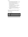
NVS 14 Series Models
Model Brief Description
NVS 14-3XT Military specification night vision monocular with 1x magnification, Gen 3 IIT, helmet/head/weapon
mountable, green image, 1meter waterproof.
NVS 13-3GCS Military specification night vision monocular with 1x magnification, Gen 3 IIT, helmet/head/weapon
mountable, green image, 20 meter waterproof.
NVS 14-3AG Military specification night vision monocular with 1x magnification, Gen 3 IIT, auto-gated power
supply helmet/head/weapon mountable, green image, 1 meter waterproof.
NVS 14-3AGBW Military specification night vision monocular with 1x magnification, Gen 3 IIT, auto-gated power
supply helmet/head/weapon mountable, black and white image, 1 meter waterproof.

5
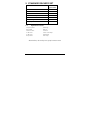
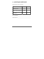
2. STANDARD DELIVERY SET
QUANTITY
NVS 14 Series Unit 1
Head Harness 1
NVS Arm Mount 1
Objective Lens Cap 1
Operation Manual 1
Lens Cleaning Kit 1
AA battery 1
2.1 Optional accessories
US-style clip mount
Demist shield
Sacrificial window
3x add-on lens
5x add-on lens
Weapon mount
NVS Bridge
Hard case
Lens brush
Camera / video adapter
NVS H Mount
NVS Coupler
Exact Delivery Set is subject to specific contract terms.

6
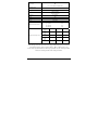
3. SPECIFICATIONS
Model 3XT 3GCS 3AG 3AGBW
IIT Generation Gen 3
Photocathode Material Gallium Arsenide (GaAs)
Image Colour Green
Black &
White
Photocathode Diameter 17.5mm
Minimum Photocathode
Sensitivity
1800 µA/lm
1
190 mA/W
2
Luminous Gain
40,000 – 70,000 fL/fc
3
10,000 – 20,000 fL/fc
4
Auto-gating X
Minimum Resolution
5
64 lp/mm
Minimum Signal to Noise
6
24
Bright Source Protection
Automatic Brightness Control
Auto-gating X
Manual Gain Control
Manual Gain Adjustment
Range
20 – 100%
Magnification 1x
Field of view (1x)
40
Focus range 0.25m to infinity
Exit pupil diameter 20mm
Eye relief 25mm
Dioptric correction
5
1
@2856°K
2
@830nm
3
@2x10⁻⁶ fc
4
@2x10⁻⁴ fc
5
,
6
Higher minimum available as per contract

7
Power supply
1x 3V CR-123 Lithium battery
OR
1x 1.5 V AA Alkaline or lithium battery
Maximum Current
Consumption
25 mA
Voltage
2.8
0.8
Battery life
20 hours with I/R
40 hours without I/R
Dimensions 118x48x69mm
Weight 300g
Operating Temperature Range -50 to +55 °C
MTBF 10,000 hours
Modulation Transfer Function
@2.5 lp/mm 92%
@7.5 lp/mm 80%
@15.0 lp/mm 61%
@25.0 lp/mm 38%
Black Spots Allowed per Zone
Spot Size
(inches)
Zone 1 Zone 2 Zone 3
0.012 ~
0.015
0 0 0
0.009 ~
0.012
0 0 0
0.006 ~
0.009
0 1 1
0.003 ~
0.006
0 2 2
As the design of NVS 14 series devices is being continuously improved, delivered
specifications may be superior to those above. Where a discrepancy exists
between the specifications above and the specifications in your contract/purchase
order, the contract/purchase order takes precedence.

8
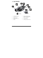
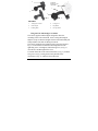
4. UNIT DESIGN
1. On/Off/IR/Auto switch
2. Objective lens cap
3. Objective lens
4. Eyepiece with eyecup
5. Housing
6. Battery compartment cover
and battery selection bushing
7. Battery compartment
8. Dovetail platform
9. Manual gain adjustment knob
FIGURE 1
1
2
7
6
9
4
5
8
3

9
5. OPERATION INSTRUCTIONS
Installing battery
Unit is supplied without a battery installed.
Prior to installing the battery, make sure the On/Off/IR/Auto
switch (1, Fig.1) is in the OFF position and the objective lens
cap is on.
The Unit can operate on either a single AA or CR-123 lithium
battery. Lithium batteries hold a charge longer than conventional
batteries and provide better performance at low temperatures.
To install a battery remove the battery compartment cover (6,
Fig.1) by rotating it counter clockwise. When using a CR-123
lithium battery, remove the battery bushing located under the
battery compartment cover by rotating it counter clockwise.
Store the bushing in a safe place while not in use. Make sure the
battery is installed with the correct polarity as indicated on the
housing. Insert the battery and replace the battery cover.
Activating the Unit
In daylight ensure the objective lens cap is in place prior
to activating the Unit.
To check if the Unit is operational switch it ON by rotating the
On/Off/IR/Auto switch clockwise while looking through the
eyepiece (4, Fig.1). You should see either a green or black and
white image (depending on the model you have purchased). If

10
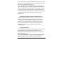
FIGURE 2
IR illuminator indicator (red,
left), Low battery indicator
(yellow, right)
the screen is not lit ensure the batteries installed are charged
and the polarity is correct.
When the Unit is ON you may see a
red and/or yellow LED indicator in
the field of view (Fig. 2). When the
yellow or red LED indicators are
flashing, the remaining battery
power is low and it should be
changed. For uninterrupted operation
keep a fresh battery ready and
replace it on time. If the red LED
indicator is lit solidly, the IR
illuminator is activated. This
warning is intended to prevent the
user from unintentionally giving
away their position.
In the daytime with the objective lens cap on, it is normal to
observe a ‘fuzzy’ image. Switching on the Unit in the daytime is
intended for testing purposes only. During night use, the
objective lens cap should be removed and the ‘fuzzy’ image
should no longer be observed.
The rotating switch has four positions: “Off”, “Auto”, “On”,
“IR”. In Auto mode the monocular will switch off automatically
when turned upright. This mode saves battery life and avoids
unintentionally illuminating the users face during combat
operations.

11
Switching the Unit off
After you have finished using the Unit, turn it off by rotating the
On/Off/IR/Auto switch to the ‘OFF’ position. Replace the
objective lens cap. If storing the unit for an extended period,
remove batteries. Place Unit in appropriate storage container.
Adjusting to individual vision
Turn on the Unit. Direct the Unit at an object placed within 8-15
m from the viewer. While looking through the Unit at the object,
first rotate the diopter adjustment ring on the eyepiece (4, Fig. 1).
Once focus is nearly achieved, rotate the objective lens (3, Fig. 1)
to achieve final focus.
5.1 Manual gain adjustment
Each NVS 14 series device is equipped with a manual gain
adjustment system (9, Fig. 1). This system allows the user to
adjust the gain (or light amplification) of the Unit in accordance
with the prevailing light conditions.
The manual gain system allows for the gain of the Unit to be set
between 20% and 100%. In relatively dark situations, the gain
should be set high enough that the user can see a clear, well-lit
image in the eyepiece. In relatively bright conditions, the gain
should be reduced to avoid an overly brightened image from
being displayed in the eyepiece.

12
Auto shut OFF at bright light
Each unit has a built-in high light sensor located near the IR
illuminator (2, Fig. 1). This sensor shuts the monocular off after
about 45 seconds of exposure to light exceeding 10
-1
lux.
To reset the monocular switch it off and then back on as
described in 6.3 and 6.2.
High-light shut-off feature does not mean that the Unit will react
to occasional flashes or bright spots. It protects the tube against
excessive light exposure only in order to avoid permanent
damage.
Auto-gating system
The NVS 14-3AG and NVS 14-3AGBW variants contain, in
addition to the systems described above, an auto-gated power
supply. This system automatically controls the power supplied to
the IIT in changing lighting conditions. This serves not only to
protect the IIT from exposure to bright lighting sources, but also
to automatically provide the user with the optimal image
regardless of prevailing light condition.

13
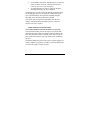
FIGURE 3
1. “Swing arm” mount
2. Grooved pad
3. Locking knob
4. Unit groove
5. Flip button
6. US clip mount
Using the Unit with headgear or helmet
The Unit is supplied with headgear designed to allow the
mounting of the Unit on the head. Prior to using the headgear
adjust its straps so that the headgear fits the head comfortably but
firmly and does not slide off during movement.
The Unit is attached to the headgear with a swing arm mount (1,
Fig. 3). To attach the arm mount to the headgear loosen the
tightening screw on headgear, slide helmet groove (2, Fig. 3)
onto the rail, and then tighten the screw.
To attach monocular to the arm turn the knob (3, Fig. 3), slide the
arm groove (4, Fig.3) along the dovetail platform of the
monocular (8, Fig. 1), and then release the knob.
Technical
drawing of US
cli
p
moun
t
3
1
6
5
2
4

14
To set comfortable eye-relief (the distance between your eye and
the eyepiece), loosen tightening screw on the headgear and move
the Unit, then tighten the locking screw.
To use the Unit with PASGT head and helmet mount unscrew
the grooved pad (2, Fig. 3) from the swing arm mount and screw
on the US type clip (6, Fig. 3) using four screws (Fig. 3) instead.
US type helmet clip is optional and must be ordered seperately.
To switch between left and right eye, press the flip button (5, Fig.
3) on the mount and rotate it respectively until you hear an
audible click.
Swinging head mounted Unit for unobstructed view
When the head mounted Unit is not in use you can raise it to
clear the view without taking the headgear off by using the
“flip/flop” feature. To swing the Unit from the view press the
button (5, Fig. 3) and raise the device until you hear a click.
In “Auto” position of the switch, the monocular will turn off
automatically. Reverse the operation to return the Unit to
working position.
Using IR illuminator
In case of insufficient light when observing a close object turn on
the IR illuminator by turning the On/Off/IR/Auto switch.
Red indicator visible through the eyepiece will warn you when
the IR illuminator is on.
Note: The IR illuminator is visible to anybody equipped with a
night vision device and can disclose the user’s presence.

15
5.2 Installation of add-on lenses.
Always ensure that the Unit is switched off when adding or
removing an objective lens.
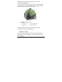
To attach the afocal 3x add-on lens to the Unit, turn off the
monocular. Remove the objective lens cap. Press the 3x lens
firmly towards the eyepiece. Do not apply excessive pressure.
Make sure that the lens is fixed well on the monocular. To return
the monocular back to 1x magnification, pull off the lens.
To attach the 5x or 8x add-on lenses, follow the following
procedure:
1. Make sure the Unit is off.
2. Remove the objective lens cap.
FIGURE 4
NVS 14 with afocal 3x lens

16
3. To detach the current lens: hold the lens by its base and
rotate it counter-clockwise. Once the lens has been
removed, store it in a safe, clean space.
4. To attach desired lens: rotate it clockwise along the
threading until snug—do not overtighten.
The threads are very fine (to prevent humidity penetration) and
can be damaged easily. Do not apply force when rotating the
lens. If the desired lens does not rotate smoothly along the
threading, make sure that the threads are aligned.
The Unit is ready for operation immediately after the lens
change. During operation in brightly lit spaces, ensure the
objective lens cap is in place.
Demist shield and sacrificial window
Note: Demist Shield and Sacrificial Window are optional.
The sacrificial window protects the objective lens from sand,
dust and other objects that can scratch or otherwise damage the
lens. The sacrificial window is affixed on the objective lens in
place of the tinted objective lens cap which comes installed on
the Unit.
The demist shield filter protects the eyepiece against fogging. To
install it fold the eyecup down, in order to access the thread, and
screw the filter gently onto the eyepiece.
Page is loading ...
Page is loading ...
Page is loading ...
Page is loading ...
Page is loading ...
Page is loading ...
Page is loading ...
Page is loading ...
Page is loading ...
Page is loading ...
Page is loading ...
Page is loading ...
-
 1
1
-
 2
2
-
 3
3
-
 4
4
-
 5
5
-
 6
6
-
 7
7
-
 8
8
-
 9
9
-
 10
10
-
 11
11
-
 12
12
-
 13
13
-
 14
14
-
 15
15
-
 16
16
-
 17
17
-
 18
18
-
 19
19
-
 20
20
-
 21
21
-
 22
22
-
 23
23
-
 24
24
-
 25
25
-
 26
26
-
 27
27
-
 28
28
-
 29
29
-
 30
30
-
 31
31
-
 32
32


Newcon Optik 14-3XT User manual
- Category
- Binoculars
- Type
- User manual
Ask a question and I''ll find the answer in the document
Finding information in a document is now easier with AI
Related papers
-
Newcon Optik NV207-G2 Operating instructions
-
-
-
-
-
-
-
-
-

